Category Archives: Fiber Testers & Tools

Fiber Optic Connector Cleaning Solution

Fiber optic cabling is the blood vessel of modern telecommunication industry. With the increasing applying of Gigabit Ethernet and 10 Gigabit Ethernet, fiber optic connector cleaning has become one of the most crucial procedures in these fiber optic communication systems. Clean and reliable optical connectors are the most important in providing a reliable, high performance fiber system. Thus, fiber optic cleaning is your best choice of keeping your fiber connectors clean and reliable.

Why Do We Need Fiber Optic Connector Cleaning?

Dirt, dust and other contaminants are the enemies of high-speed data transmission over optical fiber. Today’s network applications require more data and better quality than ever. Hence, it is necessary that all optical connections should free of contaminants to avoid having application performance issue.

Here are pictures showing three different optical connector contaminations. The first picture shows a fiber optic connector with a dry residue.

Fiber-optic-connector-with-dry-residue
Fiber optic connector with dust is displayed in the second picture.
Fiber optic connector with dust
Fiber optic connector with liquid is shown below
Fiber optic connector with liquid contamination

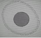
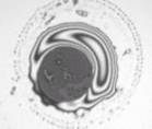
Since fiber optic connector with dust, liquid contamination, dry residue can be easily transferred to the mating ferrule, further complicating the cleaning process. This also runs the risk of physical damage to the fiber’s end face. It is very important to make sure that fiber optic connector is clean.

Fiber Optic Connector Cleaning Methods

Fiber optic cleaning kits on the market can be divided to four types based on the cleaning method.

  • Dry cleaning: Optic cleaning without any use of solvent.
  • Wet cleaning: Optic cleaning with a solvent. Typically IPA (isopropyl alcohol).
  • Non-Abrasive cleaning: Cleaning without abrasive material touching the fiber optic connector end face. Examples are air dusters or pressured solvent jet used in automated in-situ connector cleaners.
  • Abrasive cleaning: The popular lint free wipes, reel based on CLETOP fiber connector cleaners and optic cleaning swabs such as the Cletop sticks are all abrasive cleaning types.
General Cleaning Process
  • Inspect the fiber connector, component, or bulkhead with a fiberscope.
  • Clean it with a dry cleaning method.
  • Inspect the connector again.

Before you select a fiber optic cleaning kit, there are some points you should pay attention to.

  • The connector types will need to be cleaned
  • The type of contaminates will be my technicians encounter
  • The connectors physically located  which place of the network
  • The number of connector ends that need to be cleaned for this project
  • The type of environment  the connectors been exposed to.
  • The skill level of my technicians for cleaning fiber connectors
  • The type of environment my technicians clean in
  • whether the equipment or cable system manufacture have cleaning requirements that must be followed for maintaining the warranty
Fiberstore Fiber Optic Cleaning Solution

Fiberstore’s fiber optic cleaning kits contain the best fiber optic cleaning tools to effectively remove the toughest contaminants in any fiber network. Fiberstore can provide many kinds of fiber cleaners such as fiber connector cleaner, Fujikura cleaner, optical connector cleaning cards, etc. If you have any requirements, please contact us at sales@fs.com or live chat with us.

Introduction of Visual Fault Locator

Many of the problems encountered in troubleshooting fiber optic networks are related to making proper connections. Since the light used in fiber optic systems is infrared (IR) light, which is beyond the range of the human eye and one cannot see it. In order to solve these problems, you need a visual fault locator. Visual fault locator(VFL) is a kind of device which is able to locate the breakpoint, bending or cracking of the fiber glass. It can also locate the fault of OTDR dead–zone and make fiber identification from one end to the other end. This text will give you a brief introduction of visual fault locator.

Working Principle

A powerful visible light from a red diode laser is injected into the fiber, so not only fibers  can be traced, but also high loss points can be made visible. Most applications center on short cables to connect to the fiber optic trunk cables, such as those used in premises cabling or telco central offices. The VFL works best on short cables, up to a few kilometers, thus, it covers the range where optical time-domain reflectometers (OTDRs) are not useful because of the dead zone of the OTDR.

Types of Visual Fault Locator

Visual fault locators generally include the pen type, handheld type and portable visual fiber fault locator.

Pen-style visual fault locator, as showed in the picture below, with a pocket-size, can be carried anywhere easily.

pen type VFL

Hand-held visual fault locator, as the following picture shows, is offered in a range of connector bulkheads styles, from universals to specific connector types.

Handheld VFL

Portable visual fiber fault locator is used to identify fiber and locate faults of single-mode or multi-mode fiber, it is a helpful assistant for finding fault in dead zone of OTDR, it is also a basic maintenance tool for fiber network, LAN, ATM fiber system and telecom network system. The appearance of a portable visual fiber fault locator is showed the following picture.

Portable Visual Fault Locator

Application of Visual Fault Locator

Visual fault locator is a kind of test equipment for testing, troubleshooting and measurement. The VFL is an ideal tool for locating a large number of defects that occur at connection and around fiber cabinets which are hidden in an OTDR “blind-spot” or “dead-zone”. Fiber breaks, faulty connector, sharp bends, bad splices and similar faults can be visually located by light radiated outside the fiber when the light is injected into a fiber. Visual fault locator can boost productivity in the field by providing fast detection, precise fault location, distance, loss, and ORL measurements.

Importance of Visual Fault Locator

The complex network integrated by optical fiber, connector and jumper makes you difficult to find the fault location. So the visual fault locator is an essential tool that quickly and easily locates problem areas in fiber cables. By pinpointing the exact location of fiber damage, technicians can diagnose, troubleshoot and fix the problem timely and efficiently. The VFL is also used for conducting continuous tests and performing fiber identification. With visual fault locator, you can easily isolate high losses and faults in optical fiber cables.

Fiberstore Solution

In terms of its types, applications, importance we can know the VFL is an ideal tool for locating a large number of defects that occur at connection and around fiber cabinets which are hidden in an OTDRs “blind-spot” or “dead-zone”. Fiberstore can not only supply visual fault locators, but also offer a new kind of Fiber laser tester, fiber optic pen, fiber laser pen. If you have any requirements, please contact us at sales@fs.com or live chat with us.

Introduction of Fujikura Fusion Splicer

Fusion splicer is a device using an electric arc to melt two optical fibers together at their end faces and form a single long fiber. The resulting joint, or fusion splice, permanently joins the two glass fibers end to end, so that optical light signals can pass from one fiber into the other with very little loss. There are numerous well-known brands of fusion splicer such as Fujikura, CLETOP, EXFO, Noyes, AFL ect. The most famous brand of these is Fujikura. This text mainly introduces Fujikura fusion splicer.

Fujikura Ltd. is a global, Tokyo-based electrical equipment manufacturing company. It develops and manufactures power and telecommunication systems products, including devices for optical fibres, like cutters and splicers. As the leading splicer brand in the world, Fujikura achieves and maintains the leading splicer brand in the world by providing quality products, extensive knowledge to telecommunication, photonics research and manufacturing application.

Fujikura fusion splicer is one of the most widely used device in the world, and known for its performance, productivity and reliability. Fujikura fusion splicer keeps good condition as master’s tool to maintain good quality. And all Fujikura’s fusion splicers are backed by Fujikura’s Technical Support team. Fujikura has over 80 of authorized distributors all over the world. They stand by you and give the best and the quickest support, not only after service, but also before. You can depend on them for a solution to your every problem.

According to different splicing applications, Fujikura fusion splicer can be classified into three types: core alignment splicer, ribbon fiber fusion splicer and special fiber fusion splicer. Core alignment splicer is mostly used in practice, which includes 70S, 19S. Ribbon fiber fusion splicer is an essential tool to work effcient, which includes 70R, 19R and 12R. Special fiber fusion splicer includes FSM-100 series, specialty accessories and recoater.

Fujikura Fusion Splicer

Fujikura has developed a comprehensive range of fusion splicer products to satisfy for every application. Although Fujikura constantly keep improving and innovating, it has invented the FSM-80S Alignment Fusion Splicer succeeding to Fujikura FMS 60s fusion splicer. The main features of Fujikura FSM-80S  in comparison with the FSM-60S as following:

  • New Li-Ion battery now allows you to make up to 200 splicing cycles-shrinking
  • High speed welding of fiber (7c for single-mode fiber)
  • High speed shrink (14c CRSS 60mm)
  • Increased lifetime of electrodes – up to 3000 splices
  • Splicing with a length of just 5mm cleavage for use with any welded connectors or for micro-CRSS (20mm, 30mm)
  • Review System without mirrors
  • Automatic closing windproof lid when downloading and opening the fiber at the end of the welding

It is obvious that FSM-80S has plenty of advantages over older ones in many aspects. Today, FSM-80S splicer is the new standard model to cover  varied splicing needs in those fields. Also, it is just one of the  typical device of Fujikura fusion splicer.

For more information about Fujikura fusion splicer, please visit www.fs.com.

Related Article: Fusion Splicer: A Good Helper for Fiber Optic Splicing

Introduction of Underground Wire Locator

When first introduced approximately 40 years ago, underground wire locator needed to do little more than find buried water, gas, or sewer lines. Today, locating has become more complex as telecommunications wires join utility lines in the underground environment. Surprisingly, though, today`s underground wire locator can transmit power across densely populated or areas where land is costly or environmentally or aesthetically sensitive with the same basic technology.

Most of the time, the wires that you are locating are buried four or five feet underground. You definitely do not want to start digging and risk causing more damage. But you can solve this problem without any damage by using an underground wires locator. What is this underground wire locator composed of?

The underground wire locator is generally consisted of two parts, a hand-held receiver and compact transformer. Both are battery-powered, relatively light and housed in weather-resistant cases. The receiver locates underground lines by detecting magnetic fields created by electrical current passing through cable or tracer wires. Information is displayed in a window at the top of the receiving unit. The receiver unit is all that is needed to locate live electrical cable and in some instances, the receiver alone may be able to locate passive signals of communications wires. While the receiver gets that signal, allowing the locator operator to trace the signal’ s path and follow the cable being located.

Underground Wire Locator
The Features of underground wire locator

  • Small size, light weight, easy to carry
  • Detection method is simple, easy to maintain, with automatic protection function
  • Low supply voltage and applicability
  • Transmitter power, high efficiency
  • Detection error is small, anti-interference ability
  • Stable and reliable performance

With its functions of identifying particular wires and their locations, creating an electromagnetic field, setting on a specific frequency, it can detect any interruptions or deviations that could signal a problem. Since you have known its features and functions, you may be curious about how to use it properly.

It is important to make sure to use the wire locator appropriately as it is a delicate procedure when considering that electricity and wiring is involved. Make sure to take the necessary precautions while maintaining the wire locator adequately to avoid misuse and any resultant defects. When you operate the underground wire locator, you should pay attention to the following procedures before operation:

  • Purchase a reputable underground wire locator
  • Test the voltage power
  • Make the necessary tests beforehand
  • Follow wire locating procedure
  • Continuity testing

For more information about underground wire locators, please visit fs.com.

Bit Error Rate Tester Solution

One of the changes that modern digital communication systems have brought to radio engineering is the need for end-to-end performance measurements. The measure of that performance is usually the bit error rate (BER), which quantifies the reliability of the entire radio system from “bits in” to “bits out”, including the electronics, antennas and signal path in between. In order to ensure that the bit error rate can be measured easily and quickly, you need a bit error rate tester. A bit error rate tester (BERT), also known as a bit error ratio tester or a bit error rate test solution (BERTs) is an electronic test equipment used to test the quality of signal transmission of single components or complete systems.

As illustrated below, a bit error rate tester consists of five main components:

  • Pattern generator, which transmits a defined test pattern to the DUT or test system
  • Error detector connected to the DUT or test system, to count the errors generated by the DUT or test system
  • Clock signal generator to synchronize the pattern generator and the error detector
  • Digital communication analyser is optional to display the transmitted or received signal
  • Electrical-optical converter and optical-electrical converter for testing optical communication signals

An error is logged each time the received bit does not correspond to the known transmitted bit. The bit error rate tester can be defined using several test patterns, such as Quasi-random signal source, Digital data service, and so on. Quasi-random signal source (QRSS) is a pseudo-random sequence built on a 20-bit shift register that repeats every 1,045,575 bits. Digital data service (DDS) patterns are intended for testing DDS circuits with data services of 64 kbps or less. Other frequently used test patterns include all zeroes, all ones, or a sequence of 63, 511, or 2047 bits. One-in-eight (1-in-8) is an 8-bit pattern that contains a single one. 3-in-24 is a 24-bit pattern that contains three ones.

YGBERT 2M PCM Bit Error Rate Tester

Bit error rate tester is a perfect tool for testing the quality of signal transmission of single components or complete systems. Take YGBERT 2M PCM bit error rate tester for example, YGBERT 2M PCM bit error rate tester is a pocket-sized and hand-held instrument. It’slight-weighted, fully function and among the best ones in the world. It can be used in inspection systems and supervision of digital micro-wave systems. It’sespecially useful in the installation, field operation and maintenance of digital transmission systems. With its functions of Testing and taking performance analysis on the Bit error rate and on-line code error of Single Group Digital communication system and Digital communication and the development, manufacture, construction and maintenance of the equipment, it can test bit error rate quickly and accurately.

YGBERT 2M PCM is just one of the most useful types of bit error rate tester. There are many other types of Bit error rate testers in Fiberstore. If you have any requirements, please contact us over sales@fs.com or live chat with us.