Category Archives: Copper Network

What Is Copper Trunk Cable and How to Use It?

High-density cabling products and standard modular designs are playing important roles in today’s data centers and server rooms. This is also happening for copper cabling. During the process of installing network cables, traditionally, cable installers might choose to terminate category cables by themselves. However, this would lower the installation speed. In addition, the field-terminated copper cables like Cat5, Cat5a and Cat6 can cause faults if not being terminated correctly. As there might be hundreds or thousands of RJ45 connectors to be terminated with twisted copper cables, faults and material wastes are likely to occur. To decrease the installation time and fault risk, pre-terminated copper trunk cables are being introduced to data centers. Then what is copper trunk cable and how to use it?

copper patch panel

What is Pre-Terminated Copper Trunk Cable?

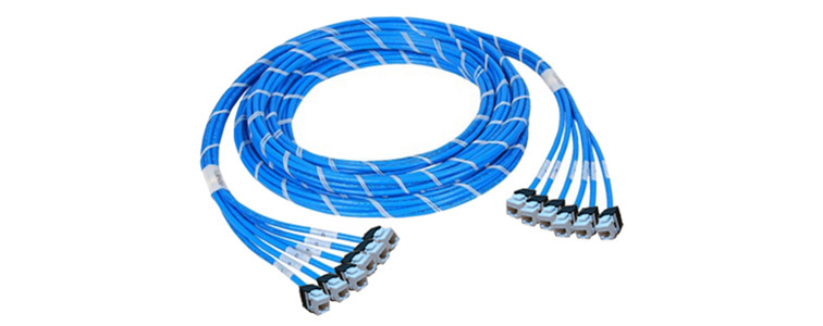
The following picture shows the outlook of a commonly used pre-terminated copper trunk cable, a 6 jack to 6 jack Cat5e UTP PVC copper trunk. The copper trunk cable, in simple, is a bound of individual copper cables which are factory pre-terminated. Without additional termination, cable installers can direct install copper cables. As the cables are bonded together, there is no need to worry about the cable mess.

6 jack to jack copper trunk cable

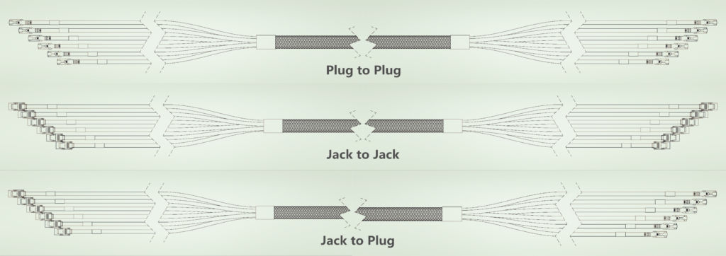
Various copper trunk cables are being provided for different requirements in practical applications. To select the proper copper trunk for your applications, there are three important factors to be considered. The first one is the copper cable type. Copper trunk cables using Cat5, Cat5e, Cat6 and Cat7 cables are all available in the market. The second factor is the cable count. The most commonly used copper cables usually have 6 or 12 cables in one bound. Higher or lower cable counts are also available. The third one is the termination type of the breakout legs of the copper trunk cables. The breakout legs are usually terminated with RJ45 plugs or jacks, some copper trunk cables might leave on end or both ends unterminated for customers to DIY according to their practical applications. The following picture shows three most commonly used copper trunk cables: plug to plug copper trunk cable, jack to jack copper trunk cable and jack to plug copper trunk cable.

copper trunk cable

How to Use Copper Trunk Cables?

The using of copper trunk cables can effectively reduce the installation time and increase the work performance of the copper network. What’s more, they are able to provide easy-to-manage cabling environments if being properly used. How to make full use of pre-terminated copper trunk cables? During cabling, it is always the case that the backbone cable should be interconnected work cross-connected before it is connected to the target device. The following shows three situations which are commonly seen for copper cabling using copper trunk cables.

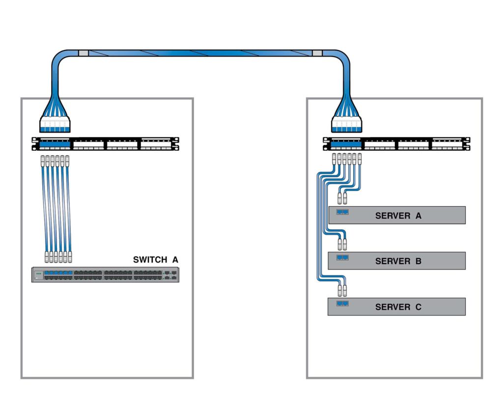
Two-connector Interconnect

In the first case (shown in the following picture), a 6 jack to 6 jack copper trunk cable is used to connect three servers to a switch. The copper patch panel is being used on each end of this connection. One is near the switch end and the other is near the server end. Copper patch cables are used to interconnect these devices.

copper cable interconnection
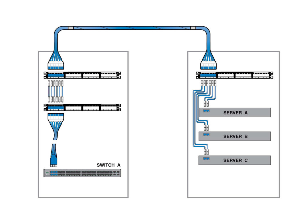
Three-connect Cross Connect

Cross-connect is also very common in the data center. The following picture shows a basic cabling structure of a three-connector cross connection. In this network, three RJ45 patch panel is being used. This structure is like the above mentioned two-connector interconnection. Just a cross-connecting process is added at the switch end.

cross connection
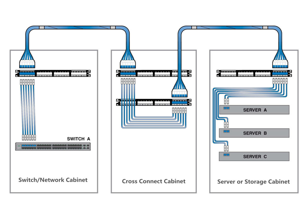
Four-Connector Cross Connect

The following shows a more complex network structure, which is a commonly used four-connector cross connection. This type of connection usually requires a patch field which is usually cabinet. In this case, two copper trunk cables are working as permanent cables. Patch cords are used at this cabinet to connect the devices. Four patch panels are used. There is an individual cabinet for cross connection.

cross connection

Conclusion

With the help of pre-terminated copper trunk cables, the cabling of the large data center or high density environment becomes easier and faster. It also simplifies cable management in data centers. Currently, there are a lot of vendors provided copper trunk cables. Some can also provide customized copper trunk cable according to your data center applications, which can reduce the waste of materials and help to build a more clean and neat cabling environment.

Related Articles:
Quick View of Ethernet Cables Cat5, Cat5e And Cat6
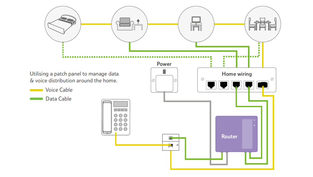
Home Ethernet Wiring Guide: How to Get a Wired Home Network?
How to Choose the Right Cat6a Cable for Your 10G Networks

10GBASE-CR VS 10GBASE-T

In the past decades, the telecommunication industry has changed a lot. A wide selection of transmission methods has been introduced. Fiber optic cables are widely used in today’s network. It seems that copper cables are out of fashion. However, there are still many advantages of using copper networks. Copper cables are stronger and easier to manage than fiber optic cables. The cost of copper cable is much lower than fiber optic cables. In addition, copper network is easier to build, which eliminating the process of I/O. Now, copper cables are able to support data rate of 1G, 10G, 40G and even 100G, among which 10G copper based network is most commonly deployed. Currently, there are two types of standards which are designed for 10G copper based network: 10GBASE-CR and 10GBASE-T. Which one should you choose if you want to build a 10G copper based network? This article offers the answer.

Comparison Between 10GBASE-CR and 10GBASE-T

Several significant factors should be considered during the selection between the 10GBASE-T and 10GBASE-CR, which area transmission distance, transmission media, module type and cost.

10GBASE-CR and 10GBASE-T Transmission Distance and Media

10GBASE-CR is invented before 10GBASE-T. 10GBASE-CR can support 10G data rate up to 10 meters over twinax cable. While 10GBASE-T can support a longer transmission up to 100 meters over Cat6a twisted copper pair.

10GBASE-CR and 10GBASE-T Transmission Interfaces

Small package form factors are adopted in both 10GBASE-CR and 10GBASE-T applications, to meet the requirement of high density. SFP+ form factor is most commonly used for 10GBASE-CR applications.

SFP+ passive direct attach cables and SFP+ active direct attach cables are usually used for 10GBASE-CR applications. The two SFP+ copper cables are terminated with a SFP+ module on each end. 10G SFP+ active direct attach twinax copper cable can reach a longer transmission distance than the passive one. The market now can provide a wide selection of SFP+ DACs for different types of switches and platform.

10G SFP+ copper cable

Network interface card with SFP+/XFP interfaces are often used for 10GBASE-T applications. Not all the vendors provide 10GBASE-T SFP+ modules. HP has provided a 10GBASE-T SFP+ module. However, compatibility of the modules is limited by the switch brand. This HP 10GBASE-T SFP+ module can only be used on HP switches. Thus, 10GBASE-T application is kind of limited for now.

10GBASE_T NIC
10GBASE-CR and 10GBASE-T Cabling Cost

Put transmission distance aside, the cost for 10GBASE-CR cabling is much lower for 10GBASE-T cabling. For instance, a HP 10GBASE-T SFP+ costs around $ 1000 USD. However, the price for a 10G HP SFP+ DAC is around $100 USD. This price is lower to $ 23 for a 1.2 meter HP JD096C compatible passive SFP+ DAC in FS.COM. Thus, 10GBASE-CR cost less than 10GBASE-T in general.

Conclusion

Generally, 10GBASE-T has the greatest advantages on transmission distances (up to 100m over Cat6a). Although, 10GBASE-CR can only reach up to 15 meters over twinax copper cable. It has great advantages on cable costs. In addition, most of our data center use for copper cabling are less than 15 meters, which means 10GABSE-CR can satisfy most requirement for copper cabling in data centers. Thus, 10GABSE-CR is suggested for most 10G copper cabling cases.

Build a Copper Network at Home

Broadband is becoming more and more important to our daily life. The Fiber to the Home (FTTH) is being widely deployed. Broadband provided by fiber optic cables is very common. However, most of our home devices are still having electrical interfaces like RJ45 interfaces. In addition, the copper network cable and technologies are keeping developing to satisfy the requirements of high data rate broadband. Thus, many people still have confidence in copper based network and would like to deploy a copper based network at home which is more cost-effective and easier to manage.

home networking

Factors to Consider Before Copper Home Network Deployment

To build a copper network at home is easier than that of a fiber optic based home network. But there are still a lot of things need to be considered. Before deploy the copper home network, you should firstly understand what you want from this copper home network. Of course, easier access to broadband and WiFi at everywhere are the most basic requirements. You should also decide the port number and expectation of the network performance, which will directly the decide product selection or cost of your network.

Three Steps to Build A Copper Home Network

There are mainly three steps to build a copper home network which will be introduced in the following part of this post.

distribution cable
Step One: Introduce Service Provider Distribution Cable to Your Home

Now most of the broadband service provider will install a distribution point near or inside a building. As shown in the above picture, copper network cables or fiber optic cables are deployed inside a building to bring services to every houses inside this building. For some old buildings, the cables between the end users and distribution point are still copper based. For many new buildings, these cables are usually fiber optic based. Just add an ONU (Optical Network Unit), you can change these optical signals into electrical signals and distribute signals to different ports and home devices. If your apartment is a small one, you can just use one ONU or router in the whole home network.

There are a variety of ONUs and routers which can support WiFi and satisfy various port requirements. For example, the following picture shows the application of a typical ONU (4FE+2POTS+WiFi) that can meet the requirement of most apartments. This ONU has a SC optical interface to be connected with the service provider’s entry fiber optic cable. Except two voice ports and four LAN ports, this ONU provides WiFi function.

4FE+2POTS+WiFi
Step Two: Wiring the Whole House

Wiring the whole house is very important for a home network with good broadband access. It is known that most home devices have better performance via a wired connection compared with being connected to WiFi. So during this process, you should device the port number you should leave in your house and how many devices should be connected to the network. Now there are a variety of home devices can be connected to a home network for better and smarter performance, which is also called smart home. Devices like air condition, light control and televisions can all be connected to the home network. Thus, copper network cable for signal transmission should have good and reliable performance. Cat6 and Cat7, two types of high performance Category copper cable, which can meet the requirement for both now and future, are strongly recommended.

home networking

The above picture shows the copper cabling for an apartment. The bedroom, living room, office and dining room of this house is all connected to broadband via copper network cable. In addition, each room is connected to voice cable ensuring that the house owner would not miss phone calls in most part of the house.

Step Three: Terminate Copper Cables and Connect Them to Home Devices

For the sake of security and reliability, the copper network cables should be terminated at wall plate ports. And a length of RJ45 copper network patch cable should be used to connect the port with target device as shown in the following picture.

copper home networking

FS.COM Copper Networking Solutions

Good access home network should combine the wired connection with WiFi connection. Right products can provide high performances. The above mentioned copper home networking products are all being provided in FS.COM. Copper networking products for data center are also available in FS.COM. Kindly contact sales@fs.com for more details, if you are interested.

G.fast Offers Fiber Speed Ethernet Over Copper

The demand for higher data rates is continuously increasing driven by the applications like Cloud Computing, Big Data and Internet of Things. Meanwhile, the strong market competition makes the network operators to improve the network architecture and deliver high speed services. Pure fiber network should be the best solution. There is no wonder that the fiber network is the trend of the future and it is gradually extended closer to users during the transition from copper-based access networks to pure fiber networks. However, it is not favorable to connect the fiber directly to the customer premises and the cost is high in some cases, like old buildings. To find the fast and cost-effective way to deliver Gigabit speed Ethernet, copper access technology is being applied in some cases. This technology is known as G.fast.

G.fast and FTTdp

G.fast, based on the latest VDSL technology including cross talk cancellation and re-transmission, is designed for use in a ‘last-mile’ of less than 250 meters. Combining the advantages of fiber optic access technology and copper access technology, G.fast can deliver data at fiber speed to the customers using telephone copper wires.

The problem with G.Fast is that its ultra-fast speeds only work over very short distances. To shorten the copper distance, FTTdp is usually applied with G.fast. “dp” here stands for “distribution point”. This solution brings the fiber optic cable out of street cabinets and moves it closer to home via the distribution point. The following network diagram shows the difference of FTTH and FTTdp using G.fast. The blue lines represent fiber optic cable, the red ones represent copper wire.

G.fast and HTTdp

G.fast Shifts the Limits of Copper

It seems that there is no need for copper access in building a FTTx connection. But in practice, connecting the fiber directly to the customer premises causes some disadvantages which can be solved by G.fast.

There might be many difficulties when deploying fibers to the user homes, especially some existing buildings. Sometime it is even not possible to deploy fibers to the user homes. In addition, most in-house telephone installations still rely on copper cables for most existing and newly constructed buildings because fibers are expensive and difficult to handle. There is no need to deploy fiber optic cable in building and home when delivering Gigabit Ethernet with G.fast.

The fiber optic based customers premises equipment (CPE) are usually installed by technician. Compared with fiber optic connections, copper-based CPE installation is simple. Just connecting the CPE to the telephone plug with the delivered cable would finish the installation, which can be installed by customer. Thus, G.fast can save the cost for new users and makes the home installation much easier.

Optical fibers can be broken or have transmission loses when wrapped around curves and optical fibers require more protection around the cable compared to copper. What’s more, the fault location from the CPE is not easy. It would cost more to maintain the fiber connections compared with copper connections achieved by G.fast.

G.fast Paves the Way to FTTH

At first glance, G.fast is limiting the transmission from copper to fiber. Actually, G.fast accelerates the deployment of fiber optic networks. It cost a lot of time and money to process the paperwork and get permission of the subscriber before deploying the fiber optic cable. The processing is complicated. Hardware foundation is the main advantages of G.fast which eliminates the need to rewire the whole building and still allows a noteworthy uplift in access speeds. Copper is everywhere in telecommunication network. The hybrid copper/fiber approach—G.fast making full use of the telephone wires in the buildings actually makes the customers closer to optical fibers in time save and cost save manners. In this way, the transmission from copper to fiber is actually being promoted by G.fast.

Weighing time, broadband speed and cost, operators figure out that applying G.fast in FTTH is an economical and time-saving way to bring Gigabit speed Ethernet to the users. To capture market share of broadband service, some network operators are considering to use G.fast. Alcatel-Lucent and communications services company BT have already started a consumer trial of G.fast technology in Gosforth (situated in North-Eastern England), for offering ultra-broadband access to consumers.

Source: http://www.fs.com/blog/delivering-gigabit-ethernet-with-g-fast.html

The Core Technology Of WIRING

1. High-precision Optical Time Domain Reflectometer(ODTR)

OTDR technology through sending a test signal in the measured line while monitoring signal in the line of reflection phase and intensity. If the signal through the cable encounter mutation of an impedance, part or all of the signals will be reflected back, the reflected signal delay, size and polarity indicate the discontinuity position and feature of the special impedance in the cable.

2. Split Pairs

UTP(Unshielded Twisted Pair) cable is two insulated Network Cables twisted together to each other by a certain density, which reduces the degree of signal interference, each wire in the transmission of radiation waves are offset by radio waves from the other line.

The so-called split pairs is the original two pairs are opened and yet again to reform a new pair. Because when this failure occurs, the end-to-end connectivity is good, so use a multimeter or hand tool such tools can not check it out. Only with a dedicated cable tester to check it out. Since crosstalk on the related lines of no kink, so online pairs when signal through will produce a high near-end crosstalk (NEXT).

Split pairs normally also be used, but often crosstalk index is large, only to run in the 10M application, can not achieve the 100M application.

3. The Standard Twisted Pair Terminations

Twisted pair eight lines are inserted into the plug (or termination) according to the standard. There are two termination criteria: EIA/TIA T568A/T568B, no essential difference between them, but the difference between color. The natural problem of termination is to ensure that: 1, 2 are a pair; 3, 6 are a pair; 4, 5 are a pair; 7, 8 are a pair. Note: Do not one cable end with T568A, but the other end with T568B. The mix use of T568A/T568B is a special connection method of cross connection. Projects more use T568B wire method.

In Ethernet, Pin1, Pin2 is a twisted pair responsible for network data transmission, Pin3, pin6 is a twisted pair responsible for network data reception, so 1, 2 a pair, 3, 6 a pair, 4, 5 a pair, 7, 8 a pair, it is a must, and not 1, 2, 3, 4, 5, 6, 7, 8 pairs, so called split pairs, will lead to serious signal leakage.

4. Wire Map

Ware Map: This is to confirm the integrity of link connection, mainly to check each pair of 8-core Twisted Pair Cable whether meets the required standards EIA/TIA- 568A/568B, whether the wire at both ends of cable is matching. If wrong, there are five cases include open circuit, short circuit, crossed pairs, reversed pair and split pairs.

● Open circuit: refers to the phenomenon of line off, generally due to bad crystal head cable connection, common with the cable test equipment can locate the fault point.

● Short circuit: refers to one or more wires touch each other in a metal core, resulting in a short circuit.

● Crossed pairs: refers to wire at both ends error in the routing process, which is one end with 568A and the other end with the 568B, usually such wire method used in network equipments level, or network cards connection, but as a general wiring to say, as long as the two ends of the wire method consistent, as for the module wire method can refer to the color above.

● Reversed pairs: this error is due to both ends of a pair line connected to the positive and negative error, is generally believed that the odd line number for the positive electrode, the even line as the negative electrode, for example, 568B Pin1 orange white lines to the first pair of positive, Pin2 Orange Line is negative, it can form a direct current loop, reverse connection is positive and negative confused in the same pair line.

● Split pairs: this is one of the common wire error, which is not strictly comply with wire standard, it is specified in the standard that 1, 2 is the first pair, 3, 6, is the second pair, if 3, 4 into the second pair will cause large signal leakage, which produces NEXT (near end crosstalk), this will cause the user’s Internet difficulties or indirect interrupts, especially in the 1000Mbps network it is particularly obvious.