Category Archives: Fiber Optic Transmission

Upgrade to High Data Rate Transmission With Parallel Optic

Parallel optic represents a type of optical communication technology as well as the devices on either end of the link that transmit and receive information which are also known as parallel optical transceivers. Compared with traditional optical communication, parallel optic communication employs a different cabling structure for signal transmitting aiming at high-data transmission for short reach multimode fibers that are less than 300 meters. Traditional fiber optic transceivers cannot satisfy the increasing demand for high speed transmission, like 40GbE, while parallel optics technology can be a cost effective solution for 40/100GbE transmission.

Comparison between parallel optic technology and the traditional serial optical communication would better explain what parallel optic is and the reason why it is a cost effective solution to high data rate transmission. The following of this article will offer the comparison between the two optical communication technology from two aspects: connectivity method and key components.

Connectivity Method of Parallel Optic

Literally, parallel optics and serial optics transmit signals in different ways. In traditional serial optical communication, on each end of the link, there are one transmitter and one receiver. For example, the transmitter on End A communicates to the receiver on End B, sending a single stream of data over a single optical fiber. And a separate fiber is connected between the transmitter on End B and the receiver on End A. In this way, a duplex channel is achieved by two fibers.

2-fiber duplex connection

While in parallel optic communication, duplex transmission is achieved in a different way. A signal is transmitted and received through multiple paths, thus, the parallel optical communication can support higher data rate than the traditional optical communication. This is because, the devices for parallel optic communication on either end of the link contain multiple transmitters and receivers. For instance, in 2010 IEEE 802.3ba approved the 40GBASE-SR4 physical-medium-dependent multimode parallel optical solution, which uses eight fibers to transmit four duplex channels each at 10 Gigabit Ethernet. In this case, four 10Gbps transmitters on End A communicate with four 10Gbps receivers on End B, spreading a single stream of data over four optical fibers at a total data rate of 40Gbps.

Key Components of Parallel Optic

The parallel optical communication transmitting signals over multiple fibers, which has great advantages over traditional serial optical communication. It also means that it requires different components to support its high data rate transmission.

Connector: As previously mentioned, duplex transmission in serial optical communication uses 2-fiber duplex connectors, like duplex LC connectors to link the optics with other devices, while in parallel optical communication, multi-fibers are used to reach a higher data rate. Thus, multi-fiber connectors, like 12-fiber MPO connectors are used to connect with other devices. MPO connector is one key technology support parallel optical communication. This connectivity method is showed in the following picture?(Tx stands for transmit; Rx stands for receive).

12-fiber MTP parallel connection

Optical transceiver light source: Another complementary technology for parallel transmission is the light source of parallel optics—VCSELs (Vertical Cavity Surface Emission Lasers). Comparing with the edge-emitting semiconductor lasers in the traditional optics, VCSELs have better formed optical output which enables them to couple that energy into optical fibers more efficiently. In addition, VCSELs emit from the top surface, they may be tested while they are part of a large production batch (wafer), before they are cut into individual devices, which dramatically lowers the cost of the lasers. The following chart is about the comparison between VCSELs and edge-emitting semiconductor lasers. Cheaper to manufacture, easier to test, less electrical current required, supporting higher data rate, parallel optics using VCSELs could be a better choice to reach 40/100GbE transmission compared with traditional serial optics.

VCSEL vs Edge-Emitting Laser
Feature VCSEL Edge-Emitting Laser
Power consumption 2-3 mW 20 mW
Beam quality/ease of coupling Better, round low divergence Fine, asymmetric
Speed 10 Gbps 1 Gbps
Temperature stability 0.06 nm/oC 0.25 nm/oC
Specral width 1 nm 1-2 nm
Speckle Low in an array High


Parallel Optic for 40/100GbE Transmission

IEEE has already included physical layer specifications and management parameters for 40Gbps and 100Gbps operation over fiber optic cable. Two popular parallel optic solutions for 40Gbps and 100Gbps over multimode fibers are introduced here. For 40G, 40GBASE-SR4 transceiver is usually used, which requires a minimum of eight OM3/OM4 fibers for a transmit and receive link (4 fibers for Tx and 4 fibers for Rx). 100GBASE-SR10 transceiver is for 100Gbps transmission, which requires a minimum of 20 OM3/OM4 fibers for a Tx/Rx link, 10 fibers are used for Tx and the other 10 are for Rx.

40BASE-SR4 and 100BASE-SR10

Conclusion

The capabilities and uses of parallel optic and MPO technology continue to evolve and take shape as higher-speed fiber optic transmission, including 40/100GbE. It is uncertain that parallel optical communication would be the trend in the future. However, many cabling and network experts have pointed out that parallel optical communication supported with MPO technology is currently a way to equip an environment well prepared for the 40/100GbE transmission.

Source:
http://www.fs.com/blog/upgrade-to-high-data-rate-transmission-with-parallel-optics.html

Understanding MPO Cable and Polarity

MPO/MTP technology, which is of high density, flexibility and reliability with scalable, upgradeable properties, is one of the contributors that lead the migration to 40/100GbE. However, the network designers face another challenge which is how to assure the proper polarity of these array connections using multi-fiber MPO/MTP components from end-to-end. Maintain the correct polarity across a fiber network ensures that a transmit signal from any type of active equipment will be directed to receive port of a second piece of active equipment – and vice versa. To ensure the MPO cable work with correct polarity, the TIA 568 standard provided three methods, which will be introduced in this article.

MPO Connector

To understand the polarity in 40/100 GbE Transmission, the key of MPO technology—MPO cable connector should be first introduced. MPO connector usually has 12 fibers. 24 fibers, 36 fibers and 72 fibers are also available. Each MTP connector has a key on one of the flat side added by the body. When the key sits on the bottom, this is called key down. When the key sits on top, this is referred to as the key up position. In this orientation, each of the fiber holes in the connector is numbered in sequence from left to right and is referred as fiber position, or P1, P2, etc. A white dot is additionally marked on one side of the connector to denote where the position 1 is. (shown in the following picture) The orientation of this key also determines the MPO cable polarity.

MPO cable connector

Three Cables for Three Polarization Methods

The three methods for proper polarity defined by TIA 568 standard are named as Method A, Method B and Method C. To match these standards, three type of MPO truck cables with different structures named Type A, Type B and Type C are being used for the three different connectivity methods respectively. In this part, the three different cables will be introduced firstly and then the three connectivity methods.

MPO Trunk Cable Type A: Type A cable also known as straight cable, is a straight through cable with a key up MPO connector on one end and a key down MPO connector on the opposite end. This makes the fibers at each end of the cable have the same fiber position. For example, the fiber located at position 1 (P1) of the connector on one side will arrive at P1 at the other connector. The fiber sequence of a 12 fiber MPO Type A cable is showed as the following:

Type A MTP Cable

MPO Trunk Cable Type B: Type B cable (reversed cable) uses key up connector on both ends of the cable. This type of array mating results in an inversion, which means the fiber positions are reversed at each end. The fiber at P1 at one end is mated with fiber at P12 at the opposing end. The following picture shows the fiber sequences of a 12 fiber Type B cable.

Type B cable

MPO Trunk Cable Type C: Type C cable (pairs flipped cable) looks like Type A cable with one key up connector and one key down connector on each side. However, in Type C each adjacent pair of fibers at one end are flipped at the other end. For example, the fiber at position 1 on one end is shifted to position 2 at the other end of the cable. The fiber at position 2 at one end is shifted to position 1 at the opposite end etc. The fiber sequence of Type C cable is demonstrated in the following picture.

Type C Cable

Three Connectivity Methods

Different polarity methods use different types of MTP trunk cables. However, all the methods should use duplex patch cable to achieve the fiber circuit. The TIA standard also defines two types of duplex fiber patch cables terminated with LC or SC connectors to complete an end-to-end fiber duplex connection: A-to-A type patch cable—a cross version and A-to-B type patch cable—a straight-through version.

Duplex patch cable

The following part illustrates how the components in MPO system are used together to maintain the proper polarization connectivity, which are defined by TIA standards.

Method A: the connectivity Method A is shown in the following picture. A type-A trunk cable connects a MPO module on each side of the link. In Method A, two types of patch cords are used to correct the polarity. The patch cable on the left is standard duplex A-to-B type, while on the right a duplex A-to-A type patch cable is employed.

Method A

Method B: in Connectivity Method B, a Type B truck cable is used to connect the two modules on each side of the link. As mentioned, the fiber positions of Type B cable are reversed at each end. Therefore standard A-to-B type duplex patch cables are used on both sided.

Method B

Method C: the pair-reversed trunk cable is used in Method C connectivity to connect the MPO modules one each side of the link. Patch cords at both ends are the standard duplex A-to-B type.

Method C

Conclusion

Network designer using MPO/MTP components to satisfy the increasing requirement for higher transmission speed, during which one of the big problems—polarity, can be solved by selecting the right types of MPO cables, MPO connectors, MPO cassette and patch cables. The three different polarization methods can be applied according to the satisfy requirements in different situations. For more information about polarity in MPO systems and 40/100GbE transmission polarity solutions, please visit Fiberstore tutorial at “Polarity and MPO Technology in 40/100GbE Transmission“.

Related articles: Understanding Polarity in MPO System

                             Introduction to MTP Connector and MPO Connector

G.fast Offers Fiber Speed Ethernet Over Copper

The demand for higher data rates is continuously increasing driven by the applications like Cloud Computing, Big Data and Internet of Things. Meanwhile, the strong market competition makes the network operators to improve the network architecture and deliver high speed services. Pure fiber network should be the best solution. There is no wonder that the fiber network is the trend of the future and it is gradually extended closer to users during the transition from copper-based access networks to pure fiber networks. However, it is not favorable to connect the fiber directly to the customer premises and the cost is high in some cases, like old buildings. To find the fast and cost-effective way to deliver Gigabit speed Ethernet, copper access technology is being applied in some cases. This technology is known as G.fast.

G.fast and FTTdp

G.fast, based on the latest VDSL technology including cross talk cancellation and re-transmission, is designed for use in a ‘last-mile’ of less than 250 meters. Combining the advantages of fiber optic access technology and copper access technology, G.fast can deliver data at fiber speed to the customers using telephone copper wires.

The problem with G.Fast is that its ultra-fast speeds only work over very short distances. To shorten the copper distance, FTTdp is usually applied with G.fast. “dp” here stands for “distribution point”. This solution brings the fiber optic cable out of street cabinets and moves it closer to home via the distribution point. The following network diagram shows the difference of FTTH and FTTdp using G.fast. The blue lines represent fiber optic cable, the red ones represent copper wire.

G.fast and HTTdp

G.fast Shifts the Limits of Copper

It seems that there is no need for copper access in building a FTTx connection. But in practice, connecting the fiber directly to the customer premises causes some disadvantages which can be solved by G.fast.

There might be many difficulties when deploying fibers to the user homes, especially some existing buildings. Sometime it is even not possible to deploy fibers to the user homes. In addition, most in-house telephone installations still rely on copper cables for most existing and newly constructed buildings because fibers are expensive and difficult to handle. There is no need to deploy fiber optic cable in building and home when delivering Gigabit Ethernet with G.fast.

The fiber optic based customers premises equipment (CPE) are usually installed by technician. Compared with fiber optic connections, copper-based CPE installation is simple. Just connecting the CPE to the telephone plug with the delivered cable would finish the installation, which can be installed by customer. Thus, G.fast can save the cost for new users and makes the home installation much easier.

Optical fibers can be broken or have transmission loses when wrapped around curves and optical fibers require more protection around the cable compared to copper. What’s more, the fault location from the CPE is not easy. It would cost more to maintain the fiber connections compared with copper connections achieved by G.fast.

G.fast Paves the Way to FTTH

At first glance, G.fast is limiting the transmission from copper to fiber. Actually, G.fast accelerates the deployment of fiber optic networks. It cost a lot of time and money to process the paperwork and get permission of the subscriber before deploying the fiber optic cable. The processing is complicated. Hardware foundation is the main advantages of G.fast which eliminates the need to rewire the whole building and still allows a noteworthy uplift in access speeds. Copper is everywhere in telecommunication network. The hybrid copper/fiber approach—G.fast making full use of the telephone wires in the buildings actually makes the customers closer to optical fibers in time save and cost save manners. In this way, the transmission from copper to fiber is actually being promoted by G.fast.

Weighing time, broadband speed and cost, operators figure out that applying G.fast in FTTH is an economical and time-saving way to bring Gigabit speed Ethernet to the users. To capture market share of broadband service, some network operators are considering to use G.fast. Alcatel-Lucent and communications services company BT have already started a consumer trial of G.fast technology in Gosforth (situated in North-Eastern England), for offering ultra-broadband access to consumers.

Source: http://www.fs.com/blog/delivering-gigabit-ethernet-with-g-fast.html

What’s the Difference Between Transceiver & Transponder?

In a fiber optic communication network, there are many equipment and facilities to support the normal operation of the system. Fiber optic transponder and fiber optic transceiver are the one of these devices. Literally, both of them are with a prefix “trans”. It seems to imply that there is a similarity between them. Actually, they are not the same. So, what’s the difference between them, something difference on principle or applications? Today, we are going to have a discussion on this topic.

First, in order to better understand the difference between a fiber optic transceiver and a fiber optic transponder, we need to define what each one does.

Fiber Optic Transceiver
Most systems use a “transceiver” which includes both transmission and receiver in a single module. Its purpose, in broad terms, is to transmit and receive data. In fiber optic communication, the commonly used transceiver modules are hot-swappable I/O (input/output) devices which plug into module sockets. The transceiver acts to connect the electrical circuitry of the module with the optical or copper network. Devices such as routers or network interface cards provide one or more transceiver module slot (e.g GBIC, SFP, XFP), into which you can insert a transceiver module which is appropriate for that connection. The optical fiber, or wire, plugs into a connector on the transceiver module. There are multiple types of transceiver module available for use with different types of wire, fiber, different wavelengths within a fiber, and for communication over different distances. The most commonly used fiber optic transceivers include GBIC, SFP, SFP+, XFP, CFP, QSFP etc. They are widely used for different application, eg. 10G, 40G fiber optic transmission.

Fiber Optic Transponder
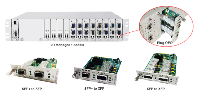
“Transponder” includes a transmitter and a responder. It is a similar device with transceiver. In optical fiber communications, a transponder is the element that sends and receives the optical signal from a fiber. A transponder is typically characterized by its data rate and the maximum distance the signal can travel. According to its specific applications, it is also known as wavelength-converting transponder, WDM transponder or fiber to fiber media converter. Fiber optic Transponders extend network distance by converting wavelengths (1310 to 1550), amplifying optical power and can support the “Three Rs” to Retime, Regenerate and Reshape the optical signal. In general, there is an O-E-O (optical-electrical-optical) function with this device. Fiber optic transponders and optical multiplexers are usually present in the terminal multiplexer as an important component for WDM (Wavelength Division Multiplexing) system. In addition, in nowadays market, many transponders are designed as protocol and rate-transparent fiber media converters that support SFP, SFP+ and XFP transceivers with data rates up to 11.32 Gpbs, and with seamless integration of different fiber types by converting multi-mode fiber to single-mode fiber, and dual fiber to single-fiber.

2U fiber Optic Transponder

Fiber Optic Transceiver vs Fiber Optic Transponder
A transponder and transceiver are both functionally similar devices that convert a full-duplex electrical signal in a full-duplex optical signal. The difference between the two is that fiber transceivers interface electrically with the host system using a serial interface, whereas transponders use a parallel interface. So transponders are easier to handle lower-rate parallel signals, but are bulkier and consume more power than transceivers. In addition, transceivers are limited to providing an electrical-optical function only (not differentiating between serial or parallel electrical interfaces), whereas transponders convert an optical signal at one wavelength to an optical signal at another wavelength. As such, transponders can be considered as two transceivers placed back-to-back.

Author’s Note
I hope you can start down the path to fully understanding transceivers, transponders, and the difference between them, particularly in a networking, Ethernet, or fiber-optic communications setting after reading this article. Of cause, knowledge is endless, if you still want to get more information about transceiver and transponder, I suggest that you should find more references to read. If you just need to buy the related products, I will recommend Fiberstore to you as usual.

Article Source: http://www.fiber-optic-transceiver-module.com/whats-the-difference-between-transceiver-transponder.html

How to troubleshoot the glitch of the Video Fiber Extender Quickly

If you have a video fiber extender, you may sometimes find it doesn’t work as expected, expecially the first time you connect it. Such questions as not working properly, or optical light is not on etc. In a word, there will be some technical issues need to be consulted after you have connected the video fiber extender or during testing. It is inconvenience to define the problems due to the geographical limitations so that sometimes a simple problem has to spend a lot of time and effort. For the convenience of our customers, Fiberstore summarize some past experiences of solving the problems on video fiber extender and tell you how to troubleshoot the glitch of the Video Fiber Extender Quickly during your installation and testing. Let’s explore together in this paper.

Reception Problem of Electrical Signals
When we meet this problem, we always use the alternative method for fast troubleshooting. Specific methods are as follows:

Firstly, we should confirm that power supply is normal, and then ensure the entire signal whether is connected correctly. After the above two steps, if it is still no a display screen, we could disconnect the fiber optic connector end of the device and remain cables and power unchanged. If the creen displays ”snow”after the fiber being disconnected, it indicate the optical fiber connections is normal before disconnecting the fiber. In general, “snow” may also states that screen works normally. Receiver not receiving a sufficient amount of an optical signal may occurs this issue. Please try to connect the fiber to the receiver again. If the screen is still black, we could confirm that the video fiber extender has no video input signal or is wrong by itself.

On the other hand, we should check the video input on the transmitter. Firstly, disconnect the signal source from the optical transmitter, and connected it to the screen directly with a video cable. If the screen is working, replace the optical transmitter. If in the case of fiber disconnected, the screen remains blank, you need to check whether all connections of the screen are correct. If all connections are no problem, replace the receiver or screen and have a try.

About the “snow”, there are some method to deal with. If there is “snow” in the video images, detect optical power into the receiver with an optical power meter. If the optical power in line with the requirements of the receiver, there may be a problem of the receiver. Replace the receiver and have another try untill you solve the problem. If the problem still exist, replace the transmitter and have a try. If the optical power of the receiver below the calibration value, you could check the transmitter light output with a power meter and fiber optic jumpers. If the output meets the specifications, it may be an optical fiber or optical connector problem. Clean the optical connector and verify that you make the correct choice of optical transmitters based on the type and length of the optical fiber connection. If the light output is still low, you should replace the transmitter.

Control Problem of Video Optic Extender to Camera Connection
Firtly, we should confirm that video fiber extender works normally which indicates that the fiber is available. The bigger the fiber attenuation, the greater the loss of video is than the lost control data of PTZ. Before PTZ control signal transmission, check TD (data activity) LED light on the receiver. Normal situation is that when the data transfer, the indicator light or flash following your operation. If it is not, the problem source will be the receiver. The problem will be obvious when you get a replacement of a same type of receiver.

If you still have any question with your Fiberstore’s video fiber extender and can’t solve it according to this paper, you could contact us by log in our website: www.fs.com or send E-mail to us. Fiberstore is always your good alternative for your video fiber extender demands.