Category Archives: WDM Optical Network

DWDM MUX/DEMUX Insertion Loss Test

During the selection of a DWDM MUX/DEMUX, the insertion loss should always be considered. Generally, a report including the insertion loss value of each port on the DWDM MUX/DEMUX, is usually attached with the product. These values are tested by professional testers. This post will illustrate how to test the insertion loss of DWDM MUX/DEMUX by using an easy-to-get optical power meter.DWDM MUX insertion loss test

Products Required for Insertion Loss Test

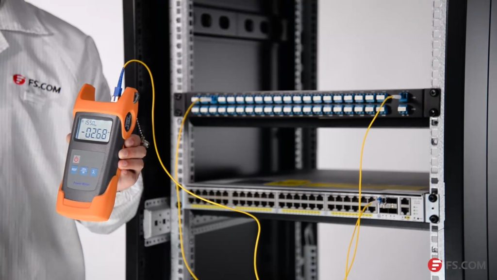
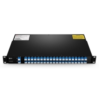
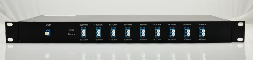
We will use 
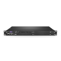
Cisco Catalyst 4948E switch and Cisco compatible DWDM SFP+ modules as light source to test the insertion loss of a 
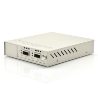
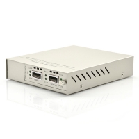
40-CH DWDM MUX/DEMUX
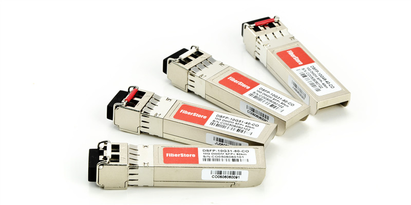
 provided by FS.COM. This DWDM MUX/DEMUX has a typical insertion loss of 3.0 dB. Channel 25 port and Channel 60 port will be tested. The products and tools required are listed as following:

DWDM MUX/DEMUX Insertion Loss Test Steps

First, install the 80km C25 DWDM SFP+ module in the SFP+ port of Cisco Catalyst 4948E. Second, connect the Tx port of the SFP+ module to the Rx port of Channel 25 port with a length of LC-LC simplex single-mode patch cable. Then, connect the TX port of the COM port to the optical power meter with a length of LC-SC simplex single mode patch cable.

Please note to clean all the optical interfaces before connecting to ensure the accuracy of the testing result. The connection is shown in the following picture.

DWDM insertion loss test

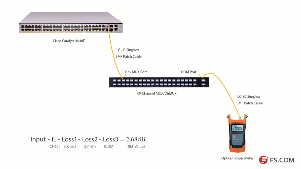
Press the λ button to select the wavelength of 1550nm. Then, we will get the optical power value (2.68dB) of the signal from C25 80km DWDM SFP+ module. Light loss occurs when the optical signal pass LC-LC simplex SMF patch cable (Loss1), CH25 port, LC-SC simplex SMF patch cable (Loss2) and COM port (Loss 3) as shown in the above picture.

We get a simple formula here:

Input power – Insertion Loss (CH25) – Loss1-Loss2 -Loss3 = 2.68dB (REF value)

If we want to get the insertion loss value of Channel 25, the formula will be:

Insertion Loss (CH25) = Input power – Loss1 -Loss2 -Loss3 – 2.68dB (REF value)

We can set the 2.68dB as the reference value. And if we can test the optical power value of the channel 25 SFP+ after it experienced these three loss points, the difference value will be the insertion loss of the channel 25 channel port.

DWDM insertion loss test

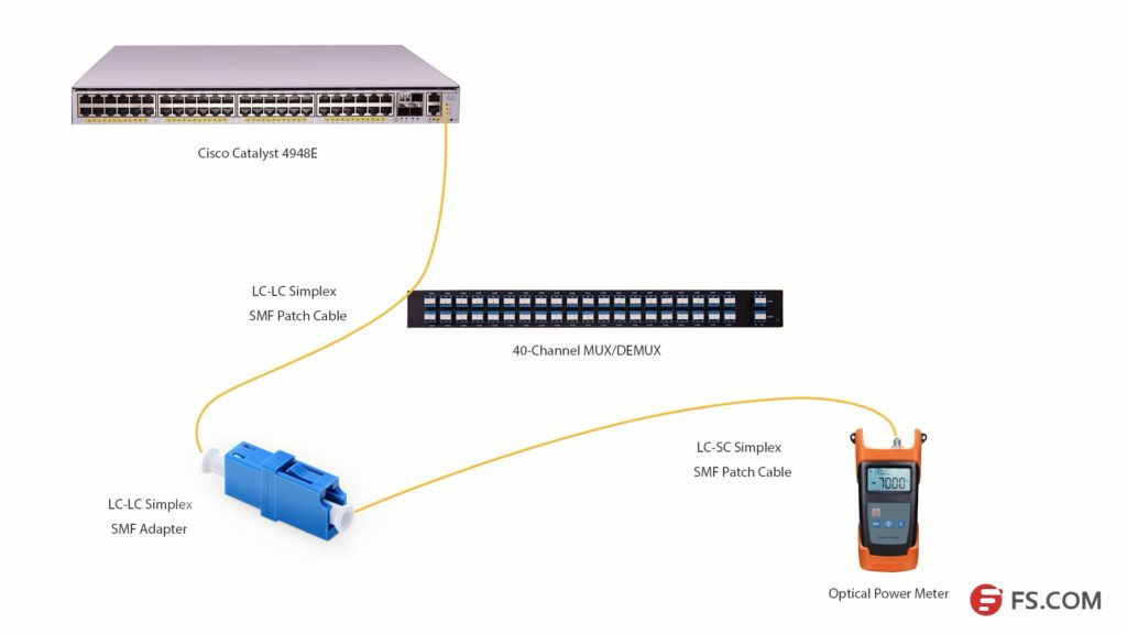
As the com port could be regarded as an adapter, we will use an adapter to connect the LC-SC and LC-LC patch cables together. Then, connect them to the optical power meter as shown in the above picture, we can get the difference value which is 3.58dB. This value is the insertion loss of the Channel 25 port on this 40Ch DWDM MUX/DEMUX. This value might not be very accurate value, but it is close to it.

DWDM MUX/DEMUX Insertion Loss Testing Video


We have taken a video about how to test the 40CH DWDM MUX/DEMUX insertion loss with optical power meter. You can get more details in this video. All the products and tools in this video are provided by FS.COM. Kindly contact sales@fs.com or visit FS.COM for more if you are interested.

OEO 3R Converter Instruction

Optical signals are transmitted on specific wavelengths like 850nm, 1310nm, 1550nm and CWDM wavelengths and DWDM wavelengths. In some cases, it occurs that you need to converter a wavelength of optical signals into another wavelength for transmission. A useful component OEO 3R converter is suggested to be used. The OEO converter is also known as transponder OEO. This component uses the Optical-Electrical-Optical principle to offer the conversion between different wavelengths of optical signals. “3R” means re-timing, re-shaping, and re-amplifying.

OEO 3R

OEO 3R Converter for Wavelength Conversion

OEO 3R converter can fit various applications and can be installed in the network flexibly. It is a very popular component in DWDM and CWDM networks. In many situations, we are using fiber optic transceiver that working on 850nm, 1310nm and 1550nm for optical signal transmission. However, if you want to add optical signals of these wavelengths into a CWDM or DWDM network, you should firstly convert the wavelengths into CWDM or DWDM wavelengths. With OEO converter, this could be easy. The following picture shows a case which uses OEO converter in a CWDM network for wavelengths conversion.

OEO WDM

In this case, a 10G SFP+ to SFP+ OEO with two SFP+ ports, is being used for wavelength conversion between 1310nm and CWDM wavelength 1610nm. A 10G-LR SFP+ module working on 1310nm is used in a 10G switch on site A. To add the optical signal of this port in to the existing CWDM network, this module is being connected to another 10G LR SFP+ module which is being inserted in the SFP+ Port 1 of the OEO converter. A CWDM 1610nm SFP+ module, connected to the CWDM MUX/DEMUX on site B, is being used in the other port of this OEO converter. The OEO converter the 1310nm signal into 1610nm CWDM signal. The optical signal from site A is being added into the CWDM network via the CWDM MUX/DEMUX on site B.

OEO 3R Converter for Fiber Mode Conversion and Fiber Repeating

The using of OEO converter for wavelength conversion is simple. As above mentioned, the OEO 3R converter has the function of re-timing, re-shaping, and re-amplifying, the OEO 3R converter can also be used as fiber mode converter and fiber repeater converters. The following picture shows another case with OEO 3R converter working as fiber repeater and providing conversion between single-mode and multimode.

OEO 3R

In this case, three SFP+ to SFP+ OEO converters are deployed between Site A and Site B for long distance dual-way optical transmission. The optical signal from Site A is firstly converted from multi-mode fiber into single-mode fiber for 90km transmission by one OEO converter. Then, a second OEO converter is used as a repeater to “3R” the optical signals. After that, the single-mode signal will travel another 75km. Before the signal reaches the switch in Site B, another OEO converter converts the single-mode signal into multimode signal.

OEO Converter Options

OEO converters provide flexible solution for optical transmission network. Except the above mentioned 10G SFP+ to SFP+ OEO converter, there are many other OEO converters with different port types, port counts and designs. The following table listed several OEO converters for your reference.

 SFP+ to SFP+ OEO  XFP OEO
SFP+ to SFP+ OEO Converter XFP to XFP OEO Converter
 QSFP+ OEO  8 SFP+ OEO
QSFP+ to QSFP+ OEO Converter 8 Ports SFP+ 10G OEO Converter

Differences Between Pre-Amplifier, Booster Amplifier and In-line Amplifier

Transmission distance has always been a key factor during deployment of fiber optic network. DWDM technologies, which are considered as the most cost-effective ways to increase the network capacity over long transmission distance, have been widely applied in our telecommunication network. To further extend the transmission distance of optical signals transmission from the DWDM fiber optic transceivers, optical amplifiers are usually used in the DWDM network. Different types of optical amplifiers have been invented to meet the signal amplifying requirements in different situations. This post will introduce the differences between the three most commonly used optical amplifiers: pre-amplifier, booster amplifier, and in-line amplifier.

Basics of Optical Amplifier

In the past, if you want to extend the transmission distance of DWDM network, an optical regenerator station is required to be installed in the fiber link every 80km to 100km. The regenerator station will electronically regenerate the optical signals to overcome the power loss and ensure that the optical signal can be detected at the receiver end. However, this requires a lot of money and is not easy to upgrade the whole network.

With optical amplifier, things become much easier. The optical amplifier can enlarge the optical signals without regeneration. In addition, the network upgrading is more cost-effective with optical amplifier. Each optical amplifier has an important factor which is operation gain measured in dB. The operation gain of the optical amplifier should be carefully calculated to ensure network performance. Pre-amplifier, booster amplifier and in-line amplifier are used in different places in the fiber optic network. And they support different operation gains according to the whole network requirement.

Pre-Amplifier, Booster Amplifier and In-line Amplifier

Pre-Amplifier is usually installed at the receiver end of the DWDM network to amplify the optical signal to the required level to ensure that it can be detected by the receiver. The following picture shows a typical diagram for a duplex 10G DWDM network that can support 80km. A pre-amplifier is installed at each receiving end of this network. There will be great power loss after the optical signal goes through the 80km optical fiber. Then, a pre-amplifier installed at the receiver end is necessary. Generally, a pre-amplifier should offer high gain to ensure that the optical signal is detectable.

pre-amplifier

Booster Amplifier is installed in the transmitting end of the fiber optic network, which can amplifier amplify the optical signal launched into the fiber link. It is usually used in DWDM network where the multiplexer attenuates the signal channels. The following picture shows a 10G DWDM network using booster amplifier (BA) at the transmitting end and pre-amplifier (PA) at receiving end. Thus, this 10G DWDM network can support a transmission distance much longer than the above-mentioned one. Please note, a DCM (Dispersion Compensation Module) is added in this network to further ensure the transmission quality. A booster amplifier usually provides low gain and high output power.

booster amplifier

In-line Amplifier is easy to understand. The gain provided by the pre-amplifier and booster amplifier might not be enough due to the optical loss caused by long haul transmission. In-line amplifier is installed in the fiber optic link every 80-100km as shown in the following picture. It has moderate gain and has similar output power to those of booster amplifier.

in-line amplifier

Conclusion

The optical amplifier can help to amplifier the optical power during long haul transmission to ensure that the receiver can detect the optical signal without error. Three amplifiers are commonly used in DWDM network. Booster amplifier is used to amplifier optical power at the transmitting end and pre-amplifier is placed at the receiver end. If the transmission distance is longer than 150km or have great power loss during transmission, in-line amplifier is suggested to be installed every 80km to 100k in the fiber optic link. The gain of these amplifiers should be carefully calculated during practical use. Kindly visit DWDM EDFA Amplifier page for more details.

Related Article: Introduction of Optical Amplifier

Related Article: Optical Amplifier – EDFA (Erbium-doped Fiber Amplifier) for WDM System

How to Extend Transmission Distance in DWDM Network?

DWDM network has been widely accepted as the most cost-effective and feasible solution to increase the fiber optic network capacity over long distance. Except the bandwidth, the transmission distance is also an important factor during the deployment of DWDM network. This post is to introduce how to ensure and extend the transmission distance in DWDM network.DWDM MUX/DEMUX

Proper DWDM Fiber Optic Transceiver Is Essential

Generally, the fiber optic transmission distance is affected by the data rate, light loss, light source, etc. During the deployment, technicians usually need to select proper fiber optic transceivers to ensure the light source is strong enough to support the long transmission distances. For instance, 1G DWDM SFP modules provided by the market can usually support transmission distance up to 100km, while for 10G DWDM SFP+ modules this distance decrease to 80km. If the longer transmission distance is to achieve, proper fiber optic devices should be added in the DWDM network to ensure the transmission quality. The following part will take the examples of 10G DWDM network which uses DWDM SFP+ modules supporting transmission distance up to 80km on both ends of the fiber link. This 10G DWDM network will be required to support fiber optic links up to 40km, 80km, 120km and 200km separately.DWDM SFP+

Case Study One: 40km DWDM Network

In this first case, this 10G DWDM network is required to support 40km transmission distance. As we are using the 80km DWDM SFP+ modules, if there are no other locations deployed between the two ends of this network, generally no other devices are required to be installed between the two DWDM MUX/DEMUXs. The light source of 80km DWDM SFP+ modules can support 10G transmission over 40km.40km DWDM network

Case Study Two: 80km DWDM Network

If this DWDM network is required to support 80km transmission distance, we will still use the 80km DWDM SFP+ modules. The light source of these 80km DWDM SFP+ modules might not be able to support such long transmission distance, as their might have light loss during transmission. In this case, pre-amplifier (PA) is usually deployed before the receiver to improve the receiver sensitivity and extend signal transmission distance. Meanwhile, the dispersion compensation module (DCM) can be added in this link to handle the accumulated chromatic dispersion without dropping and regenerating the wavelengths on the link. The following diagram shows the deploying method of this 80km DWDM network.80km DWDM network

Case Study Three: 120km DWDM Network

It is known that the light power will decrease with the increasing of transmission distance. More fiber optic devices should be added in the 120km DWDM network to amplify the optical signal transmission from the 80km DWDM SFP+ modules. The following diagram shows how to deploy this 120km DWDM network. Except the above mentioned pre-amplifier and dispersion compensation module, a booster EDFA (BA) is suggested to deploy before at the beginning of the transmitting side to further ensure optical signal can achieve 120km.120km DWDM network

The above cases just simply illustrate the deployment of 40km, 80km and 120km 10G DWDM network that uses 80km DWDM SFP+ modules as light source. Related products in the above mentioned cases are listed in the following table. Please note that during the deployment of these long haul DWDM network, the light loss and compensation dispersion should be well calculated.

80km DWDM SFP+ DWDM MUX/DEMUX DWDM optical amplifier  Dispersion Compensation Module
DWDM SFP+ 80km DWDM MUX/DEMUX Optical Amplifier Dispersion Compensation Module
FS.COM Long Haul DWDM Solution

In fact, DWDM technologies and products can achieve transmission distance much longer than 120km, like 170km DWDM and 200km DWDM. If you are interested, kindly visit our Long Haul DWDM Network page where you can find specific details for complete DWDM network deployment solutions.

How to Build A Single-Fiber CWDM Network

In most fiber optic network, dual-way transmission is necessary, which is usually achieved via duplex fiber cable. However, in some cases, simplex fiber cable can also support dual-way transmission like network that uses BiDi modules. For instance, if you used a pair of BiDi fiber optic transceivers with one using 1270nm for TX and 1310nm for RX, the other BiDi module should use the same but reversed wavelengths for TX and RX on the other end of the fiber link. Thus, a pair of dual-way signal can be transmitted on the same fiber via two different wavelengths. When it comes to build a single-fiber CWDM network, things will be a little different. However, the basic principle is similar, which is using different pairs of wavelengths to transmit different pairs of dual-way signal.

Single-Fiber CWDM MUX/DEMUX

To build a CWDM network, CWDM MUX/DEMUX should be deployed on each end of the fiber optic link. There is also single-fiber CWDM MUX/DEMUX which is used to combine different wavelengths over the same fiber for dual-way transmission. Unlike dual-fiber CWDM MUX/DEMUX which uses the same wavelength for a pair of dual-way signal transmission, single-fiber CWDM MUX/DEMUX uses two different wavelengths for each pair of dual-way signal. A 4-channel dual-fiber CWDM MUX/DEMUX only uses four different wavelengths. However, a 4-channel single-fiber CWDM MUX/DEMUX will use eight different wavelengths which are divided into four pairs for dual-way transmission.

9-ch single-fiber CWDM
TX 1270nm 1310nm 1350nm 1390nm 1430nm 1470nm 1510nm 1550nm 1590nm
RX 1290nm 1330nm 1370nm 1410nm 1450nm 1490nm 1530nm 1570nm 1610nm

The above picture shows a 9-channel single-fiber CWDM MUX/DEMUX which uses 9 of the CWDM wavelengths for transmitting and the other 9 CWDM wavelengths for receiving. There are one simplex line port and 9 duplex channel ports loaded on the front panel. And each duplex channel port uses two different wavelengths which are clearly marked on the front panel. The following picture is also a 9-channel single-fiber CWDM MUX/DEMUX which is used together with the above one. However, the ports for TX and RX are all reversed to ensure the dual-way transmission.

9-ch single-fiber CWDM
RX 1290nm 1330nm 1370nm 1410nm 1450nm 1490nm 1530nm 1570nm 1610nm
TX 1270nm 1310nm 1350nm 1390nm 1430nm 1470nm 1510nm 1550nm 1590nm
CWDM Transceiver Selection for Single-Fiber CWDM MUX/DEMUX

To build a single-fiber CWDM network, CWDM fiber optic transceiver installed on devices like switches is usually connected to the channel port of CWDM MUX/DEMUX. However, as the channel port on the single-fiber CWDM MUX/DEMUX support two different wavelengths. The selection of CWDM fiber optic transceivers for this type of MUX/DEMUX might be confusing. Actually, it is quite simple. You just need to consider about the wavelength TX (transmitting) port. For instance, if one of the duplex port uses 1270nm for TX and the other use 1290nm for RX, then the a 1270nm CWDM transceiver should be used for this ports. While on the other end of this link, a 1290nm CWDM transceiver is required.

The following picture shows a 10G 4-channel single-fiber CWDM network which can better illustrate how to use single-fiber CWDM MUX/DEMUXs and how to select CWDM fiber optic transceivers for single-fiber CWDM MUX/DEMUX. Each wavelength just runs on one direction in single-fiber CWDM network.single-fiber CWDM network

Conclusion

Connecting the CWDM fiber optic transceivers installed on switches with the correspond channel ports on the single-fiber CWDM MUX/DEMUX and connect the line ports of the two CWDM MUX/DEMUXs via single-mode simplex fiber, a simple single-fiber CWDM network can be built. The above content just offers the basic concept of how a single-fiber CWDM network is like. There are actually a lot of factors to be considered during practical deployment, like light loss, transmission distance, and optical signal dropping and adding. IF you are interested, kindly visit FS.COM for more details.