We describe tethering the model Ag, NIP, or a surrogate Ag, anti-lg to PLBs. The method can be generalized to attach any biotinylated or Histagged molecule to biotin-or nickel-caontaining PLBs, respectively.
Figure 1
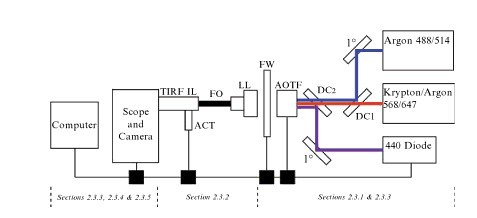
Figure 1 System design. Shown is a generalized diagram of the TIRFM rigs components are noted beneath the figure. All optical components to the right of the Fiber Optic Cable are mounted on a metal breadboard with screws on standard post mounts. Three lasers(boxes on right) are used to provide five usable excitation lines(wavelengths in nm indicated). After reflection on a primary mirror, the argon laser lines are directed to the AOTF via a dichroic mirror(DC1). The krypton-argon lines pass through both DC1 and DC2. After reflection on a primary mirror, the 440-nm diode laser line is directed to the AOTF via DC2. Power at the 440-nm laser head is computer controlled. Control boxes are required to interface with the computer software and are depicted as black boxes. Thin black lines at the bottom of the figure indicate computer connections. The AOTF and excitation filter wheel(FW) are linked to their respective control boxes, which in turn are coupled to the PC workstation and are controlled by MetaMorph acquisition software. The selected line is directed to the laser launch(LL) lens to allow entry into the fiber optic cable. The fiber optic cable is coupled to the TIRF illuminator (TIRFIL).The TIRF angle is controlled through the software via a motorized actuator(ACT).
Excitation light source
Continuous wave lasers provide the illumination source for our TIR FM systems. Typical laser types include gas, diode-pumped, and straight diode; all can be used in combination. The lasers are mounted on an optical breadboard with their polarity and vertical beam heights matched so that they can be combined into a single-mode fiber optic cable, which carries the light to the TIRFM illuminator on the microscope as schematically illustrated in FIG.2
Mixed gas lasers provide an economic means to obtain m ultiple laser lines from a single device. Wavelength selection is accomplished using a sofware-controlled, acousto-optical tunable filter(AOTF). Because of the inadequate blocking power of the AOTF and the fact that gas lasers produce multiple usable(and unusable wavelengths, extraneous excitation light must be blocked from reaching the extremely sensitive cameras used in TIRFM with “cleanup” excitation filters. On our systems, the cleanup filters are placed in a software-controlled filter wheel(FW) on the breadboard after the AOTF to provide versatility and to avoid reflection artifacts that occur if placed in the traditional location within the dichroic beam splitter housing.) (Related products in: Fiber Optic Splitter Box)
Straight diode and diode-pumped solid-state lasers can be up to 10 times smaller in size and are a noise-and heat-free alternative relative to their gas-driven equivalents. Straight diode lasers have a longer life expectancy relative to gas lasers whose tubes must be replaced(usually at a third of the full cost) everu 2-3 years. Straight diodes can be modelated by software control, bypassing the need for an AOTF and thus can be directly linked to a fiber optic cable either at the laser head or, as in the case of our system, mirrored directly into a fiber optic coupler. It is important to note that the square beam shape of a typical diode laser usually results in an unavoidable and significant loss of power throughput at the point of fiber optic coupling. Diode-pumped lasers use a different technology to produce their monochromatic lines and their output must be modelated through an AOTF.

