Tag Archives: CWDM mux demux

Dual-Fiber or Single-Fiber CWDM Mux Demux for Higher Capacity Need?

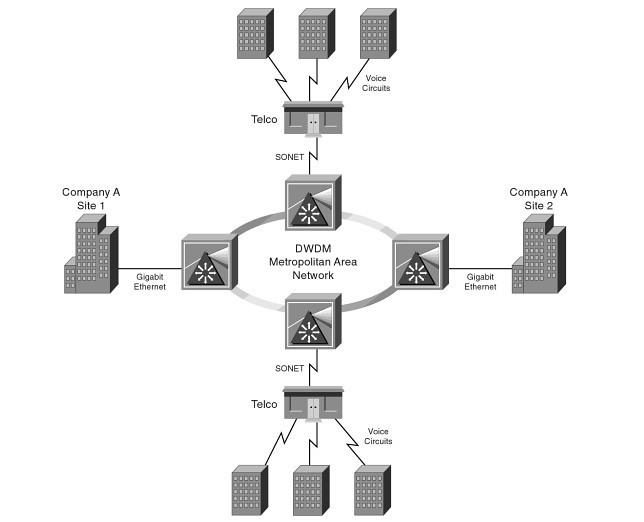
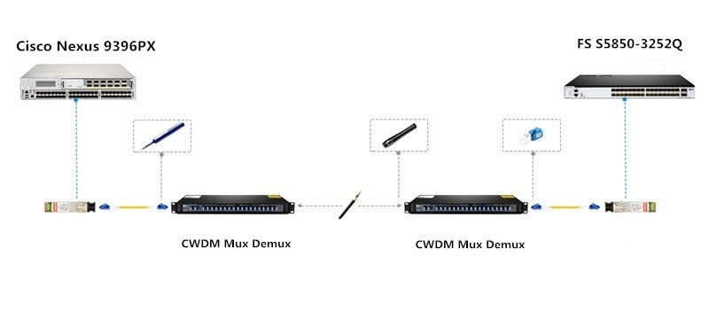
What would you do if your network capacity can not meet your requirement? Will you put more fibers or update your system? In fact, these two methods are not very recommendable. Why? As your fiber cabling infrastructure is limited for adding fibers and high cost is required for upgrading system, these two methods are unworkable or too expensive. Under this condition, using a pair of CWDM Mux Demux to build a CWDM system with higher capacity is highly recommended. The CWDM Mux Demux is regarded as a key component for a CWDM system, as shown below. It can be simply divided into two types, dual-fiber and single-fiber CWDM Mux Demux. To meet the higher capacity need of your system, this post will mainly introduce the basic knowledge of the dual-fiber and single-fiber CWDM Mux Demux and guide you find a suitable fiber optic Mux Demux for building your CWDM system.

CWDM system

Dual-Fiber CWDM Mux Demux

Dual-Fiber CWDM Mux Demux is a passive device multiplexing and demultiplexing the wavelengths for expanding network capacity, which must work in pairs for bidirectional transmission over dual fiber. It enables up to 18 channels for transmitting and receiving 18 kinds of signals, with wavelengths from 1270 nm to 1610 nm. The CWDM transceiver inserted into the fiber optic Mux port should have the same wavelength as that of Mux port to finish the signal transmission. For instance, the two reliable 4 channel CWDM Mux Demux showed below use four wavelengths, 1510 nm, 1530 nm, 1550 nm and 1570 nm, their corresponding CWDM transceivers also features the same wavelengths.

Dual Fiber CWDM Mux Demux

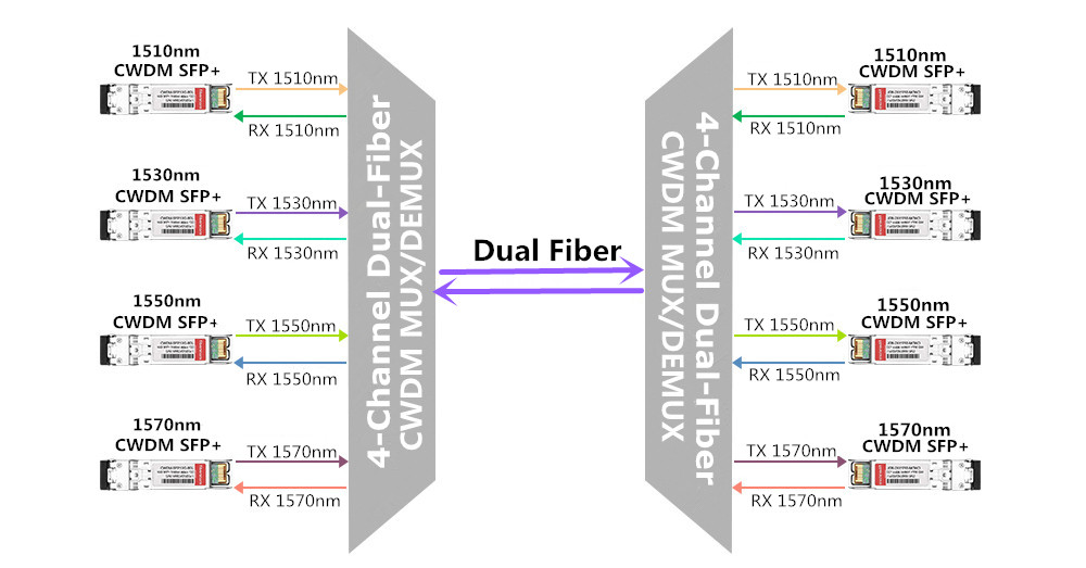
When the connection above works, the left 4 channel dual-fiber CWDM Mux Demux uses 1510 nm, 1530 nm, 1550 nm and 1570 nm for transmitting 4 kinds of signals through the first fiber, while the right 4 channel dual-fiber CWDM Mux Demux features 1510 nm, 1530 nm, 1550 nm and 1570 nm for receiving the signals. On the other hand, the transmission from the right to left use the same wavelengths to carry another 4 signals through the second fiber, finally achieving the bidirectional signal transmission.

Single-Fiber CWDM Mux Demux

Single-fiber CWDM Mux Demux should be also used in pairs. One multiplexes the several signals, transmits them through a single fiber together, while another one at the opposite side of the fiber demultiplexes the integrated signals. Considering that the single-fiber CWDM Mux Demux transmitting and receiving the integrated signals through the same fiber, the wavelengths for RX and TX of the same port on the Single-fiber CWDM Mux Demux should be different. Hence, if the 4 channel single-fiber CWDM Mux Demux is used for CWDM system, 8 wavelengths are required, twice time as that of the dual-fiber one.

Single Fiber CWDM Mux Demux

The working principle of single-fiber CWDM Mux Demux is more complicated, compared to the dual-fiber one. As shown in the figure above, the transmission from the left to right uses 1470 nm, 1510 nm, 1550 nm and 1590 nm to multiplex the signals, transmit them through the single fiber, and using the same four wavelengths to demultiplex the signals, while the opposite transmission carries signals with 1490 nm, 1530 nm, 1570 nm and 1610 nm over the same fiber. As for the wavelength of the transceiver, it should use the same wavelength as TX of the port on the CWDM Mux Demux. For example, when the port of a single-fiber CWDM Mux Demux has 1470 nm for TX and 1490 nm for RX, then a 1470nm CWDM transceiver should be inserted.

Dual-Fiber vs. Single-Fiber CWDM Mux Demux

We always consider whether an item is worth buying according to its performance and cost. In view of the performance, the single-fiber CWDM Mux Demux can carry signals through only one fiber supporting fast speed transmission and saving the fiber resource, while the dual-fiber one requires two fibers for transmission with higher reliability. Besides, using single-fiber CWDM Mux Demux can be easier to install. In view of the cost, the single-fiber CWDM Mux Demux is much more expensive than the dual-fiber. And the simplex fiber cable also costs higher than duplex fiber cable. Thereby, the whole cost for building the single-fiber CWDM system must be much higher. Like the two sides of the same coin, both the dual-fiber and single-fiber CWDM Mux Demux have their own advantages and disadvantages. Which one you should choose just depends on your system needs and your budget for building the CWDM system.

CWDM/DWDM detailed analysis and related solution of the problem

WDM refers to the process of multiplexing optical signals onto a single fiber. Each optical signal is called a lambda. It typically falls into the 1500-1600 nanometer(nm) range. This range is called the WDM window. WDM allows existing networks to scale in bandwidth without requiring additional fiber pairs. This can reduce the recurring cost of operations for metropolitan-and wide-area networks significantly by deferring fiber installation costs. WDM can also enable solutions otherwise impossible to implement in situations where additional fiber installation is not possible.

Wavelength and frequency are bound by the following formula:

                                   C = wavelength * frequency

Where C stands for constant and refers to the speed of light in a vacuum; therefore wavelength cannot be changed without also changing frequency. Because of this, many people confuse WDM with frequency division multiplexing(FDM). Two factors distinguish WDM from FDM. First, FDM generally describes older multiplexing systems that process electrical signals. WDM refers to newer multiplexing systems that process optical signals. Second, each frequency multiplexed in an FDM system represents a single transmission source. Bycontrast, one of the primary WDM applications is the multiplexing of SONET signals, each of which may carry multiple transmissions from multiple sources via TDM. So, WDM combines TDM and FDM techniques to achieve higher bandwidth utilization.

DWDM refers to closely spaced wavelengths; the closer the spacing, the higher the number of channels(bandwidth) per fiber. The International Telecommunication Union(ITU) G.694.1 standard establishes nominal wavelength spacing for DWDM system. Spacing options are specified via a frequency grid ranging from 12.5 gigahertz(GHz), which equates to approximately 0.1 nm, to 100 GHz, which is approximately 0.8 nm. Many DWDM systems historically have supported only 100 GHz spacing(or a multiple of 100 GHz) because of technical challenges associated with closer spacing. Newer DWDM systems support spacing close than 100 GHz. current products typically support transmission rates of 2.5-10 Gbps, and the 40-Gbps market is expected to emerge in 2006.

You can use two methods to transmit through a DWDM system. One of the methods is transparent. This means that the DWDM system will accept any client signal withou special protocol mappings or frame encapsulation techniques. Using this method, a client device is connected to a transparent interface in the DWDM equipment. The DWDM devices accept the client is optical signal and shift the wavelength into the WDM window. The shifted optical signal is then multiplexed with other shifted signals onto a DWDM trunk. Some DWDM-transparent interfaces can accept abroad range of optical signals, whereas others can accept only a narrow range. Some DWDM-transparent interfaces are protocol aware, meaning that the interface understands the client protocol and can monitor the client signal. When using the transparent method, the entire end-to-end DWDM infrastructure is invisible to the client. All link-level operations are conducted end-to-end through the DWDM infrastructure.

Using the second method, a client dvice is connected to a native interface in the DWDM equipment. Fow example, a Fibre Channel switch port is connected to a Fibre Channel port on a line card in a DWDM chassis. The DWDM device terminates the incoming client signal by supporting the client is protocol and actively participating as an end node o n the client is network. For example, a Fibre Channel port in a DWDM device would exchange low-level Fibre channel signals with a Fibre Channel switch and would appear as a brdge potr(B_Port) to the Fibre Channel switch. This non-transparent DWDM transport service has the benefit of localizing some or all link-level operations on each side of the DWDM infrastructure. Non-transparent DWDM service also permits aggregation at the point of ingress into the DWDM network. For examle, eight 1-Gbps Ethernet(GE) ports culd be aggregated onto a single 1–Gbps lambda. The DWDM device must generate a new optical signal for each client signal that it terminates. The DWDM device must generate a new optical signal for each client signal that it terminates. The newly generated optical signals are in the WDM widow and are multiplexed onto a DWDM trunk. Non-transparent DWDM service also supports monitoring of the client protocol signals.


30


To the extent that client devices are unaware of the CWDM system, and all link-level operations are conducted end-to-end, transparent CWDM service is essentially the same as transparent DWDM service. Transparent CWDM mux/demux equipment is typically passive(not powered). Passive devices cannot generate or repeat optical signals. Additionally, 10As operate in a small wavelength range that overlaps only three CWDM signals. Some CWDM signals are unaffected by 10As, so each CWDM span must terminate at a distance determined by the unamplified signals. Therefore, no benefit is realized by amplifying any of the CWDMsignals. This means that all optical signal loss introduced by CWDM mux demux equipment, splices, connectors, and the fiber must be subtracted from the launch power of the colored GBIC/SFP installed in the client. Thus, the client GBIC/SFP determines the theoretical maximum distance that can be traversed. Colored GBICs/SFPs typically are limited to 80 km in a point-to-point configuration, but may reach up to 120 km under ideal conditions. Signal monitoring typically is not implemented in CWDM devices.