Tag Archives: CWDM technology

CWDM/DWDM technical overview

CWDM is an optical technology for transmitting up to 16 channels, each in a separate wavelength or color, over the same fiber strand. The CWDM solutions help enable enter-prises and service providers to increase the bandwidth of an existing Gigabit Ethernet optical infrastructure without adding new fiber strands. Unlike DWDM, which can transmit up to 160 channels on the same fiber by tightly packing them, CWDM technology relies on wider spacing between channels. this design makes CWDM a relatively inexpensive technology for transmitting multiple gigabit-per-second signals on a single fiber strand as compared with DWDM because it can support less-sophisticated, and therefore cheaper, transceiver designs. In the point-to-point configuration shown in Figure 1-1, two rndpoints are directly connected through a fiber link. The ITU has standardized a 20-nm channel-spacing grid for use with CWDM, using the wavelengths between 1310 nm and 1610 nm. Most CWDM systems support eight channels in the 1470-to 1610-nm range. The Fiberstore CWDM Gigabit Interface Converter small form-factor pluggable(SFP) solution allows organizations to add or drop as many as eight channels (Gigabit Ethernet or Fibre Channel) into a pair of single-mode (SM) fiber strands. As a result, the need for additional fiber is minimized. You can create redundant point-to-point links by adding or dropping redundant channels into a second pair of SM fiber strands.
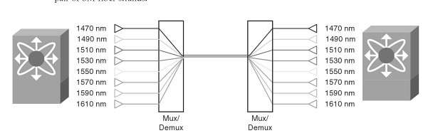
9     Figure 1-1


CWDM Technical Overview

CWDM Multiplexer is achieved thruogh special passive (nonpowered) glass devices known as filters. The filters act as prisms, directing lights from many incoming and outgoing fibers (client ports) to a common transmit and receive trunk pots. Optical multiplexing in a ring with CWDM networks is supported with optical add/drop multiplexers (OADM). OADMs can drop off one or more CWDM wavelengths at a specific location and replace that signal with one or more diferent outbound signals. The Fiberstore CWDM GBIC/SFP solution has two main components: a set of eight different pluggable transceivers (Fiberstore CWDM GBICs and CWDM SFP), and a set of different Fiberstore CWDM passive multiplexers/demultiplexers or OADMs. Both the transceivers and the passive multiplexers are compliant with the CWDM grid defined in the standards. CWDM can be used by enterprises on leased dark fiber to increase capacity (for example, from 1 Gbps to 8 Gbps or 16 Gbps) over metro-area distances. One problem with CWDM is that the wavelengths are not compatible with erbium-doped fiber amplifier (EDFA) technology, which amplifies all light signals within their frequency range. CWDM supports up to a 30 -dB power budget on an SM fiber. This restricts the distances over which CWDM may be used. CWDM supports distances of approximately 60 miles (100km) in a point-to-point topology and about 25 miles (40 km) in a ring topology. in some areas, service providers use CWDM to provide lambda or wavelength services. A lambda service is where a provider manages equipment and multiplexes customer traffic onto one or more wavelengths for a high-speed connection, typically bet ween two or more points.

DWDM Technical Overview

DWDM is a core technology in an optical transport network. The concepts of DWDM are similar to those for CWDM. However, DWDM spaces the wavelengths more tightly, yielding up to 160 channels. The tighter channel spacing in DWDM requires more sophisticated, precise,and therefore more expensive transceiver designs. In a service provider is backbone network, the majority of embedded fiber is standard SM fiber with high dispersion in the 1550-nm wubdiw, DWDM supports 32 or more channels in the narrow band around 1550 nm at 100-GHz spacing, or about 0.8 nm, as illustrated in Figure1-2. Because of the EDFA compatibility of the wavelenths used, DWDM is also available over much longer distances than CWDM and supports metropolitan-area network (MAN) and WAN applications. In practice, signals can travel for up to 75 miles (120 km) between amplifiers if fiber with EDFA is used. At distances of 375 miles (600 km) to 600 miles (1000 km), the signal must be regenerated.
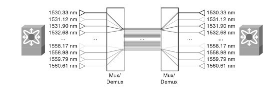
8

Figure 1-2

DWDM can be used as a high-speed enterprise WAN connectivity service. Typical DWDM uses include connectivity between sites and data centers for example 1-, 2-, or 4- Gbps Fiber channel; IBMfiber connectivity (FICON) and Enterprise System Connection(ESCON); and Gigabit and 10 Gigabit Ethernet. Protection options include client-side safeguards using rerouting, an optical splitter that allows the signal to go both ways around a ring or line-card-based protection that detects boss of signal and wraps.

Continue reading

The principle of optical fiber connector and classification

In optical fiber communication (transmission) link, in order to achieve the different modules.The needs of the flexible connection between devices and systems, there must be a able to removable between optical fiber and optical fiber (activities) of the connection device, can make the light path according to the required transmission channel, with the purpose of the implementation and complete reservation or expectations and requirements, can realize the function of the device is called a connector.Optical fiber connector is the fiber of two surface precision docking, so that the optical output of light energy to maximize the coupling to the receiving optical fiber, and optical link due to the intervention and to minimize the effects on the system, it is the basic requirement of optical fiber connector.To a certain extent, optical fiber connector also affects the reliability and the performance of optical transmission system.

A.Is the main optical fiber connection

1. The fixed connection.Mainly used for permanent connection between optical fiber in optical fiber cable line, with welding, also have use bonding and mechanical connection.Is characterized by low coupling loss, high mechanical strength.Equipment need welding machine, probably thousands of dollars.
2. Active connection.Is mainly used in optical fiber transmission system equipment and instrument connections between, mainly through the optical coupler plug connection.Is characterized by flexible joint is better, exchange connection is convenient, large loss and reflection is the lack of this connection.Now the insertion loss is already very good, dozens of RMB is ok, you can directly buy finished product, if you want to bulk, also need to face polishing grinding equipment, that is too expensive, suggested that direct buy jump line.
3. A temporary connection.Measure the tail fiber and measured coupling between optical fiber connection, connected by this method.Characteristic is convenient and flexible, low cost, low requirements for loss, temporary measure when use this way to connect more.Also can use welding machine or V groove with glue.

B. To optical fiber connection request

1. The requirements for fixed connection Optical fiber fixed connection cable line is a key technology.Demand for fixed connection has the following several aspects: coupling loss is small, good consistency;Coupling loss stability is better, general difference in temperature range should not have the generation of additional loss;Has enough mechanical strength and service life;Operation should be simple, easy to construction work;Joint to small volume, easy to place and protection;Low cost, material is easy to be processed.
2. The requirement of active connection For removable optical fiber connection, are now using mechanical connector.The requirement basically has the following several aspects: connection loss, single-mode fiber loss is less than 0.5 dB;Should have good repeatability and interchangeability.After repeatedly plug and interchangeable parts, there is still a good consistency;Has good stability, fittings insertion loss stability after fastening, not affected by temperature change;Smaller volume, weight light;Have certain strength;The price is suitable.
3. Optical fiber temporary connection to temporary connection request, also can use the welding machine welding.Require low loss as much as possible, in connection with V groove and capillary, must add liquid ratio, otherwise unable to eliminate the Fresnel reflection.3. Optical fiber connection loss factor

C.Optical fiber connection loss factor

After the fiber connection, light through joint parts will produce certain loss, known as optical fiber connecting the transmission loss, the splicing loss.The main analysis of single-mode fiber coupling loss factor.
1. The intrinsic factors on the connection is most affected by single mode optical fiber mode field diameter.When 20% of mode field diameter mismatch, will produce 0.2 dB over the loss.As far as possible the use of optical fiber mode field diameter smaller, to reduce the loss of connection has the vital significance.
2. The external factors outside the main factors of single-mode optical fiber connection loss for the axis displacement and axial tilt.For mechanical connection with vertical to the weld and the fiber core deformation and other factors.
(1) axis misalignment.When the dislocation at 1.2 microns, cause the loss of 0.5 dB, connected to the positioning accuracy, can effectively control the influence of the axial displacement.
(2) the axial tilt.When the tilt reaches 1 °, will cause a loss of 0.2 dB.Selects the high quality fiber cutting knife, can improve the axial tilt caused by wear and tear.
(3) the fiber core deformation.When the amount of current, advancing the automatic welding machine, discharge current, time set reasonable, such as fiber core deformation caused by the wastage can do below 0.02 dB.

D. Optical fiber connection method and comparison

1. The welding machine welding This method is mainly used for optical fiber joint connection, is currently used more in automatic welding machine for welding, welding machine points single core and multicore welding machine two kinds.Before formally succeeded, welding machine, the experiments of various parameters to determine the alignment precision of welding machine, discharge size, the quantity of various parameters, such as, to adapt it to the concrete in the specific working conditions of the fiber, the loss of control within a set of indicators.Succeeded completed, should be timely optical time-domain reflectometer to determine the loss, after the loss conform to the requirements of the indicators, before being reinforcing process, until the complete connection.
2. Mechanical connection By far the most common connection characteristics of three types of mechanical connector is as follows: process FO type connector.This kind of optical fiber connector is standard connection form of single core optical fiber.Most of the current product end face grinding to turn it into a ball, the convergence of the beams using optics refraction principle, reduce the loss of the connection.This kind of optical fiber connector multi-purpose on optical fiber distribution frame and test instrument, for transfer.NTT multicore fiber optic connectors.This kind of optical fiber connector can be connected a 12 optical fibers, has a large capacity, simple manufacturing process, and in place of low loss, therefore, in less demanding users to connect optical fiber has been widely used.This method used in optical fiber short distance relay, relay and users, the effect is better.Wire connector.With the development of technology, wiring son can do 0.1 dB below the average in loss and 50% of the splicing loss can be below 0.05 dB, adaptability to the environment temperature and humidity is relatively good.Due to this kind of connection method does not require expensive welding machine, and a single core and multicore specifications, convenient use and expects its prospect of application is more and more wide, make the connection of the fiber as convenient as cable.In the development of optical fiber communication technology is critical.Simplify the connection technology, improve the quality of connection, to expand fiber applications will play a positive role in promoting.

Related articles:CWDM DWDM,CWDM technology,CWDM Add Drop Multiplexer,WDM networks