Tag Archives: MTP cassette

MTP Solutions for High-Density Needs

With the ever-increasing demands for high-density backbone cabling. MTP solutions have enjoyed widespread popularity. In this post, we will have an exploration of two MTP solutions: MTP cable and MTP cassette. For those who are unfamiliar with this term, it’s necessary for us to get started from its basics.

Background Information on MTP

In this part, you are required to acquire three terms: MTP, MPO, and polarity.

MPO

MPO stands for “multi-fiber push on” connector. Usually, it refers to a type of a multiple fiber core connector, defined by IEC-61754-7 (common standard) and the U.S. TIA-604-5 Standard.

MTP

MTP is the short for “multi-fiber termination push-on” connector, which is the latest generation of MPO connector developed by US Conec. Fully compliant with the MPO standards, the multi-fiber termination push-on connector is considered as MPO fiber connector. For multi-fiber termination push-on or multi-fiber push on connector, they can both accommodate 8 to 24 fibers, which are the perfect choices for the 40G/100G network. Multi-fiber termination push-on or multi-fiber push on connector is available in a female version (without pins), or a male version (with pins) as shown in figure 1. The pins ensure the exact alignment of the fronts of the connectors, which protects the interfaces of the connectors from being offset.

MTP Connectors

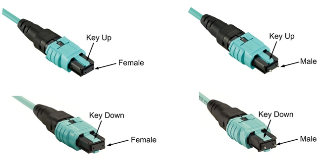
Figure 1: MTP Connectors

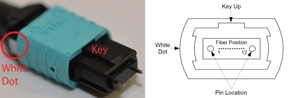
Also, there are guide grooves (keys) on the top side of the factory terminated multi-fiber termination push-on connectors, which ensure that the adapter holds the connector with the correct ends aligned with each other. According to the key, the multi-fiber termination push-on connector comes with two types. One is “key-up to key-down”, which means the key is up on the one side and down on the other. The two connectors are connected turned 180°in relation to each other. The other one is “key-up to key-up”, which means both keys are up. The two connectors are connected while in the same position in relation to each other.

MTP Connector Structure

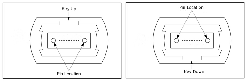
Figure 2:  Multi-fiber Termination Push-on Connector Structure

Polarity

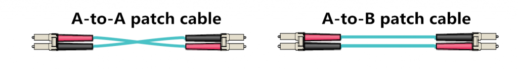
In any installation, it is important to ensure that the optical transmitter at one end is connected to the optical receiver at the other. This matching of the transmitting signal (Tx) to the receiving equipment (Rx) at both ends of the fiber optic link is referred to as polarity.

MTP Solutions

For multi-fiber termination push-on solutions, there are two frequently used applications: MTP cable and multi-fiber termination push-on cassettes. They are the best choices for providing a simple, cost-effective, and structured cabling system.

MTP Solutions

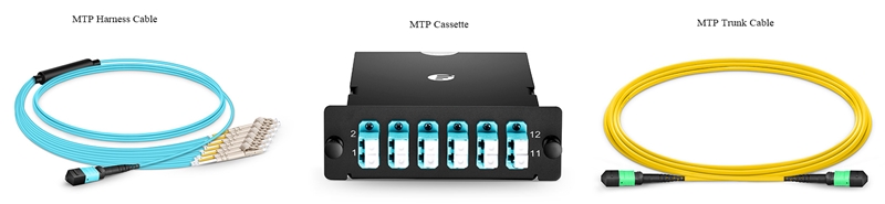
Figure 3: MTP Solutions

Cables

Multi-fiber termination push-on cables usually consist of the multi-fiber termination push-on connectors and the fiber optic cables. Sometimes, the LC connectors are used, which we will expound in the following part. As for fiber cables, they are typically used in OS2, OM3 or OM4. With different applications, the multi-fiber termination push-on cable can be classified into multi-fiber termination push-on trunk cable and multi-fiber termination push-on harness cable.

Trunk Cable

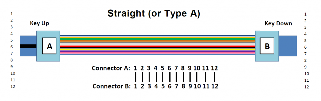
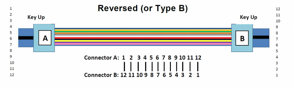
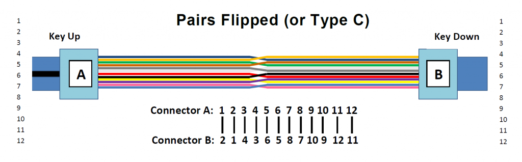
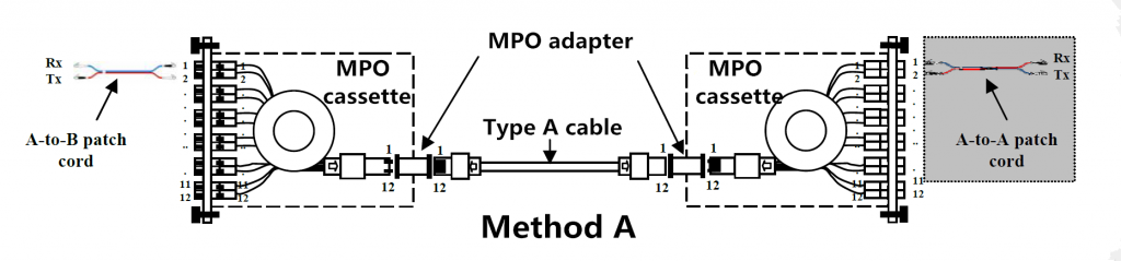
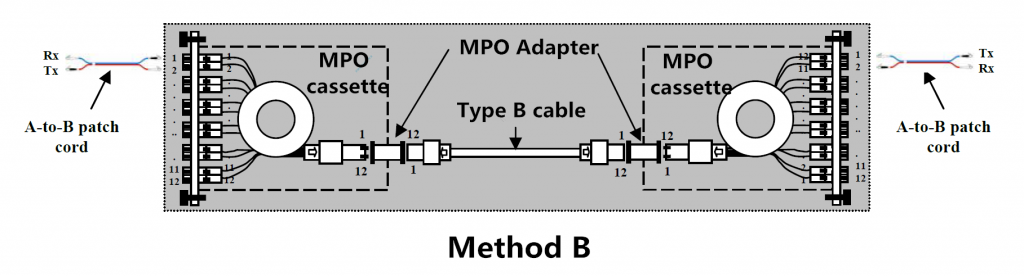
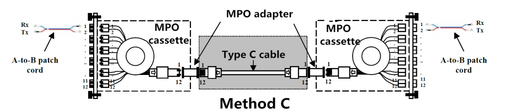
Serving as a permanent link, the trunk cable is designed to connect multi-fiber termination push-on or multi-fiber push on modules to each other. It’s available in 12, 24, 48 and 72 fibers. For the ends, the cable is commonly found to be terminated with 12-fiber or 24-fiber multi-fiber termination push-on or multi-fiber push on connectors. When it comes with the polarity of the patch cord, there are three different types (type A, B, and C), which is defined in the TIA standard. In the following figures, the three different connectivity methods for 12-fiber and 24-fiber MTP/MPO trunk cable are showed respectively.

12-Fiber MTP Trunk Cable

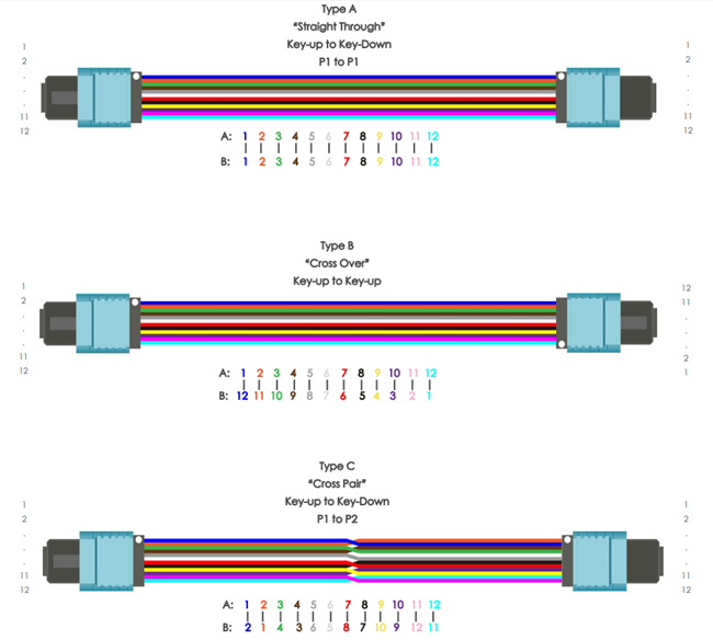
Figure 4: 12-Fiber Multi-fiber Termination Push-on Trunk Cable

24-Fiber MTP Trunk Cable

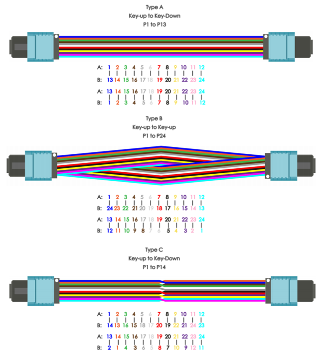
Figure 5: 24-Fiber Multi-fiber Termination Push-on Trunk Cable

Harness Cable

Multi-fiber termination push-on harness cable is used to provide a transition from multifiber cables to individual fibers or duplex connectors. For instance, 8 fibers 12 strands MTP-LC breakout cable has eight LC fiber connectors and a multi-fiber termination push-on connector. According to data of FS.COM, the 8-fiber and 24-fiber MTP to LC breakout cables are the best-selling multi-fiber termination push-on connector harness cables. For the polarity, the 8-fiber multi-fiber termination push-on connector breakout patch cord has two types (Type A and Type B); while the 24-fiber harness cable has three types (Type A, Type B, and Type C). For details, please refer to the following figures.

12-Fiber MTP Harness Cable

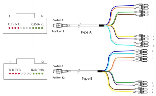
Figure 6: 12-Fiber Multi-fiber Termination Push-on Harness Cable

24-Fiber MTP Harness Cable

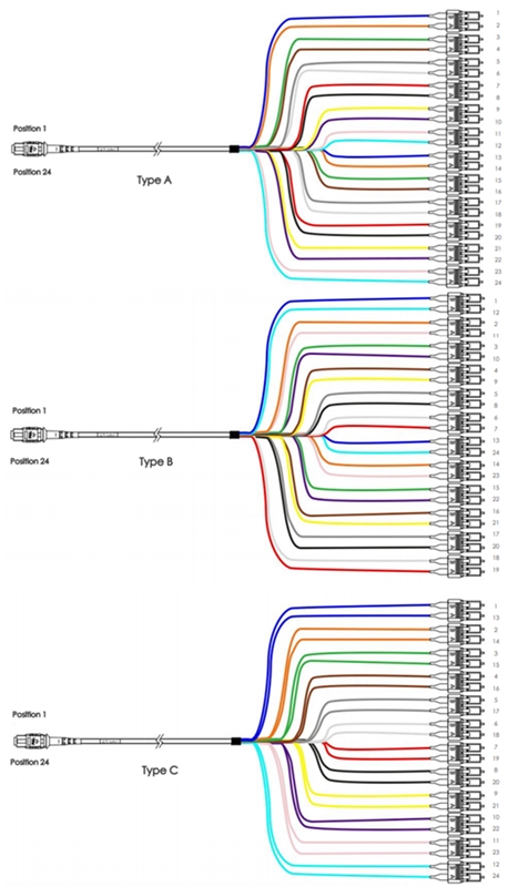
Figure 7: 24-Fiber Multi-fiber Termination Push-on Harness Cable

 Cassette

MTP-cassette is a kind of pre-terminated cassette module. It enables the “transition” from ribbon cables terminated with multi-fiber termination push-on connector connectors to the LC or SC interface on the transceiver terminal equipment. Conventionally, the multi-fiber termination push-on connector cassette is loaded with 8, 12 or 24 fibers and have LC or SC adapters on the front side and multi-fiber termination push-on connector at the rear. Nowadays, the three most widely used cassettes are MTP-8, MTP-12, and MTP-24 cassettes, or also known as Base-8, Base-12, and Base-24 multi-fiber termination push-on cassettes. For MTP-8 cassette, it is only available in Type A. While multi-fiber termination push-on-12 and multi-fiber termination push-on-24 cassettes both come with Type A and Type AF. For their polarity details, please refer to the following figures.

MTP-8 Cassette

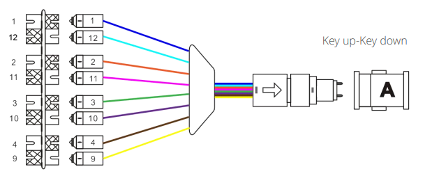
Figure 8: Multi-fiber Termination Push-on-8 Cassette

MTP-12 Cassette

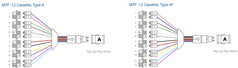
Figure 9:  Multi-fiber Termination Push-on-12 Cassette

MTP-24 Cassette

Figure 10:  Multi-fiber Termination Push-on-24 Cassette

Summary

In this post, we make an overview of MTP, including what the multi-fiber termination push-on and multi-fiber push on, and what their the polarities are. Then we share three types of multi-fiber termination push-on solutions for high-density networking: MTP trunk cable, MTP harness cable, and MTP cassette.

How to Make Full Use of Fiber Optic Enclosure

Fiber optic enclosure is now being widely used in data center to provide high density and safe cabling environment in data centers or server room. With the cabling density of the data center becoming higher and higher, fiber optic enclosures are asked to provide more functions and more flexible cabling environment for various applications. A previous blog post of mine—Which Fiber Patch Enclosure Fits Your Data Center Application—has introduced various types of the fiber optic enclosures that are commonly used. Selecting the right fiber optic enclosure is necessary. The right use of fiber optic enclosure is also very important. This post will offer details about how to make full use of fiber optic enclosure in data center for flexible and manageable cabling environment.

Important Accessories for Flexible Cabling

When you buy an empty fiber optic enclosure, no matter it is a slide-out one or fixed one, there are many accessories like screws and grommet. The front panel of the fiber optic enclosure might not be loaded. There are several accessories that can directly determine the way you use a fiber optic enclosure. Taking the example of a 1U slide-out fiber enclosure as an example (shown in the following picture), the following will introduce three popular ways to use fiber enclosures with different accessories. The accessories required are separate, splice tray & FAP (fiber adapter panel), slack spool & FAP and HD MTP cassette.

1U fiber optic enclosure

Fiber Optic Enclosure for Fiber Splicing Joints

Accessories required for fiber splicing joints in this fiber optic enclosure are splice tray and FAPs. The splicing tray can be installed on the slide-out drawer of the fiber enclosure for fiber splicing joints storing and cabling. An additional multi-fiber pigtail is also required to be fusion spliced with the input fiber optic cable. Then this fiber pigtail will be connected to the FAPs installed on the front panel. The following picture shows the loaded and connected fiber optic enclosure for fiber optic splicing joints.

fiber optic enclosure for splicing joints

Fiber Optic Enclosure for Patch Cord Connections

Patch cording connection fiber optic enclosure is very common. Just install two slack spools and four fiber adapter panels on this fiber enclosure. It could provide an easy-to-manage environment for fiber patch cables. The two spools installed in the slide-out drawer can help to manage these fiber patch cords The following picture shows a breakout fiber patch cable installed in the fiber optic enclosure and being well organized by the spools.

fiber optic enclosure with spools

Fiber Optic Enclosure for MTP Interface to LC Interface Transferring

With the deployment of the 40G/100G network, the transferring between 40G/100G MTP interfaces and 10G LC interfaces is requires. To minimize the installation time and ensure the connection quality, MTP cassettes are widely used. This 1U rack mount fiber optic enclosure can hold up to 4 HD MTP cassettes. The following picture shows the loaded fiber optic enclosure with four HD MTP cassettes which are connected by several input MTP trunk cables.

fiber enclosure with MTP cassettes

Summary

Using different accessories fiber optic enclosures can meet diverse cabling environment requirements. The above mentioned three methods are the most commonly used ones. Kindly visit FS.COM or contact sales@fs.com for more details about fiber optic enclosure, if you are interested.

Understanding MPO Cable and Polarity

MPO/MTP technology, which is of high density, flexibility and reliability with scalable, upgradeable properties, is one of the contributors that lead the migration to 40/100GbE. However, the network designers face another challenge which is how to assure the proper polarity of these array connections using multi-fiber MPO/MTP components from end-to-end. Maintain the correct polarity across a fiber network ensures that a transmit signal from any type of active equipment will be directed to receive port of a second piece of active equipment – and vice versa. To ensure the MPO cable work with correct polarity, the TIA 568 standard provided three methods, which will be introduced in this article.

MPO Connector

To understand the polarity in 40/100 GbE Transmission, the key of MPO technology—MPO cable connector should be first introduced. MPO connector usually has 12 fibers. 24 fibers, 36 fibers and 72 fibers are also available. Each MTP connector has a key on one of the flat side added by the body. When the key sits on the bottom, this is called key down. When the key sits on top, this is referred to as the key up position. In this orientation, each of the fiber holes in the connector is numbered in sequence from left to right and is referred as fiber position, or P1, P2, etc. A white dot is additionally marked on one side of the connector to denote where the position 1 is. (shown in the following picture) The orientation of this key also determines the MPO cable polarity.

MPO cable connector

Three Cables for Three Polarization Methods

The three methods for proper polarity defined by TIA 568 standard are named as Method A, Method B and Method C. To match these standards, three type of MPO truck cables with different structures named Type A, Type B and Type C are being used for the three different connectivity methods respectively. In this part, the three different cables will be introduced firstly and then the three connectivity methods.

MPO Trunk Cable Type A: Type A cable also known as straight cable, is a straight through cable with a key up MPO connector on one end and a key down MPO connector on the opposite end. This makes the fibers at each end of the cable have the same fiber position. For example, the fiber located at position 1 (P1) of the connector on one side will arrive at P1 at the other connector. The fiber sequence of a 12 fiber MPO Type A cable is showed as the following:

Type A MTP Cable

MPO Trunk Cable Type B: Type B cable (reversed cable) uses key up connector on both ends of the cable. This type of array mating results in an inversion, which means the fiber positions are reversed at each end. The fiber at P1 at one end is mated with fiber at P12 at the opposing end. The following picture shows the fiber sequences of a 12 fiber Type B cable.

Type B cable

MPO Trunk Cable Type C: Type C cable (pairs flipped cable) looks like Type A cable with one key up connector and one key down connector on each side. However, in Type C each adjacent pair of fibers at one end are flipped at the other end. For example, the fiber at position 1 on one end is shifted to position 2 at the other end of the cable. The fiber at position 2 at one end is shifted to position 1 at the opposite end etc. The fiber sequence of Type C cable is demonstrated in the following picture.

Type C Cable

Three Connectivity Methods

Different polarity methods use different types of MTP trunk cables. However, all the methods should use duplex patch cable to achieve the fiber circuit. The TIA standard also defines two types of duplex fiber patch cables terminated with LC or SC connectors to complete an end-to-end fiber duplex connection: A-to-A type patch cable—a cross version and A-to-B type patch cable—a straight-through version.

Duplex patch cable

The following part illustrates how the components in MPO system are used together to maintain the proper polarization connectivity, which are defined by TIA standards.

Method A: the connectivity Method A is shown in the following picture. A type-A trunk cable connects a MPO module on each side of the link. In Method A, two types of patch cords are used to correct the polarity. The patch cable on the left is standard duplex A-to-B type, while on the right a duplex A-to-A type patch cable is employed.

Method A

Method B: in Connectivity Method B, a Type B truck cable is used to connect the two modules on each side of the link. As mentioned, the fiber positions of Type B cable are reversed at each end. Therefore standard A-to-B type duplex patch cables are used on both sided.

Method B

Method C: the pair-reversed trunk cable is used in Method C connectivity to connect the MPO modules one each side of the link. Patch cords at both ends are the standard duplex A-to-B type.

Method C

Conclusion

Network designer using MPO/MTP components to satisfy the increasing requirement for higher transmission speed, during which one of the big problems—polarity, can be solved by selecting the right types of MPO cables, MPO connectors, MPO cassette and patch cables. The three different polarization methods can be applied according to the satisfy requirements in different situations. For more information about polarity in MPO systems and 40/100GbE transmission polarity solutions, please visit Fiberstore tutorial at “Polarity and MPO Technology in 40/100GbE Transmission“.

Related articles: Understanding Polarity in MPO System

                             Introduction to MTP Connector and MPO Connector