Category Archives: 400G Network

Basics about 400G DAC and 400G AOC

Data centers, enterprises, and high-performance computing environments require flexible and well-defined 50G, 100G, 200G, and 400G direct attach cables for interconnection within a rack or between adjacent racks. With the development of 400G technology, 400G direct attach cables for short-distance DCI (Data Center Interconnect) have been mass-produced and put into market, which includes 400G DAC and 400G AOC.

Main Types of 400G DAC & AOC in the Market

Either 400G DAC or 400G AOC comes with two main form factors: QSFP-DD and OSFP, both of which can carry 8x50Gb/s PAM4 electrical lanes. Besides, there are also 400G breakout DAC/AOCs, with one 400G connector at one end, and several same connectors whose total rate is 400G at the other end. The table below shows the main types of 400G DAC /AOC and the 400G breakout DAC/AOCs in the market.

CatagoryNameProduct DescriptionReachApplication
400G QSFP-DD DACQSFP-DD to QSFP-DD DACwith each 400G QSFP-DD using 8x 50G PAM4 electrical lanesno more than 3m400G network direct connection
400G QSFP-DD Breakout DACQSFP-DD to 2x 200G QSFP56 DACwith each 200G QSFP56 using 4x 50G PAM4 electrical lanesno more than 3m400G to 200G network connection
QSFP-DD to 4x 100G QSFPs DACwith each 100G QSFPs using 2x 50G PAM4 electrical lanesno more than 3m400G to 100G network connection
QSFP-DD to 8x 50G SFP56 DACwith each 50G SFP56 using 1x 50G PAM4 electrical laneno more than 3m400G to 50G network connection
400G QSFP-DD AOCQSFP-DD to QSFP-DD AOCwith each 400G QSFP-DD using 8x 50G PAM4 electrical lanes70m (OM3) or 100m (OM4)400G network direct connection
400G QSFP-DD Breakout AOCQSFP-DD to 2x 200G QSFP56 AOCwith each 200G QSFP56 using 4X 50G PAM4 electrical lane70m (OM3) or 100m (OM4)400G to 200G network connection
QSFP-DD to 8x 50G SFP56 AOCwith each 50G SFP56 using 1x 50G PAM4 electrical lane70m (OM3) or 100m (OM4)400G to 50G network connection
400G OSFP DACOSFP to OSFP DACwith each 400G OSFP using 8x 50G PAM4 electrical lanesno more than 3m400G network direct connection
400G OSFP Breakout DACOSFP to 2x 200G QSFP56 DACwith each 200G QSFP56 using 4x 50G PAM4 electrical lanesno more than 3m400G to 200G network connection
OSFP to 4x100G QSFPs DACwith each 100G QSFPs using 2x 50G PAM4 electrical lanesno more than 3m400G to 100G network connection
OSFP to 8x 50G SFP56 DACwith each 50G SFP56 using 1x 50G PAM4 electrical laneno more than 3m400G to 50G network connection
400G OSFP AOCOSFP to OSFP AOCwith each 400G OSFP using 8x 50G PAM4 electrical lanes70m (OM3) or 100m (OM4)400G network direct connection

Differences Between 400G DAC and 400G AOC

According to the table, we know that the main differences between 400G DAC and 400G AOC are transmission distance and the available types on the market. At present, 400G DAC can provide more breakout cables and better satisfy your different connection requirements. Apart from that, 400G DAC and AOC differ from each other in the following aspects.

  • Weight and volume – With fiber optic cable as transmission media, 400G AOC has about half the volume and only a quarter the weight of 400G copper DAC. Also, its cable bending radius is smaller than 400G DAC.
  • Interference-resistance – Since 400G AOC with fiber optic cable doesn’t conduct electrical currents, it is resistant to interference from electromagnetic, lightning, or radio signals during data transmission. While 400G DAC with copper cable is vulnerable to power lines, lightning, and signal-scrambling.
  • Price – On today’s 400GbE cable market, the price of the 400G AOC is often higher than that of 400G DAC, of course, with the same level. If both of them can meet your needs, you can choose a 400G DAC to save costs.

Further Consideration about 400G DAC and 400G AOC

Both 400G DAC and AOC are cost-effective solutions for short-distance transmission. When it comes to the transmission over 100m, 400G optical transceivers combined with the matched fiber optic cables are a suitable solution. In today’s market, 400G QSFP-DD/OSFP transceivers are continuously being pushed to the market and gradually realize mass production. So, what are 400G QSFP-DD/OSFP transceiver types and what fiber optic cables could be used with these 400G optical modules? Continue reading to find the answers in the two articles: 400G OSFP Transceiver Types Overview400G QSFP-DD Transceiver Types Overview.

FAQ about 400G DAC/AOC

Q: Why does 400G DAC/AOC adopt PAM4 modulation?

A: PAM4 is a more efficient modulation technology that can effectively improve the bandwidth utilization efficiency. With same Baud rate, PAM4 signal can transmit twice faster than the traditional NRZ signal. Also, the transmission costs are greatly reduced.

Q: What’s the key technology of 400G DAC/AOC?

A: The core technologies of 400G DAC/AOC are PAM4 and DSP. Since PAM4 is more sensitive to noise than NRZ especially in 400G AOC, DSP is introduced to make up for the disadvantage of PAM4. As a high-speed digital processing chip, DSP not only owns the function of recovering signal provided by the traditional CDR but also can make dispersion compensation and remove noise, nonlinear disturbance as well as other interferences.

FS 400G DAC Cables
Article Source

https://community.fs.com/blog/400g-direct-attach-cables-dac-and-aoc-overview.html

Related Articles

https://community.fs.com/blog/400g-transceiver-dac-or-aoc-how-to-choose.html

https://community.fs.com/news/fs-400g-cabling-solutions-dac-aoc-and-fiber-cabling.html

ROADM for 400G WDM Transmission

As global optical networks advance, there is an increasing necessity for new technologies such as 400G that meet the demands of network operators. Video streaming, surging data volumes, 5G network, remote working, and ever-growing business necessities create extreme bandwidth demands.

Network operators and data centers are also embracing WDM transmission to boost data transfer speed, increase bandwidth and enhance a better user experience. And to solve some of the common 400G WDM transmission problems, such as reduced transmission reach, ROADMs are being deployed. Below, we have discussed more about ROADM for 400G WDM transmission.

Reconfigurable Optical Add-drop Multiplexer (ROADM) Technology

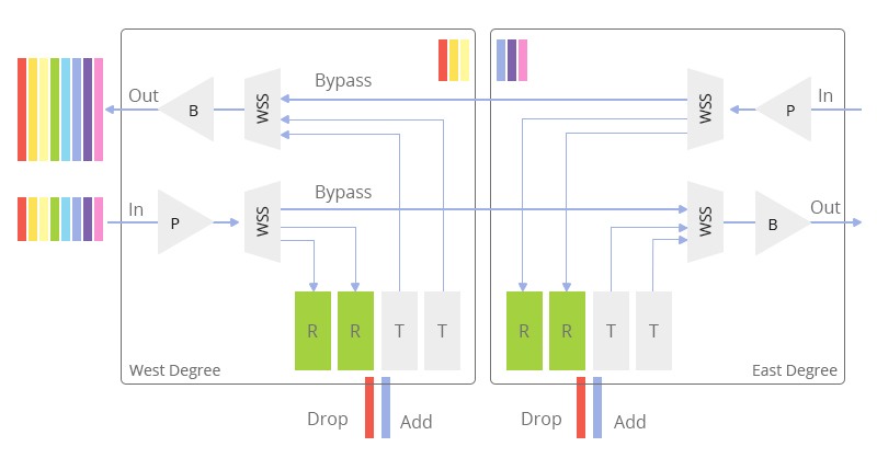
ROADM is a device with access to all wavelengths on a fiber line. Introduced in the early 2000s, ROADM allows for remote configuration/reconfiguration of A-Z lightpaths. Its networking standard makes it possible to block, add, redirect or pass visible light beams and modulated infrared (IR) in the fiber-optic network depending on the particular wavelength.

ROADMs are employed in systems that utilize wavelength division multiplexing (WDM). It also supports more than two directions at sites for optical mesh-based networking. Unlike its predecessor, the OADM, ROADM can adjust the add/drop vs. pass-through configuration whenever traffic patterns change.

As a result, the operations are simplified by automating the connections through an intermediate site. This implies that it’s unnecessary to deploy technicians to perform manual patches in response to a new wavelength or alter a wavelength’s path. The results are optimized network traffic where bandwidth demands are met without incurring extra costs.

ROADM

Overview of Open ROADM

Open ROADM is a 400G pluggable solution that champions cross-vendor interoperability for optical equipment, including ROADMs, transponders, and pluggable optics. This solution defines some optical interoperability requirements for ROADM and comprises hardware devices that manage and routes traffic over the fiber optic lines.

Initially, Open ROADM was designed to address the rise in data traffic on wireless networks experienced between 2007 and 2015. The major components of Open ROADM – ROADM switch, pluggable optics, and transponder – are controllable via an open standards-based API accessible through an SDN Controller.

One of the main objectives of Open ROADM is to ensure network operators and vendors devise a universal approach to designing networks that are flexible, scalable, and cost-effective. It also offers a standard model to streamline the management of multi-vendor optical network infrastructure.

400G and WDM Transmission

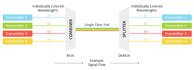
WDM transmission is a multiplexing technique of several optical carrier signals through a single optical fiber channel by varying the wavelength of the laser lights. This technology allows different data streams to travel in both directions over a fiber network, increasing bandwidth and reducing the number of fibers used in the primary network or transmission line.

With 400G technology seeing widespread adoption in various industries, there’s a need for optical fiber networking systems to adapt and support the increasing data speeds and capacity. WDM transmission technique offers this convenience and is considered a technology of choice for transmitting larger amounts of data across networks/sites. WDM-based networks can also hold various data traffic at different speeds over an optical channel, allowing for increased flexibility.

400G WDM still faces a number of challenges. For instance, the high symbol rate stresses the DAC/ADC in terms of bandwidth, while the high-order quadrature amplitude modulation (QAM) stresses the DAC/ADC in terms of its ENOB (effective number of bits.)

As far as transmission performance is concerned, the high-order QAM requires more optical signal-to-noise ratio (OSNR) at the receiver side, which reduces the transmission reach. Additionally, it’s more sensitive to the accumulation of linear and non-linear phase noise. Most of these constraints can be solved with the use of ROADM architectures. We’ve discussed more below.

WDM Transmission

Open ROADM MSA and the ROADM Architecture for 400G WDM

The Open ROADM MSA defines some interoperability specifications for ROADM switches, pluggable optics, and transponders. Most ROADMs in the market are proprietary devices built by specific suppliers making interoperability a bit challenging. The Open ROADM MSA, therefore, seeks to provide the technical foundation to deploy networks with increased flexibility.

In other words, Open ROADM aims at disaggregating the data network by allowing for the coexistence of multiple transponders and ROADM vendors with a few restrictions. This can be quite helpful for 400G WDM systems, especially when lead-time and inventory issues arise, as the ability to mix & match can help eliminate delays.

By leveraging WDM for fiber gain as well as optical line systems with ROADMs, network operators can design virtual fiber paths between two points over some complex fiber topologies. That is, ROADMs introduce a logical transport underlay of single-hop router connections that can be optimized to suit the IP traffic topology. These aspects play a critical role in enhancing 400G adoption that offers the much-needed capacity-reach, flexibility, and efficiency for network operators.

That said, ROADMs have evolved over the years to support flexile-grid WSS technology. One of the basic ROADM architectures uses fixed filters for add/drop, while the other architectures offer flexibility in wavelength assignment/color or the option to freely route wavelengths in any direction with little to no restriction. This means you can implement multi-degree networking with multiple fiber paths for every node connecting to different sites. The benefit is that you can move traffic along another path if one fiber path isn’t working.

Conclusion

As data centers and network operators work on minimizing overall IP-optical network cost, there’s a push to implement robust, flexible, and optimized IP topologies. So by utilizing 400GbE client interfaces, ROADMs for 400G can satisfy the ever-growing volume requirements of DCI and cloud operators. Similarly, deploying pluggable modules and tapping into the WDM transmission technique increases network capacity and significantly reduces power consumption while simplifying maintenance and support.

Article Source: ROADM for 400G WDM Transmission
Related Articles:

400G ZR vs. Open ROADM vs. ZR+
FS 200G/400G CFP2-DCO Transceivers Overview

FS 400G Product Family Introduction

PAM4 in 400G Ethernet application and solutions

400G PAM4 (4 Pulse Amplitude Modulation) is the modulation technology that fits for high-speed signal interconnection in the next-generation data center, paving the way to 400G Ethernet in data centers. What is 400G PAM4? Why is it chosen to be applied to 400G Ethernet? Find answers here.

What Is PAM4 for 400G Ethernet?

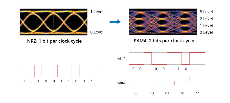
Pulse Amplitude Modulation 4-level (PAM4) is a technology that uses four different signal levels for signal transmission and each symbol period represents 2 bits of logic information (0, 1, 2, 3). By transmitting two bits in one symbol slot, PAM4 halves the signal bandwidth. Therefore, it is feasible to increase bandwidth by using advanced modulation PAM4 technology to increase the data rate without having to configure the data center with more fibers. 400 Gbps Ethernet can be realized with four lanes of PAM4 (8× 50 Gbps). This effectively doubles a network’s data rate, enabling 400G PAM4 for short-haul and long-haul transmission.

Why Does 400G Ethernet Need to Use PAM4 Technology?

In terms of supporting 400G Ethernet speed, the transmission rate of NRZ 25Gbps single channel has reached its limit, which cannot be adapted to the development of current high-density data centers. When discussing the 400GE IEEE 802.3bs standard, it was proposed to replace NRZ with PAM4 technology. So why is 400G PAM4 technology a viable alternative to NRZ?

Benefits of 400G PAM4

PAM4 modulation replaces 400G Ethernet using 16×25G baud rate NRZ and provides a path from 100G Ethernet using 4×25G baud rate to 400G Ethernet through 8×25G baud rate architecture. It is called 400G Ethernet The link adopts the 8×50G bit rate solution, reducing not only the fiber cost but also the link loss. For hyper-scale data centers, it’s time for them to transition from the previous 100G or Gigabit networks to 400G PAM4 Ethernet for faster transmission efficiency..

Compared to the NRZ signal, PAM4 has some better advantages. PAM4 carries 2 bits per symbol and transmits twice the NRZ information per symbol period. Hence, PAM4 doubles the bit rate for a given baud, thereby bringing higher efficiency to 400G transmission with greatly reduced signal loss. This key benefit of PAM4 allows existing channels and interconnects to be used at higher bit rates without doubling the baud rate and increasing channel loss..

PAM4 vs NRZ

Some information about the specific differences between PAM4 and NRZ. NRZ signaling uses two signal levels in which positive voltage defines bit 1 and the zero voltage defines bit 0. 1 bit signal is transmitted during a clock cycle.

PAM4 vs NRZ

Figure: PAM4 vs NRZ

Double Bit Rate – PAM4 doubles the bit rate for a given baud rate over NRZ. Thus, a 28 Gbaud PAM4 signal can deliver the same bit rate as a 56 Gbaud NRZ signal.

Less Signal Loss – PAM4 should let you develop 56 Gbps data lanes with less signal loss than would occur by simply doubling the NRZ (sometimes called NRZ-PAM2) bit rate. Exotic PCB materials can compensate for the deficiencies, but at a cost few are willing to pay.

400G PAM4 Transceivers: Multi-mode vs Singlemode

The 400G QSFP-DD transceivers modulation method uses PAM4 technology, including multi-mode and single-mode. In addition, the electrical port side of the 400G optical module supports 8x50G PAM4 modulation, and the optical port side supports both 8x50G PAM4 and 4x100G PAM4 modulation.

Both 400G SR8 and 400G SR4.2 multimode optical modules support 8x50G PAM4. 400G SR8 optical modules can use MPO-16 connectors or MPO-24 connectors to connect 8 pairs of fibers. The 400G SR4.2 modules use MPO-12 connectors, and the wavelengths are bidirectional and multiplexed.

According to the above mentioned, in the single-mode 400G optical module, the electrical port side is modulated with 4x100G PAM4, and a group of the optical port side is modulated with 8x50G PAM4. There are three common 8x50G PAM4 400G optical modules: FR8, LR8, and 2xFR4. 400G FR8 and 400G LR8 are the earliest available 400G single-mode interfaces, 8 wavelengths are multiplexed into one fiber, and duplex LC light is used at the same time. interface. The 2xFR4 400G optical module uses 8 lasers but is divided into two groups of 4 wavelengths according to the 200G FR4 standard.

400G optical modules modulated by 4x100G PAM4 are the focus of the current market, including 400G DR4, 400G FR4, and LR4, and their line-side uses four channels of 100G PAM4. In the 400G DR4 optical module, the DSP converts the 8x50G PAM4 electrical signal into 4x100G PAM4 and then transmits it to the optical engine.

Transceiver Solution Based on 400G PAM4

PAM4 is a relatively low-cost solution for 400GbE and data centers that has been adopted by the transceiver industry, enabling high-speed data rates, moving toward 400G and beyond. FS 400G transceivers apply 4×100G PAM4 or 8×50G PAM4 technology, which have been standardized by the IEEE working group, including 400GBASE-SR8, DR4, LR8, ER8, XDR4, FR4, and LR4. The FS 400G transceivers use a pluggable double-density design to support transmission requirements of different distances. At the same time, they can perform signal conversion through PAM4, and use multiplexing technology to convert transmission channels to achieve reasonable distribution of data center fiber resources.

StandardTransceiver TypesLink DistanceMedia TypeLanesPower Consumption
IEEE P802.3cm400GBASE-SR8100mMMF8× 50G PAM4<10W
IEEE 802.3bs400GBASE-DR4500mSMF4× 100G PAM4<10W
400GBASE-LR810kmSMF8× 50G PAM4<14W
IEEE P802.3cn400GBASE-ER840kmSMF8× 50G PAM4<14W
100G Lambda MSA400GBASE-XDR42kmSMF8× 50G PAM4<12W
400GBASE-FR42kmSMF4× 100G PAM4<12W
400GBASE-LR410kmSMF4× 100G PAM4<12W

Conclusion

As the market moves to PAM4-based modulation, more and more chip makers and transceiver vendors are manufacturing new 400G products using PAM4, transferring 400G PAM4 from theory to practice. PAM4 400G based on 50G PAM4 or 100G PAM4 will certainly become the basic rate of the next-generation Ethernet and stand out with its high performance and potential.

Article Source

https://community.fs.com/blog/pam4-for-400g-ethernet-applications.html

Related Articles

https://community.fs.com/blog/nrz-vs-pam4-modulation-techniques.html

https://community.fs.com/blog/400g-ethernet-400g-transceiver.html

How Many 400G Transceiver Types Are in the Market?

With the tremendous requirement for high bandwidth in 5G, loT and cloud data center, the focus of 400G Ethernet has been lasting for a couple of years. Vendors such as Cisco, Arista, and juniper are developing and testing technologies for 400G Ethernet networks. As the key hardware devices for interconnecting optical networks, there is no dispute that 400G transceiver will become the mainstream of the industry. Still curious about 400G transceivers? This paper will give you a comprehensive introduction to the different 400G transceiver types of different characteristics including applications, interface standards, and form factors.

Transceiver Application

According to the transceiver application, optical modules can be classified into two categories: client-side transceivers and line-side transceivers.

400G Ethernet Transceivers for Client Side Transmission

Client-side transceivers are used to interconnect between the metro networks and the optical backbone. The term “client side” refers to relatively short distances compared with the line side, generally from 50m to 10km and with only one transceiver connected to fiber thus no coherent optics is needed. There are various transceiver interfaces that have been standardized by IEEE and MSA. Most importantly, it has an agreed and standardized interface that is used for the network connection. PAM4 has been chosen by IEEE 802.3bs for 400GE client side transmission.

400G Coherent Transceivers for Line Side Transmission

Different from client side, line side reaches transmission distances of 80km or even longer using DWDM. Coherent technology is expected to implement 400G line side transmission. OIF has been working on standardizing the 400G coherent DWDM interface for DCI and other metro/access applications. The signal processing of coherent transport is much greater than that of short reach PAM4 data center transmission, which requires more DSPs and power than in client side transmission.

Interface Standard

The transceiver interfaces are defined by the interface standards. The following chart lists the common 400G Ethernet standards and the corresponding interfaces.

Interface standardInterfaceLink DistanceMedia TypeOptical Architecture
IEEE 802.3bs400GBASE-SR16100mMMF16× 25G NRZ 850nm
400GBASE-DR4500mSMF4× 100G PAM4 1300nm
400GBASE-FR82kmSMF8× 50G PAM4 WDM
400GBASE-LR810kmSMF8× 50G PAM4 WDM
IEEE P802.3cm400GBASE-SR8100mMMF8× 50G PAM4 850nm
400GBASE-SR4.2100mMMF8× 50G PAM4 BiDi 850/910nm
IEEE P802.3cn400GBASE-ER840kmSMF8× 50G PAM4 WDM
IEEE P802.3ct400GBASE-ZR80kmSMFCoherent DWDM
100G Lambda MSA400GBASE-FR42kmSMF4× 100G PAM4 CWDM
400GBASE-LR410kmSMF4× 100G PAM4 CWDM
CWDM8 MSA400G-CWDM8-22m to 2kmSMF8× 50G CWDM
400G-CWDM8-102m to 10kmSMF8× 50G CWDM

Note: 400GBASE-SR16 has not been released by any transceiver vendors. As 400GBASE-SR16 interface requires a high fiber count (32 fibers per duplex link), this standard is not expected to enter the 400G transceiver market.

400G Transceiver Form Factor

There are several mainstream 400G form factors,400G QSFP-DD, OSFP, CFP8, COBO, etc., some of which have been put in the market and some are still as a design.

  • CFP8 is the first generation 400G transceiver, with a relatively large physical size, offering the lowest port density.
  • COBO is named for Consortium for On-Board Optics, installed internally to the line-card equipment in a controlled environment, thus lacking flexibility.
  • OSFP stands for Octal Small Form Factor Pluggable, which is a new kind of pluggable form factor. There are some companies that have already sold 400G OSFP transceivers on the website.
  • 400G QSFP-DD transceivers are now one of the most popular optical modules in the market, which have been launched and manufactured by Finisar, Innolight, FS.COM, etc.QSFP-DD vs OSFP vs CFP8.jpg

The table below includes detailed comparisons of size, compatibility, power, etc. for the three main form factors: OSFP, QSFP-DD and CFP8.

OSFPQSFP-DDCFP8
Application ScenarioData center & telecomData centerTelecom
Size22.58mm× 107.8mm× 13mm18.35mm× 89.4mm× 8.5mm40mm× 102mm× 9.5mm
Max Power Consumption15W12W24W
Backward Compatibility with QSFP28Through adapterYesNo
Electrical signaling (Gbps)8× 50G8× 50G8× 50G
Switch Port Density (1RU)363616
Media TypeMMF & SMFMMF & SMFMMF & SMF
Hot PluggableYesYesYes
Thermal ManagementDirectIndirectIndirect
Support 800GYesNoNo

Among these three transceiver form factors, it is obvious CFP8 lacks density, unlike the other two 400G transceivers. OSFP modules have been designed with 800G in mind. The QSFP-DD form factor has the main advantages of its high density, small size, and back forward compatibility that it supports QSFP28 enabling easier migration to 400G Ethernet, which addresses the industry need for high speed and high-density networking. Therefore it is expected that QSFP-DD form factor will become the most appropriate form factor for the 400G Ethernet applications.

Summary

Apart from the above categories of 400G transceivers, fiber mode, wavelength, etc. are also the common characteristics that are used in optical transceiver classification, which are not further explained. The demand for high-speed data transmission is rocketing. As the transceiver market is pushed to shift, we can expect the 400G Ethernet deployment in the next-generation data centers and the popularity of 400G optical transceivers in the near future. Though both opportunities and challenges in the 400G transceiver test exist in the research stage, 400G Ethernet is still an inevitable trend.

Article Source

https://community.fs.com/blog/400g-ethernet-400g-transceiver.html

Related Articles

https://community.fs.com/blog/400g-qsfp-dd-transceiver-types-overview.html

https://community.fs.com/blog/400g-osfp-transceiver-types-overview.html

400G ZR vs. Open ROADM vs. ZR+

As global optical networks evolve, there’s an increasing need to innovate new solutions that meet the requirements of network operators. Some of these requirements include the push to maximize fiber utilization while reducing the cost of data transmission. Over the last decade, coherent optical transmission has played a critical role in meeting these requirements, and it’s expected to progressively improve for the next stages of tech and network evolution.

Today, we have coherent pluggable solutions supporting data rates from 100G to 400G. These performance-optimized systems are designed for small spaces and are low power, making them highly attractive to data center operators. We’ve discussed the 400G ZR, Open ROADM, and ZR+ optical networking standards below.

Understanding 400G ZR vs. Open ROADM vs. ZR+

Depending on the network setups and the unique data transmission requirements, data centers can choose to deploy any of the coherent pluggable solutions. We’ve highlighted key facts about these solutions below, from definitions to differences and applications.

What Is 400G ZR?

400G ZR defines a classic, economical, and interoperable standard for transferring 400 Gigabit Ethernet over a single optical wavelength using DWDM (dense wavelength division multiplexing) and higher-order modulation such as 16 QAM. The Optical Interoperability Forum (OIF) developed this low-cost standard for data transmission as one of the first standards to define an interoperable 400G interface.

400G ZR leverages an ultra-modern coherent optical technology and supports high-capacity point-to-point data transport over DCI links between 80 and 120km. The performance of 400ZR modules is also limited to ensure it’s cost-effective with a small physical size. This helps ensure that the power consumption fits within smaller modules such as the Quad Small Form-Factor Pluggable Double-Density (QSFP-DD) and Octal-Small Form-Factor Pluggable (OSFP). The 400G ZR enables the use of inexpensive yet modest performance components within the modules.

400G ZR

What Is Open ROADM?

This is one of the 400G pluggable solutions that define interoperability specifications for Reconfigurable Optical Add/Drop Multiplexers (ROADM). The latter comprises hardware devices that manage and route data traffic transported over high-capacity fiber-optic lines. Open ROADM was first designed to combat the surge in traffic on the wireless network experienced between the years 2007 and 2015.

The key components of Open ROADM include ROADM switch, transponders, and pluggable optics – all controllable via open standards-based API accessed via an SDN Controller utilizing the NETCONF protocol. Launched in 2016, the Open ROADM initiative’s main objective was to bring together multiple vendors and network operators so they could devise an agreed approach to design networks that are scalable, cost-effective, and flexible.

This multi-source agreement (MSA) aims to shift from a traditionally closed ROADM optical transport network toward a disaggregated open transport network while allowing for centralized software control. Some of the ways to disaggregate ROADM systems include hardware disaggregation (e.g., defining a common shelf) and functional disaggregation (less about hardware, more about function).

The Open ROADM MSA went for the functional disaggregation first because of the complexity of common shelves. The team intended to focus on simplicity, concentrating on lower-performance metro systems at the time of its first release. Open ROADM handles 100-400GbE and 100-400G OTN client traffic within a typical deployment paradigm of 500km.

Open ROADM

What Is ZR+?

The ZR+ represents a series of coherent pluggable solutions holding line capacities up to 400 Gb/s and stretching well past the 120km specification for 400ZR. OpenZR+ was designed to maintain the classic Ethernet-only host interface of 400ZR while adding support to aid features such as the extended point-to-point reach of up to around 500km and the inclusion of support for OTN Ethernet, etc.

The recently issued MSA provides interoperable 100G, 200G, 300G & 400G line rates over regional, metro, and long-haul distances, utilizing OpenFEC forward error correction and 100-400G optical line specifications. There’s also a broad range of coverage for ZR+ pluggable, and these products can be deployed across routers, switches, and optical transport equipment.

ZR+

400G ZR, Open ROADM, and ZR+ Differences

Target Application

400ZR and OpenZR+ were designed to satisfy the growing volume requirements of DCI and cloud operators using 100GbE/400GbE client interfaces, while OpenROADM provides a good alternative for carriers that require transporting OTN client signals (OTU4).

In other words, the 400ZR efforts concentrate on one modulation type and line rate (400G) for metro point-to-point applications. On the other hand, the OpenZR+ and Open ROADM groups concentrate on high-efficiency optical specifications capable of adjustable 100G-400G line rates and lengthier optical reaches.

400G Reach: Deployment Paradigm

400ZR modules support high-capacity data transport over DCI links of up to 80 to 120km. On the other hand, OpenZR+ and OpenROADM, under perfect network presumption, can transmit the network for up to 480 km in 400G mode.

Power Targets

The power consumption targets of these coherent pluggable also vary. For instance, the 400zr has a target power consumption of 15W, while Open ROADM and ZR+ have power consumption targets of not more than 25W.

Applications for 400G ZR, Open ROADM and ZR+

Each of these coherent pluggable solutions finds use cases in various settings. Below is a quick summary of the three data transfer standards and their major applications.

  • 400G ZR – frequently used for point-to-point DCI (up to 80km), simplifying the task of interconnecting data centers.
  • Open ROADM – This architecture can be deployed using different vendors, provided they exist in the same network. It gives the option to use transponders from various vendors at the end of each circuit.
  • ZR+ – It provides a comprehensive, open, and flexible coherent solution in a relatively smaller form factor pluggable module. This standard addresses hyperscale data center applications for high-intensive edge and regional interconnects.

A Look into the Future

As digital transformation takes shape across industries, there’s an increasing demand for scalable solutions and architectures for transmitting and accessing data. The industry is also moving towards real-world deployments of 400G networks, and the three coherent pluggable solutions above are seeing wider adoption.

400ZR and the OpenZR+ specifications were developed to meet the network demands of DCI and cloud operators using 100 and 400GbE interfaces. On the other hand, Open ROADM offers a better alternative for carriers that want to transport OTN client signals. Currently, Open ZR+ and Open ROADM provide more benefits to data center operators than 400G ZR, and technology is just getting better. Moving into the future, optical networking standards will continue to improve both in design and performance.

Article Source: 400G ZR vs. Open ROADM vs. ZR+
Related Articles:

ROADM for 400G WDM Transmission

400G ZR & ZR+ – New Generation of Solutions for Longer-reach Optical Communications

FS 400G Cabling Solutions: DAC, AOC, and Fiber Cabling