Category Archives: Fiber Testers & Tools

DWDM MUX/DEMUX Insertion Loss Test

During the selection of a DWDM MUX/DEMUX, the insertion loss should always be considered. Generally, a report including the insertion loss value of each port on the DWDM MUX/DEMUX, is usually attached with the product. These values are tested by professional testers. This post will illustrate how to test the insertion loss of DWDM MUX/DEMUX by using an easy-to-get optical power meter.DWDM MUX insertion loss test
Products Required for Insertion Loss Test

We will use Cisco Catalyst 4948E switch and Cisco compatible DWDM SFP+ modules as light source to test the insertion loss of a 40-CH DWDM MUX/DEMUX provided by FS.COM. This DWDM MUX/DEMUX has a typical insertion loss of 3.0 dB. Channel 25 port and Channel 60 port will be tested. The products and tools required are listed as following:

DWDM MUX/DEMUX Insertion Loss Test Steps

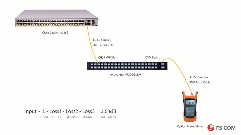
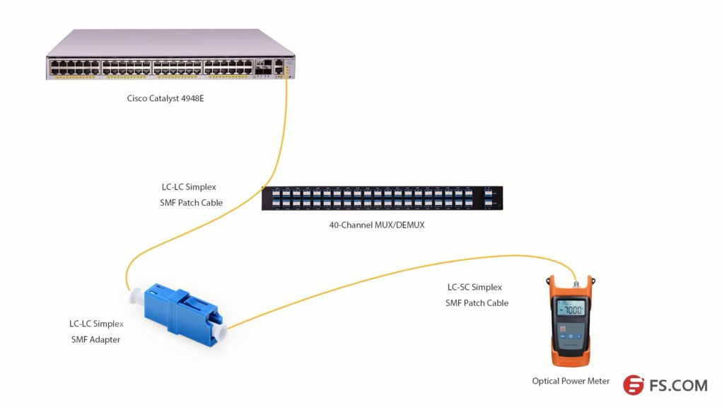
First, install the 80km C25 DWDM SFP+ module in the SFP+ port of Cisco Catalyst 4948E. Second, connect the Tx port of the SFP+ module to the Rx port of Channel 25 port with a length of LC-LC simplex single-mode patch cable. Then, connect the TX port of the COM port to the optical power meter with a length of LC-SC simplex single mode patch cable.

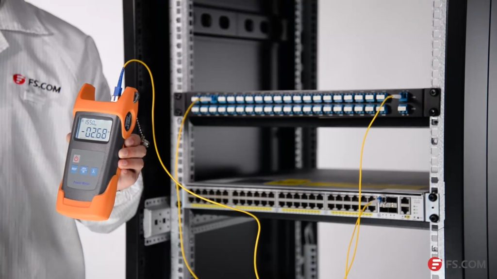
Please note to clean all the optical interfaces before connecting to ensure the accuracy of the testing result. The connection is shown in the following picture.
DWDM insertion loss test

Press the λ button to select the wavelength of 1550nm. Then, we will get the optical power value (2.68dB) of the signal from C25 80km DWDM SFP+ module. Light loss occurs when the optical signal pass LC-LC simplex SMF patch cable (Loss1), CH25 port, LC-SC simplex SMF patch cable (Loss2) and COM port (Loss 3) as shown in the above picture.

We get a simple formula here:

Input power – Insertion Loss (CH25) – Loss1-Loss2 -Loss3 = 2.68dB (REF value)

If we want to get the insertion loss value of Channel 25, the formula will be:

Insertion Loss (CH25) = Input power – Loss1 -Loss2 -Loss3 – 2.68dB (REF value)

We can set the 2.68dB as the reference value. And if we can test the optical power value of the channel 25 SFP+ after it experienced these three loss points, the difference value will be the insertion loss of the channel 25 channel port.
DWDM insertion loss test

As the com port could be regarded as an adapter, we will use an adapter to connect the LC-SC and LC-LC patch cables together. Then, connect them to the optical power meter as shown in the above picture, we can get the difference value which is 3.58dB. This value is the insertion loss of the Channel 25 port on this 40Ch DWDM MUX/DEMUX. This value might not be very accurate value, but it is close to it.

DWDM MUX/DEMUX Insertion Loss Testing Video


We have taken a video about how to test the 40CH DWDM MUX/DEMUX insertion loss with optical power meter. You can get more details in this video. All the products and tools in this video are provided by FS.COM. Kindly contact sales@fs.com or visit FS.COM for more if you are interested.

Overcome OTDR Dead Zone With Launch Fiber

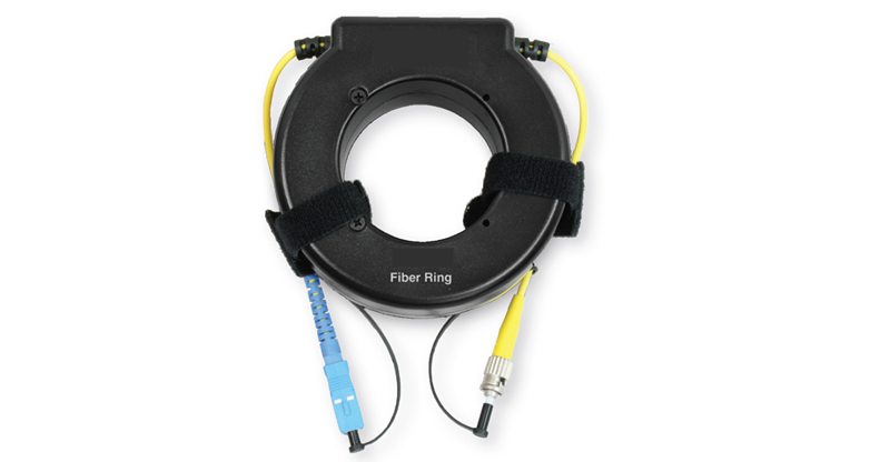
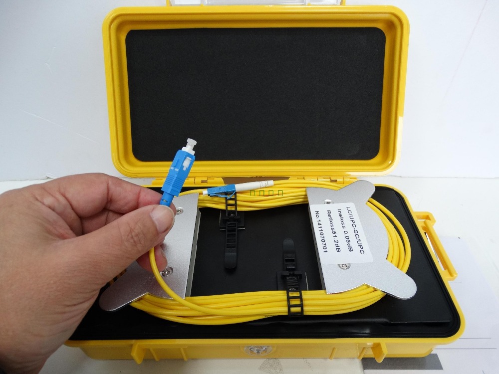
OTDR is a popular fiber optic testing tool which can be used to test the fiber loss, and locate the faults in fiber optic links. However, the OTDR dead zone will affect the testing result and the application of OTDR. To overcome OTDR dead zone during fiber optic testing, launch fiber is being added between OTDR and optical fiber link under test. OTDR launch fiber comes in different types of packages. OTDR launch box and OTDR launch fiber ring are the most commonly used launch fibers.

Why Can Launch Fiber Overcome OTDR Dead Zone?

OTDR insert pulses of light into fiber optic link and measure the back reflection caused by fiber faults to locate the faults. If a long fiber link is required to be tested, a lot of optical power should be inserted into the optical fiber to make sure that the light can be seen at the other end. If powerful optical pulses are inserted into optical fiber, pulse width of the launched optical signal will be increased, which will cause the dead zone at a length of fiber and affect the testing result of OTDR. This dead zone might be hundreds or thousands meters long.

OTDR launch box

To minimize the affection of the OTDR dead zone during fiber optic testing. A length of long enough optical fiber is being added between the OTDR and the fiber under test. In this way, the OTDR dead zone will happen in this additional optical fiber. The launch fiber is actually a length of optical fiber which is long enough to cover the OTDR dead zone to increase the testing accuracy. Launch fiber is usually terminated with a connector on each end to connect the OTDR with the fiber link under test.

launch fiber

OTDR Test With Launch Fiber

OTDR launch fiber mainly has two designs, one is fiber ring design and the other is box design, separately known as launch fiber ring and OTDR launch box or OTDR dead zone box. The using of them is generally the same. Here offer two situations about how to use OTDR launch fiber.

OTDR testing with launch fiber

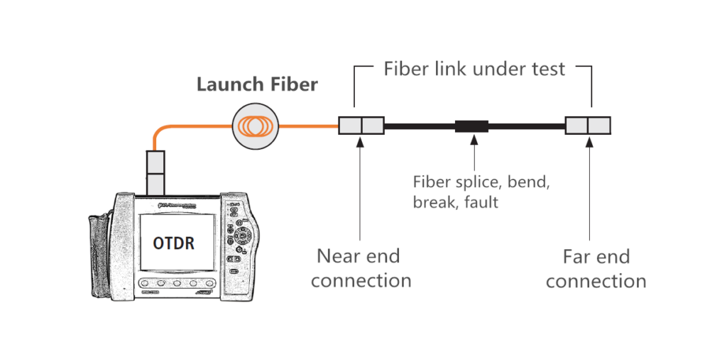
In some cables, launch cable is being used to cover the dead zone at the beginning of the fiber link. In these cases, OTDR launch fiber or OTDR launch box is deployed between the OTDR and the near end connection as shown in the above picture. This allows the accurate measurement of the fiber loss at the near end connection.

OTDR and launch fiber

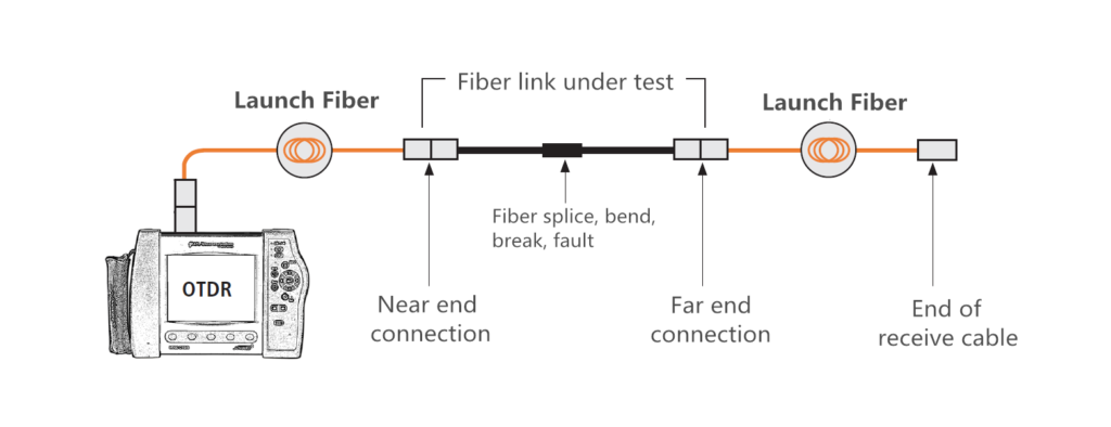
In some cases, the fiber loss at the far end connection should also be tested. Then, the launch fiber can be installed added at the far end connection to work as a receive cable, as shown in the above picture.

Please note that the launch fiber you used for testing should have the same fiber types (OS2, OM1, OM2, OM3, OM4) as the optical fiber under test.

Conclusion

Using launch fiber to overcome OTDR dead zone is the choice in most cases, especially for long optical fiber testing. Let the OTDR dead zone occur in the launch cable to ensure the accurate testing result. Launch fiber is suggested to be added at the beginning and the end of the fiber optic link, if the light loss of the whole fiber link is required. If you want to need more specific details about OTDR launch box, kindly visit another article: Why Do You Need OTDR Launch Box

How to Use Optical Power Meter

To ensure the signal transmission performance in fiber optic network, optical power should be well controlled. Optical power should not be too high or too low. And it should be within the scope of the device’s requirement. To achieve accurate measurement, optical power meter is usually used to test the optical power. But How to use optical power meter? This post will make an illustration of the power meter components and then state how to use optical power meter.

Buttons on Optical Power Meter

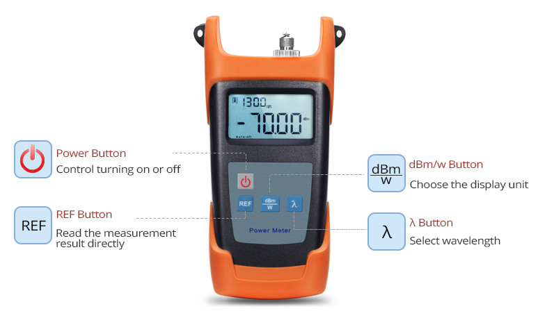
The functions and operation of optical power meters provided by the market are similar. Generally there are four buttons on the optical power meter: power button, dBm/w button, REF button and λ button. The functions of these buttons are listed in the following:

  • Power button: turn the power meter on or off;
  • dBm/w button: shift between linear (mW) mode and logarithmic (dBm) mode;
  • REF button: press this button to set the current measured power as the referent point;
  • λ button: select the calibrated wavelength. The most commonly used wavelengths are 850nm, 980nm, 1310nm, and 1550nm.

Here takes an example of a typical handheld optical power meter (FOPM-104) which is designed by FS.COM as shown in the following picture.how to use optical power meter: buttons

Adapter Type of Optical Power Meter

To use the optical power meter, a length of fiber optic patch cable is usually required to connect the optical power meter interface and the interface of devices requiring test. For instance, if the interface on the fiber optic power meter is FC, the device for testing has a LC interface. Then a length of FC-LC fiber patch cable is needed. Some of the optical power meters have only one fixed optical interface. Some can provide replaceable optical adapter to fit different patch cables. The above mentioned FOPM-104 handheld optical power meter provides three type adapters: SC, FC and ST (as shown in the following picture).optical power meter adapter

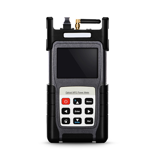
For testing of fiber optic interface like LC, SC, ST and FC, this above power meter is enough. Some optical power meter might have two optical interfaces for common connectors. However, interface like MTP/MPO, optical power meter with special interface should be used. The following picture shows a MTP optical power meter provided by FS.COM, which can be used to test devices or components with MTP interfaces like 40G SR4 QSFP+ transceiver.how to use optical power meter: adapter types

Optical Power Measurement Using Optical Power Meter

How to use optical power meter? It can be easy. The following video will take the example of 10G-LR SFP+ Cisco compatible module to illustrate how to use optical power meter for testing. This cisco compatible transceiver will be inserted in Cisco Nexus 9396PX switch. A length of single-mode LC-FC fiber patch cable is required. This is because 10G-LR SFP+ transceiver is a single-mode transceiver working on wavelength of 1310nm. After the optical power meter is connected to the module. Turn on the power button and press λ button to select 1310nm wavelength. At first the power value will change rapidly, then it slows down until still. The final power value will be shown on the screen.

Conclusion

This post introduces the buttons and adapter types of optical power meters, and illustrates how to use optical power meter with the aid of both text and video. Kindly visit Optical Power Meter page or contact sales@fs.com for more details.

Related Article: DWDM MUX/DEMUX Insertion Loss Test

                             Optical Power Meter (OPM): A Must for Fiber Cable Testing

Causes of Mechanical Splice Termination Failures

FTTH (fiber to the home) has become increasingly popular in optical communication industry. Fiber optic termination, as one of the topics which have never been out of fashion in this field, has naturally become a focus of FTTH network deployment, especially the indoor termination. In FTTH network, mechanical splice connectors are usually used in FTTH indoor termination with the advantages of flexibility, fast-installation and cost-effective. Currently manufactures can provide various types of mechanical splice connectors of high quality which have low insertion loss and high performance. However, no matter how excellent the mechanical splicing technology is, there are still fiber optic termination failures and bad fiber optic termination due to improper operation. To avoid it, this post is to offer the causes of mechanical splice termination failures.

The Basic of Mechanical splicing

Before finding the cause of mechanical splice failure, the basic of mechanical splicing should be introduced. To finish a mechanical splice, the buffer coatings of fiber optic should be removed mechanically with sharp blades or calibrated stripping tools. In any type of mechanical stripping, the key is to avoid nicking the fiber. Then the fibers will be cleaved. Two fiber ends are then held closely in retaining and aligning a mechanical splice connector with some index matching gel between them. The gel are used to form a continuous optical path between fibers and reduce reflecting losses.

mechanical splicing

Causes of Mechanical Splice Termination Failures

Mechanical splice connector is sensitive to many factors. There are also a large number of factors to cause failures. However, most of the factors are located at the end face of fiber optic. The following is to describe them in details.

Contamination

When facing mechanical splice failures, there would be no argument that contamination is the first thing to think about. There are many ways that contamination can be carried into the fiber termination splices. Generally, there are the following possible causes of splice contamination:

  • Using a dirty cleave tool: as the fiber should be cleave before inserted in the connector, a fiber optic cleaves would be used. If a dirty cleave is used, the contamination would be attached on the end face of the fiber optic and be embedded in the connector. Thus, do remember to clean the surfaces thoroughly with alcohol wipes;
  • Wiping the fiber after cleaving;
  • Setting the connector or fiber down on a dusty surface;
  • Heavy airborne dust environment;
  • Glass fragments from insertion broken fibers, or applying excessive force;
  • Polluted index matching gel.

comtamination

Please note that once the contamination is carried inside the mechanical splice connector, especially with the index matching gel, there would be little possibility to clean them out, which means the connector may be scrapped.

Glass Fragmentation

Improper operation like overexertion when inserting the fiber optic into the mechanical splice connector might break the fiber optic and produce glass fragmentation which will cause air gap and optical failure. Or if a broken fiber if inserted, there will also be optical failure. If the glass fragments are embedded in the connector, they cannot be cleaned out and the connector would be scrapped. Thus, be gentle and carefully when splicing the fiber ends.

glass-fragmentation

Bad Cleave

Cleaving the fiber optic is an important step during fiber optic mechanical splicing. The quality of the cleave can decide the quality of the optical splice transmission to some degree. It is not easy to inspect the cleave quality in the field. There are several possibilities there might cause the bad cleaves:

  • Dull or chipped cleave tool blade
  • The bent tongue on the cleave tool concentrated too much bend stress on the fiber
  • Bending the fiber too much or too tight of a radius
  • Applying no tension or insufficient tension to the fiber while cleaving.

bad cleave

Excessive Fiber Gap

Fiber gap is another factor that might cause the fiber optic termination failure. The fiber optic transmission is very sensitive to the gap between two fiber ends in the mechanical splice connector. Improper operations that might cause the excessive fiber gap are listed as following:

  • Cleaving the fiber without enough lengths;
  • The fiber is not fully inserted, or pulled back during termination;
  • The fiber was not held steady during termination and was pushed back into the fan-out tubing when terminating outdoor cable.

These faults can be corrected one time.

fiber gap

Excessive Cleave Angle

During fiber cleaving, cleave angle can be produced easily and is difficult to be inspected in field. These angles are typically ranging from 1 to 3 degree. Even with precision tool, there might still be cleave angle ranging from 0.5 to 1 degree. The angle is generally produced by bent tongue, fiber bending or insufficient fiber tension.

cleave-angle

However the cleave angles can be corrected by fine tuning with a VFL (visual fault locator). Rotating the fiber while using a VFL and terminate the connector at the position (as shown in the following picture).

VFL-tuning-fiber

Conclusion

Fiber optic mechanical splicing gives quick and high quality result at a low price for fiber optic termination. Choosing the right fiber optic mechanical splice connector and fiber optic cleaver of high quality is not enough. Acknowledge the possible causes to fiber optic termination failures and use the right tools with skills can reduce the risk of termination failure effectively.

Source: http://www.fs.com/blog/causes-of-mechanical-splice-termination-failures.html

Visual Fault Locator Overview

Whether install new fiber links or troubleshooting an existing network, the faster you can locate a problem, the faster you can fix it. To locate the faults in fiber optic cables in a short time, various fiber optic testers are being invited to locate the faults of the fiber optic cable, like OTDR (optical time-domain reflectometer). However, OTDR has dead zone during the testing. Another simple and useful tester which can work in an OTDR dead zone is usually being used to work as an accessory of OTDR. It is known as VFL (visual fault locator) which can also work alone to locate the faults in fiber optic cable in a time saving manner in some situations.

What Is VFL?

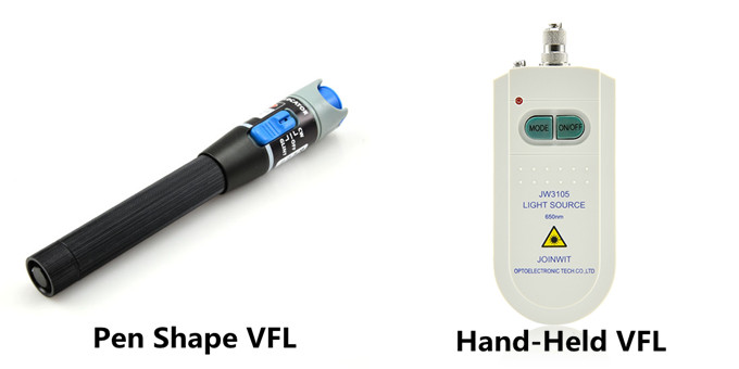
Visual fault locator is now one of the most commonly used fiber optic testing devices to trace optical fibers, check fiber continuity and find faults such as breaks, bad splices and tight, sharp bends in fiber optic cable. The most popular visual fault locators are pen shape VFL and hand-held VFL, which are showed in the following picture respectively.

Visual Fault Locator

How VFL Works

The light used for transmit signals over fiber optic is usually at 1300 to 1650nm wavelength which is invisible to naked eyes. Unlike OTDR which measures the time of the incidence and the amplitude of the reflected pulses sent to the fiber optic cable to locate the faults, VFL uses powerful visible light at the 360 to 670nm wavelength injecting to a fiber to visually and directly locate the faults in fiber optic cable. The visible light travels along the core until it reaches a fault, where it leaks out. Light leaking through the fault can be seen through plastic coating and jackets under suitable illumination. This is how VFL locates the faults in fiber optic cable.

Visual fault locators radiate in continuous wave (CW) or pulse modes. The glint of the light source in VFL is usually at 1 or 2 Hz, kHz range is also being provided in today’s market. The output power is generally at 1 mW or less. The working distance of a VFL is usually in the range of 2 to 5 km.

How to Use VFL

VFL is very easy to use. The steps to use a VFL are provided as following:

  • Step One: remove the plastic connector covers from both ends of the test fiber cable.
  • Step Two: connect the fiber optic visual fault locator one end of the fiber. Press the tester button and observe that light emanates from the other end of the fiber. This gives a simple indication of the continuity of the fiber link.
  • Step Three: repeat with several other fibers. Check for light that can be seen leaking from a faulty splice. This may illustrate an easy way of carrying out visual fault finding on bad splices or joints.
  • Step Four: disconnect all equipment, put the plastic covers back on the connector ends and return everything to the state it was in before you started the practical so that the next group can carry out the practical in full.

VFL

Notes during the using of a VFL:

  • 1.Never look directly into the VFL’s output.
  • 2.Cover the VFL’s output with the dust cap when the VFL is not in use.
  • 3.Not recommended for use on dark colored or armored cables.

Using simple but useful technical principle, visual fault locator individually can provide an economic and time saving solution to locator faults in fiber optic cables in some cases. While working as an accessory of OTDR, VFL, together with OTDR, can provide the fiber technician the best solution to locate fiber faults.