Category Archives: Fiber Cabling

DWDM MUX/DEMUX Insertion Loss Test

During the selection of a DWDM MUX/DEMUX, the insertion loss should always be considered. Generally, a report including the insertion loss value of each port on the DWDM MUX/DEMUX, is usually attached with the product. These values are tested by professional testers. This post will illustrate how to test the insertion loss of DWDM MUX/DEMUX by using an easy-to-get optical power meter.DWDM MUX insertion loss test
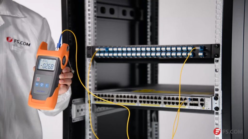
Products Required for Insertion Loss Test

We will use Cisco Catalyst 4948E switch and Cisco compatible DWDM SFP+ modules as light source to test the insertion loss of a 40-CH DWDM MUX/DEMUX provided by FS.COM. This DWDM MUX/DEMUX has a typical insertion loss of 3.0 dB. Channel 25 port and Channel 60 port will be tested. The products and tools required are listed as following:

DWDM MUX/DEMUX Insertion Loss Test Steps

First, install the 80km C25 DWDM SFP+ module in the SFP+ port of Cisco Catalyst 4948E. Second, connect the Tx port of the SFP+ module to the Rx port of Channel 25 port with a length of LC-LC simplex single-mode patch cable. Then, connect the TX port of the COM port to the optical power meter with a length of LC-SC simplex single mode patch cable.

Please note to clean all the optical interfaces before connecting to ensure the accuracy of the testing result. The connection is shown in the following picture.
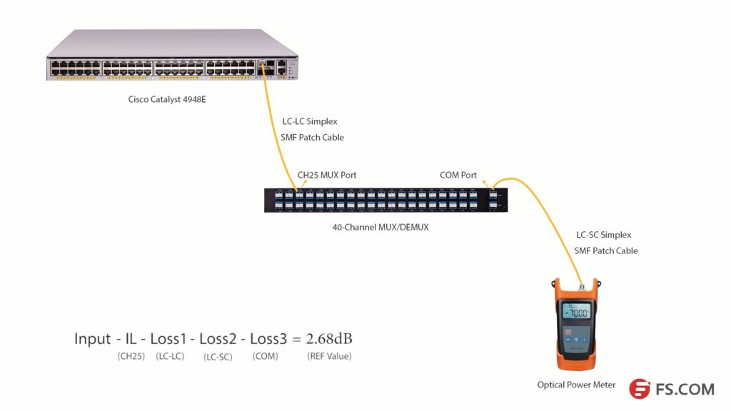
DWDM insertion loss test

Press the λ button to select the wavelength of 1550nm. Then, we will get the optical power value (2.68dB) of the signal from C25 80km DWDM SFP+ module. Light loss occurs when the optical signal pass LC-LC simplex SMF patch cable (Loss1), CH25 port, LC-SC simplex SMF patch cable (Loss2) and COM port (Loss 3) as shown in the above picture.

We get a simple formula here:

Input power – Insertion Loss (CH25) – Loss1-Loss2 -Loss3 = 2.68dB (REF value)

If we want to get the insertion loss value of Channel 25, the formula will be:

Insertion Loss (CH25) = Input power – Loss1 -Loss2 -Loss3 – 2.68dB (REF value)

We can set the 2.68dB as the reference value. And if we can test the optical power value of the channel 25 SFP+ after it experienced these three loss points, the difference value will be the insertion loss of the channel 25 channel port.
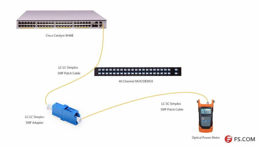
DWDM insertion loss test

As the com port could be regarded as an adapter, we will use an adapter to connect the LC-SC and LC-LC patch cables together. Then, connect them to the optical power meter as shown in the above picture, we can get the difference value which is 3.58dB. This value is the insertion loss of the Channel 25 port on this 40Ch DWDM MUX/DEMUX. This value might not be very accurate value, but it is close to it.

DWDM MUX/DEMUX Insertion Loss Testing Video


We have taken a video about how to test the 40CH DWDM MUX/DEMUX insertion loss with optical power meter. You can get more details in this video. All the products and tools in this video are provided by FS.COM. Kindly contact sales@fs.com or visit FS.COM for more if you are interested.

8-Fiber MTP VS. 12-Fiber MTP Cables

MTP fiber cable in data center becomes increasingly popular in data center with the wide deployment of 40G and 100G network. It is common that 40G and 100G network usually based on 12-fiber MTP networking system. However, not all the 12 fibers of MTP cable are used.8-fiber MTP cable

12-Fiber MTP Cable During Transmission

There are usually 4 fibers left unused, if you are using a 12-fiber MTP cable to transmit 40G with QSFP+ module or 100G with QSFP28 module. The following shows how 12-fiber MTP fiber cable works when it is used to be connected with 40Gbase-SR4 QSFP+ module. If more 12-fiber MTP cables are used, more optical fibers will be wasted. As IEEE standards like 40GBASE-SR4 and 40GBASE-SR10 uses only 8 fibers for dual-way transmission, manufacturers provide new versions of MTP fiber cable which contains only 8 optical fibers but still used the standard MTP interfaces.40gbase-sr4

Base-8 MTP for Higher Density and Lower Utilization

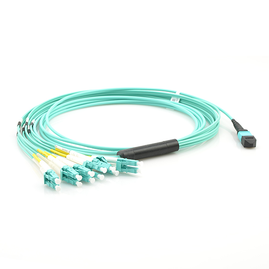
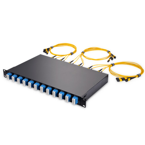
Network built with 8-fiber MTP system can transmit the same data with less cost and higher density compared with 12-fiber MTP system. All fiber will be 100% utilized in base-8 MTP products. It could be a cost-effect solution for both 40G to 40G transmission and 40G to 10G transmission. 8-fiber MTP trunk cables and 8-fiber MTP-LC harness cable are already provided in the market. There are also rack designed 8-Fiber MTP breakout panels for 40G to 10G applications.

MTP-LC-harness-cable MTP-LC-harness-cable
MTP-LC Harness Cable MTP-LC 40/100G Breakout Panel

Convert 12-Fiber MTP to 8-Fiber MTP Cabling System

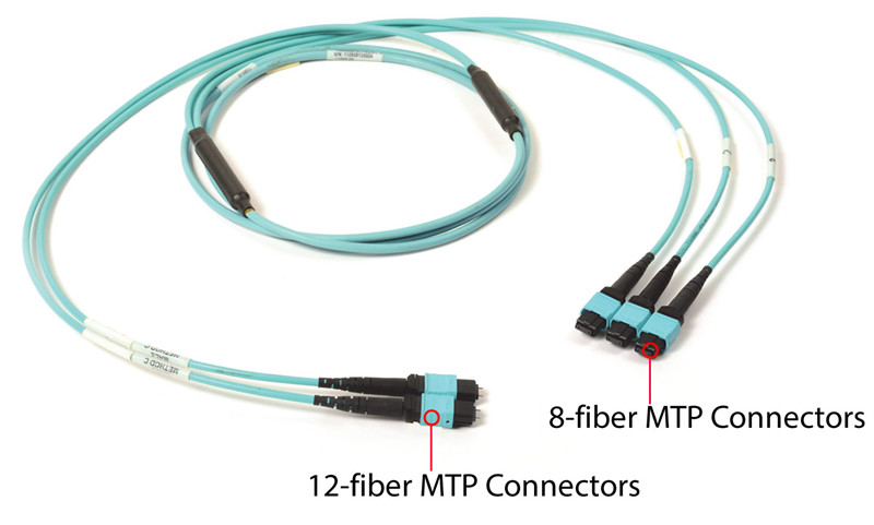
However, most MTP cabling systems are based on 12-fiber or 24-fiber MTP system, especially for backbone cabling. MTP conversion cables are provided in the market which offer conversion between 12/24-fiber MTP and 8-fiber MTP cabling systems. The following shows two types of 8-fiber MTP conversion cables which can provide 12-fiber to 8-fiber MTP conversion and 24-fiber to 8-fiber MTP conversion separately.

24 to 8 fiber MTP conversion cable 12 to 8 fiber MTP conversion cable
1*3 MTP Conversion Cable 2*3 MTP Conversion Cable

If you have already deployed 12-fiber MTP cabling system in your data center, 2*3 MTP conversion cable is suggested to be used. With one end terminated with two 12-fiber MTP cable and the other end terminated with three 8-fiber MTP connectors, 12-fiber to 8-fiber MTP cabling conversion could be achieved, as well as 100% optical fiber utilization in 12-fiber MTP system.

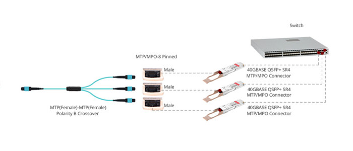
1*3 MTP conversion cable has a 24-fiber MTP cable on one end and three 8-fiber MTP cable on the other end. With this cable, a length of 24-fiber MTP cable can provide three ways of 40G signal dual-way transmission. All the fibers in a 24-fiber cabling system cable be used.

Conclusion

It is clear that the 8-fiber, 12-fiber based and 2-fiber based cabling system will exist for a long term in 40/100G network. 8-fiber MTP cabling system can provide higher optical fiber utilization with lower cost and higher cabling density. If you want to transfer 12-fiber MTP system to 8-fiber MTP system, you can use MTP conversion cables. 8-base MTP system, could be regarded as an additional option for the existing fiber network infrastructure.

MTP Conversion Cable and Its Usage

12-fiber MTP and 24-fiber MTP cables are widely used in 40G and 100G high density cabling. However, in many cases, not all the fibers are used. For instance, to connect a 40G-SR4 QSFP+ module, we usually use a 12-fiber MTP cable with only 8 fibers in use. If you have built a 24-fiber cabling system, you can use MTP conversion cable to make full use of the existing optical fibers.

MTP conversion cable

MTP Conversion Cable

Unlike MTP-LC harness cable, MTP conversion cables are terminated with MTP connectors on both ends. However, the MTP connectors on each end are different in fiber counts and types. MTP conversion cable can provide more possibilities for the existing 24-fiber cabling system. The following are the most commonly used MTP conversion cable:

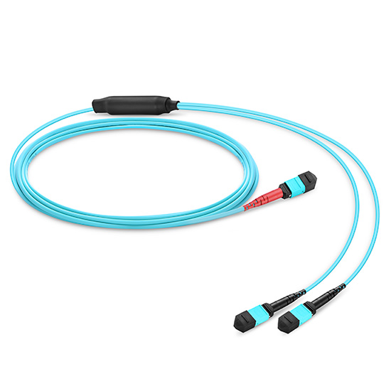
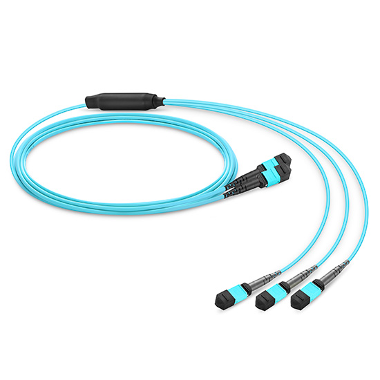
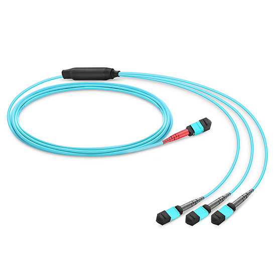
1*2 MTP conversion cable 2*3 MTP conversion cable 1*3 MTP conversion cable
1*2 MTP conversion cable 2*3 MTP conversion cable 1*3 MTP conversion cable
24-Fiber MTP to 2*12-Fiber MTP 2*12-Fiber MTP to 3*8-Fiber MTP 24-Fiber MTP to 3*8-Fiber MTP
MTP Conversion Cable Application

The total fiber counts of the above three MTP conversion cables are all 24. But the can provide different connections in multi-fiber cabling system. The following will introduce the applications of these cables.

1*2 MTP Conversion Cable

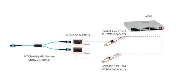
This MTP conversion cable has one end terminated with a 24-fiber MTP connector and the other end terminated with two 12-fiber MTP connector. With this cable, two 12-fiber optical singles can be transferred on to a 24-fiber cable for transmission. In multimode cabling system, the optical signals of two 40G-SR4 QSFP+ modules can be transmitted over a single 24-fiber MTP cable as shown in the following picture.

1*2 MTP conversion cable
1*3 MTP Conversion Cable

1*3 MTP conversion cable has one 24-fiber MTP connector terminated on one end and three 8-fiber MTP connector one the other end. The 8-fiber MTP connectors can be connected to 40G-SR4 QSFP+ modules. This MTP conversion cable utilizes 100% of the existing 24 optical fibers. Each fiber can be used to transmit 10G optical data. Three 40G dual-way transmissions can be achieved on the existing 24-fiber MTP cable. It can also be used to breakout the 120G CXP module signals into three 40G QSFP+ SR4 optical signals.

1*3 MTP conversion cable
2*3 MTP Conversion Cable

2*3 MTP conversion cable is terminated with two 12-fiber MTP connectors and three 8-fiber MTP connectors. This MTP conversion cable allows three 40G-SR4 optical signal transmit on the existing two 12-fiber MTP trunk cables as shown in the following. If you have built a 12-fiber MTP cabling system. This 2*3 MTP conversion cable can increase about 30% capacity of the existing network.

2*3 MTP conversion cable

MTP Conversion Cable Selection

MTP conversion cables are designed to provide a more flexible multi-fiber cabling system based on MTP products. It can largely increase the capacity of the existing 12-fiber and 24-fiber MTP network. The above mentioned MTP conversion cable in different fiber types and cable lengths. Kindly contact sales@fs.com for more details if you are interested.
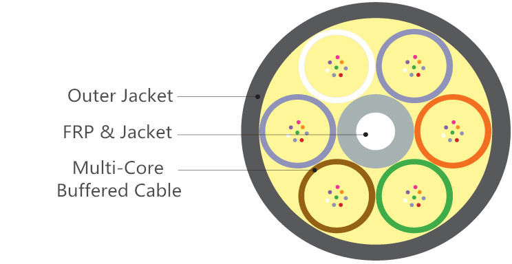
Which Tight Buffered Fiber Distribution Cable Fits Your Application?

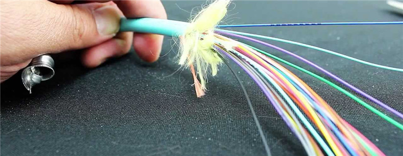
Optical fibers with fiber counts ranging from 2 to 144 counts or more are usually coated together inside a single strand of fiber optic cable for better protection and cabling. Multi-fiber optic cables are usually required to pass a lot of distribution points. And each individual optical fiber should connect only one specific optical interface via splicing or terminating by connectors. Thus, fiber optic cables used for distribution should be durable and easy to be terminated. Tight buffered fiber distribution cables, which meet these demands, are widely used in today’s indoor and outdoor applications, like data center and FTTH projects. This post will introduce tight buffered fiber distribution cables.

tight buffered fiber cable

The Beauty of 900um Tight Buffered Fibers

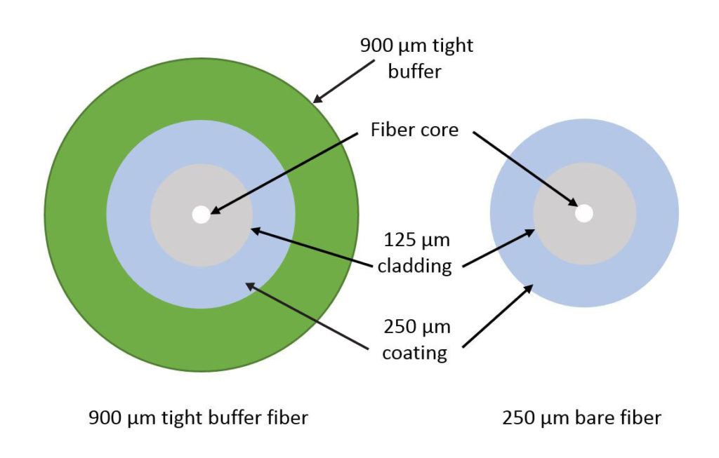
Most of tight buffered fiber distribution cables are designed with 900um tight buffered fibers. This is decided by its applications. As the above mentioned, the distribution cable should be durable and easy to be terminated. The following picture shows the difference between 250um bare fiber and 900um tight buffered fiber. They are alike, but the tight buffered fiber has an additional buffer layer. Compared with bare fibers, 900um tight buffered fibers can provide better protection for the fiber cores. 900um tight buffered fibers are easy to be stripped for splicing and termination. In addition, tight buffered fiber cables are usually small in package and flexible during cabling. These are the main reasons why a lot of fiber optic distribution cables use tight buffered design.

250um vs 950um

Choose Tight Buffered Distribution Fiber Cables According to Applications

900nm tight buffered distribution fiber cables also come in a variety of types. Tight buffered distribution fiber cables used for different environments and applications might have different fiber types, outer jackets and cable structures. The following will introduce several tight buffered distribution fiber cables for your reference.

unitized distribution fiber cable
Indoor Tight Buffered Distribution Fiber Cable

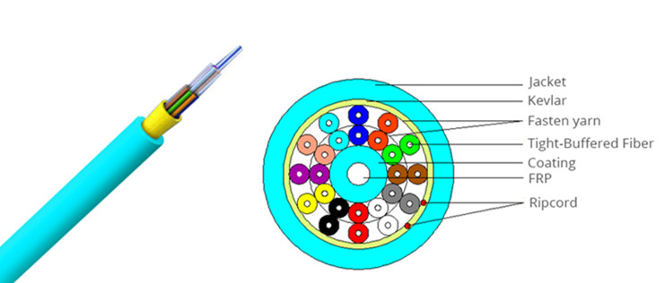
Tight buffered distribution fiber cables used for indoor applications are usually used for intra building backbones and routing between telecommunication rooms. Large tight buffered fiber cable with fiber counts more than 36 fibers generally has “sub-unit” (unitized) design (shown in the above). While smaller tight buffered distribution cables, with fiber counts of 6, 12 or 24, usually have “single-jacket” (non-unitized) designs, which are more flexible in cabling and have much smaller packages and cost advantages. The lower count tight buffered distribution fiber cables with color coded 12 fibers and 24 fibers are very popular. The following picture shows a 24-fiber indoor tight buffered distribution fiber cable with single-jacket design.

24-fiber tight buffered fiber cable

During practical use, these 6, 12 or 24-fiber indoor tight buffered distribution fiber cables can be spliced with other fibers or be terminated with fiber optic connectors. And they can be made into multi-fiber optic pigtails or fiber patch cable after terminated with fiber optic connector on one end or two end. The color coded fibers can also ease fiber cabling.

Indoor/Outdoor Armored Tight Buffered Distribtight buffered fiber terminationution Fiber Cable

Although tight buffered distribution fiber cables are usually used for indoor applications, there is still a place for them in outdoor applications after added with a layer of metal armored tube inside the cable. Armored fiber cables are durable, rodent-proof, water proof and can be directly buried underground during installation, which saves a lot of time and money.

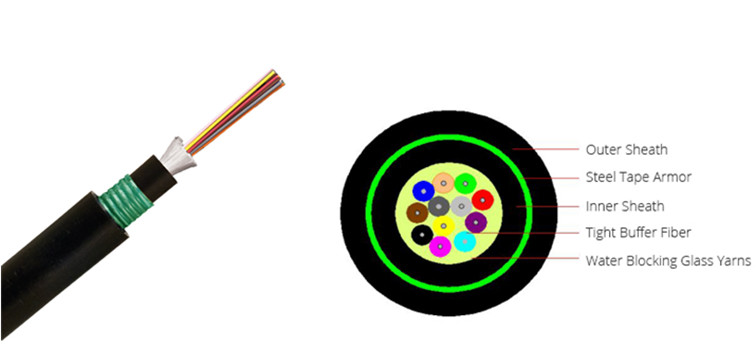
Armored tight buffered distribution fiber cable

Here we strongly recommend a low fiber count armored tight buffered distribution fiber cable which can be used for both indoor and outdoor applications (show in the above picture). This low fiber count armored tight buffered cable has a single-jacket design with a steel armored tape inside the cable. It can be used for both backbone cabling and horizontal cabling in indoor environments. And it can also be used for direct buried applications and aerial application in outdoor environments.

FS.COM Same Day Shipping Tight Buffered Distribution Fiber Cables Solution

During the purchasing of fiber optic cables, one of the most important thing is the shipment of fiber cables. Many bulk fiber cables are transmitted via shipping, which might take a long time. Now FS.COM customers in the USA can enjoy same day shipping for tight buffered distribution fiber cables for both indoor and outdoor applications. Details are shown in the following table. Kindly contact sales@fs.com for more details, if you are interested.
Part No. Description
31909 12 Fibers OM3 Plenum, FRP Strength Member, Non-unitized, Tight-Buffered Distribution Indoor Fiber Optical Cable GJPFJV
31922 12 Fibers OM4 Plenum, FRP Strength Member, Non-unitized, Tight-Buffered Distribution Indoor Fiber Optical Cable GJPFJV
31866 24 Fibers OM4 Riser, FRP Strength Member, Non-unitized, Tight-Buffered Distribution Indoor Fiber Optical Cable GJPFJV
51308 24 Fibers OS2, LSZH, Single-Armored Double-Jacket, Tight-Buffered Distribution Waterproof Indoor/Outdoor Cable GJFZY53

Related Article: Tight-Buffered Fiber Distribution Cable for Indoor and Outdoor Use

Difference Between 100G-QSFP-PSM4, 100G-QSFP-SR4 and 100G-QSFP-LR4

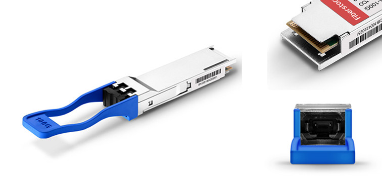
QSFP28 fiber optic transceiver is becoming the preferred solution for 100G network. It has the same outside looking as the 40G QSFP+ transceiver. But it has a 4*25G electrical interfaces which can transmit optical signals up to 100G. The part numbers of the QSFP28 transceivers are usually market as 100G-QSFP-xx. Now there is a wide selection of 100G QSFP28 modules for 100G Ethernet link, including fiber optic transceiver and direct attached cable. Different part numbers of 100G modules are making customers confused. This post will introduce the differences between the three 100G QSFP28 modules: 100G-QSFP-PSM4, 100G-QSFP-SR4 and 100G-QSFP-LR4.

100G QSFP

Transmission Mode

It is known that QSFP28 modules generally use four lanes to transmit 100G with each lane supporting 25G. Thus, the transmission method is just like 40G QSFP+ transceiver. 100G QSFP28 SR4, LR4 and PSM4 all use the 4*25 transmission mode. However, both the QSFP28 SR4 and QSFP28 PSM4 use a 12-fiber MTP interface which achieves dual-way 100G transmission over 8 fibers at the same time. QSFP28 LR4 uses a LC duplex fiber optic interface for 100G transmission on two directions at the same time. QSFP28 LR4 transmit optical signals over four different wavelengths around 1310nm with each wavelength carrying 25G optical signal. The wavelength ranges of the four lanes are as following:

  • 1294.53nm-1296.59nm
  • 1299.02nm-1301.09nm
  • 1303.54nm-1305.63nm
  • 1308.09nm-1310.19nm
Transmission Media and Distances

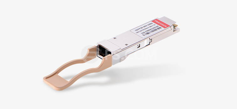
The three modules can support different transmission distances. 100G-SR4 QSFP28 module works over wavelength of 850nm and is used with 12-fiber MTP OM3 or OM4 multimode fiber cables for short transmission distances up to 100m. 100G-LR4 QSFP28 module is suggested to be used with single-mode fiber. It works over 1310nm wavelengths and can transmit 100G signals up to 2km. 100G-PSM4 QSFP28 is also used with 12-fiber MTP fiber cables but the fiber type is single-mode and the transmission distance is up to 500m.

100G-QSFP-SR4

Cabling Structure

The transmission mode of the fiber optic transceiver plays an important role during fiber cabling. 100G-QSFP-SR4 and 100G-QSFP-LR4 are invented for short distance transmission and long distance transmission separately. However, the have different cabling structure. The former requires a multi-fiber cabling structure based on 12-fiber MMF MTP interfaces. While 100G-QSFP-LR4 just required the traditional two-fiber SMF cabling structure. In this case, the conversion between multimode fiber to single-mode fiber would be complex as they used totally different cabling structure. Thus, 100G-QSFP-PSM4 is invented which runs over single-mode fiber, but uses the same cabling structure as 100G-QSFP-SR4. With 100G-QSFP-PSM4, the conversion between multimode and single-mode would save more without changing the existing fiber cabling structure.

100G QSFP28 Transceiver Data Rate Interface Fiber Type Transmission
Distance
Wavelengths Cabling Structure
100G-QSFP-SR4 4*25G MTP MMF 70m (OM3);
100m (OM4)
850nm 12-Fiber MTP
100G-QSFP-LR4 4*25G LC SMF 2km 1310nm LC Duplex
100G-QSFP-PSM4 4*25G MTP SMF 500m 1310nm 12-Fiber MTP
Conclusion

The above table listed the basic information of the three modules for your referent. 100G-QSFP-SR4 are suitable for short distance transmission over OM3 or OM4 fiber using 12-MTP fiber cabling system. 100G-QSFP-PSM4 also has a 12-fiber MTP interface but it can support a transmission distance up to 500m over SMF. 100G-QSFP-LR4 is suitable for long transmission distance up to 2km over two single-mode fibers.

Related Article: 40G vs 100G: Which One Is Worth the Investment?