Category Archives: How To

Factors to Consider Before DWDM Network Design

DWDM network deployment usually requires a lot of preparation. There are many factors to be considered before DWDM network design. Even a professional team would take a long time to calculate the parameters over and over to ensure good network performance, let alone some customers who are not experienced. In many cases, customers just have a rough concept of what they need for a DWDM network. When it comes to specific parameters of products, they get no idea. This post offers the most important factors to be considered before DWDM networking. No matter you want to deploy a DWDM network all by your own team, or you want to customize one by other vendors. You will find this post helpful.

DWDM Network Design

What Kind of DWDM Network You Want to Build?

This question contains many details. Here offer several basic factors:

Simplex or Duplex: it is known that DWDM network multiplex different wavelengths together to transmit different ways of optical signals over optical fiber. These wavelengths can be transmitted over the same optical fiber or a pair of optical fibers. Duplex DWDM uses the same for both transmitting and receiving for a way of duplex optical signal over duplex optical fiber. However, the simplex DWDM network uses two different wavelengths for a way of duplex optical signal over a length of single fiber. Thus, the simplex DWDM network provides lower capacity than duplex DWDM network.

Distance: DWDM network gets the greatest returns on investment. It is usually deployed for long distance transmission. But long distance means large light loss. Distance of DWDM network and devices or points it passes should also be considered.

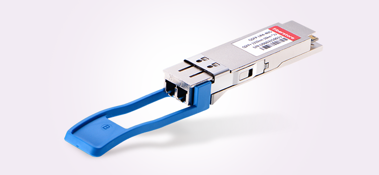
Data Rate and Space Channel: a DWDM network can transmit optical signals of different data rates at the same time. Currently, DWDM network generally transmits 1G and 10G for each wavelength. 1G DWDM SFP, 10G DWDM SFP+ and 10G DWDM XFP modules are usually used. Space Channel of 50 GHz Grid and 100 GHz Grid is commonly applied.

Is There Any Wavelength Adding and Dropping?

The DWDM network needs DWDM MUX/DEMUX for wavelengths multiplexing and de-multiplexing. It is common that a DWDM network passing many places. And wavelengths are required to be added and dropped at some of these places. In this case, DWDM OADM should be used.

DWDM MUX insertion loss test

How to Calculate Light Loss of DWDM Network?

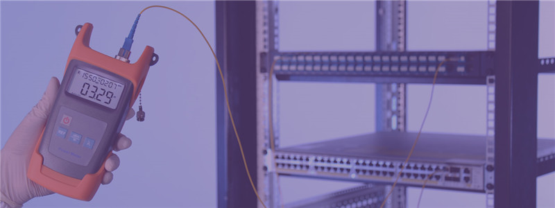
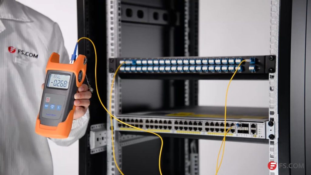
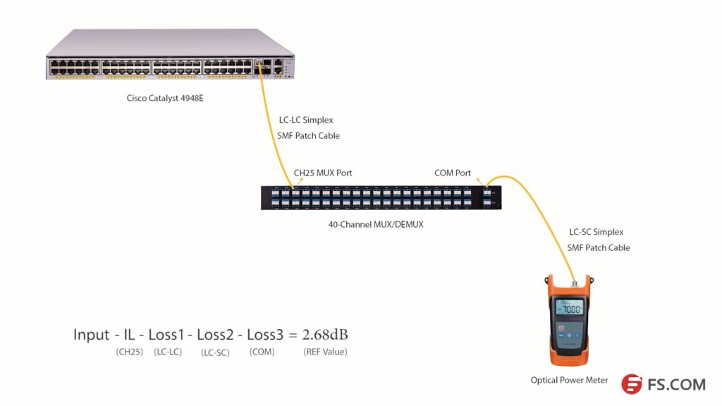
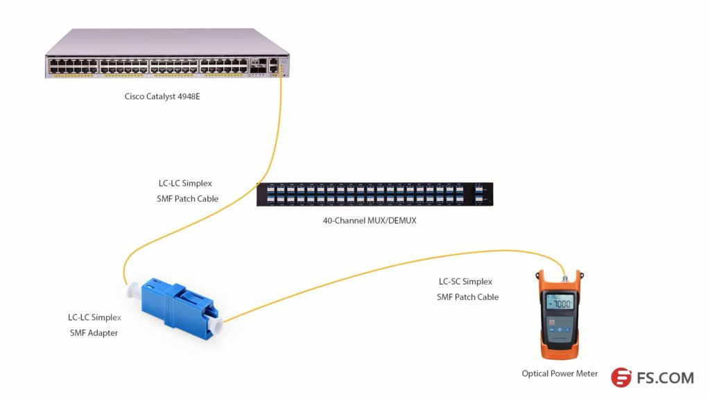
There is light loss in every DWDM network. Technicians should calculate the light loss to decide what devices to be added in the network to ensure good transmission quality. Light loss occurs at many place, the optical fiber for transmission, the DWDM MUX/DEMUX, the devices connected in the network and even the fiber optic splicers and connection points have light loss.

How to Ensure Good DWDM Network Transmission Quality?

There are a variety of factors that can affect the transmission quality. The light source, light loss, transmission distance, fault risks, etc. However, there are always methods to overcome problems. EDFA can be added in the network to ensure enough optical power. If optical power is too strong, fiber optic attenuator can be used. OEO offers conversion between grey wavelengths and DWDM wavelengths. DCM and OLP are separately used for light dispersion compensation and backup line building. These devices can be used properly for good transmission quality.

DWDM MUX

How to Satisfy the Requirements for Both Now and Future?

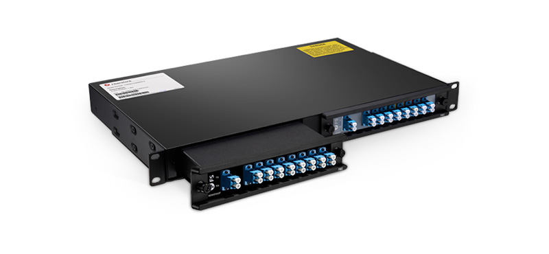
A DWDM network might only need to transmit several ways of optical signals. However, it might be required to transmission tens of ways optical signals. During the deployment, technician should considerate about the future application. If there is no limit in budget, it would be better to deploy DWDM MUX with more channel port. If not, you can try FS.COM FMU half-U plug-in DWDM MUX modules. You can buy one module for current use and expand the DWDM MUX with another module in the future easily via expansion port on the MUX. All the wavelengths on the DWDM MUX can be customized according to your application.

DWDM long haul

How to Get the Better Performance With Lowest Cost for DWDM Network?

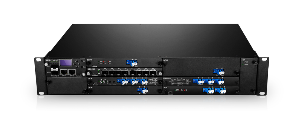
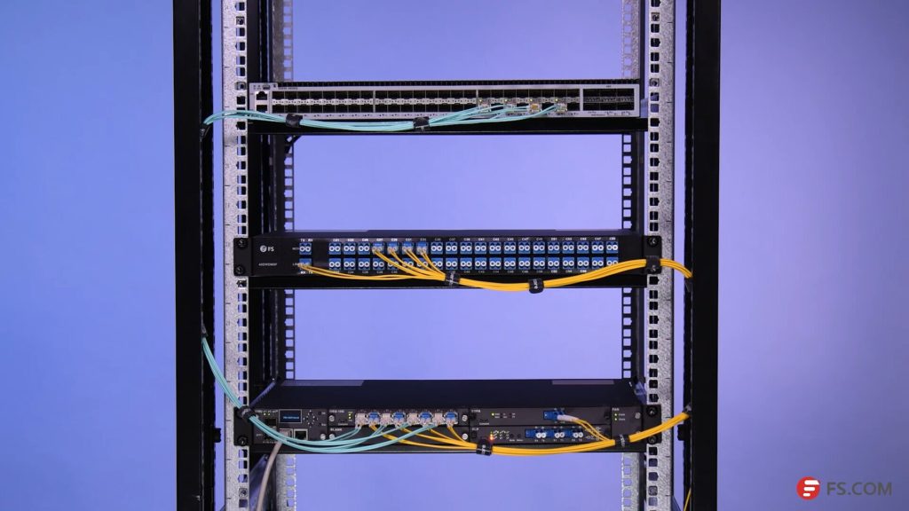
To get the better performance with lowest cost for DWDM network, you need carefully calculate the wavelength, light loss, devices and so on. In practical application, the DWDM network could be really complex, many devices like EDFA, OEO and DCM might be added in the network. It costs a lot for the deployment and management of these devices. Now FS.COM has made these devices into small plug-in cards and offers 1/2/4U chassis to hold them. A free software is also provided for better management and monitoring. This is FS.COM new series of product for DWDM long haul transmission—FMT multi-service transmission platform, which is a cost-effect and high performance system for DWDM network.

Professional Team for DWDM Network Design and Customization

The above mentioned factors are just the basic information that you should consider before DWDM network design. For more professional service and tech support, you can visit FS.COM where you can find professional DWDM network design and customized one-stop solution team and services.
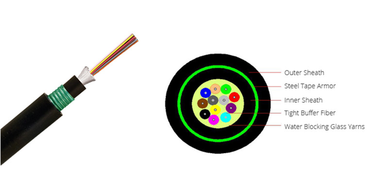
DWDM MUX/DEMUX Insertion Loss Test

During the selection of a DWDM MUX/DEMUX, the insertion loss should always be considered. Generally, a report including the insertion loss value of each port on the DWDM MUX/DEMUX, is usually attached with the product. These values are tested by professional testers. This post will illustrate how to test the insertion loss of DWDM MUX/DEMUX by using an easy-to-get optical power meter.DWDM MUX insertion loss test

Products Required for Insertion Loss Test

We will use Cisco Catalyst 4948E switch and Cisco compatible DWDM SFP+ modules as light source to test the insertion loss of a 40-CH DWDM MUX/DEMUX provided by FS.COM. This DWDM MUX/DEMUX has a typical insertion loss of 3.0 dB. Channel 25 port and Channel 60 port will be tested. The products and tools required are listed as following:

DWDM MUX/DEMUX Insertion Loss Test Steps

First, install the 80km C25 DWDM SFP+ module in the SFP+ port of Cisco Catalyst 4948E. Second, connect the Tx port of the SFP+ module to the Rx port of Channel 25 port with a length of LC-LC simplex single-mode patch cable. Then, connect the TX port of the COM port to the optical power meter with a length of LC-SC simplex single mode patch cable.

Please note to clean all the optical interfaces before connecting to ensure the accuracy of the testing result. The connection is shown in the following picture.

DWDM insertion loss test

Press the λ button to select the wavelength of 1550nm. Then, we will get the optical power value (2.68dB) of the signal from C25 80km DWDM SFP+ module. Light loss occurs when the optical signal pass LC-LC simplex SMF patch cable (Loss1), CH25 port, LC-SC simplex SMF patch cable (Loss2) and COM port (Loss 3) as shown in the above picture.

We get a simple formula here:

Input power – Insertion Loss (CH25) – Loss1-Loss2 -Loss3 = 2.68dB (REF value)

If we want to get the insertion loss value of Channel 25, the formula will be:

Insertion Loss (CH25) = Input power – Loss1 -Loss2 -Loss3 – 2.68dB (REF value)

We can set the 2.68dB as the reference value. And if we can test the optical power value of the channel 25 SFP+ after it experienced these three loss points, the difference value will be the insertion loss of the channel 25 channel port.

DWDM insertion loss test

As the com port could be regarded as an adapter, we will use an adapter to connect the LC-SC and LC-LC patch cables together. Then, connect them to the optical power meter as shown in the above picture, we can get the difference value which is 3.58dB. This value is the insertion loss of the Channel 25 port on this 40Ch DWDM MUX/DEMUX. This value might not be very accurate value, but it is close to it.

DWDM MUX/DEMUX Insertion Loss Testing Video


We have taken a video about how to test the 40CH DWDM MUX/DEMUX insertion loss with optical power meter. You can get more details in this video. All the products and tools in this video are provided by FS.COM. Kindly contact sales@fs.com or visit FS.COM for more if you are interested.

Cat5e Cable Structure and Cat5e Wiring Diagram

Network cables like Cat5, Cat5e and Cat6 are widely used in our network. Various Ethernet network cables are being invented. They can support different transmission distances and applications. Cat5e cables can support 1000base-T transmission up to 100 m, which meet the requirements of various applications in our home, office and data center. It has better performance than Cat5 and lower price than Cat6 making it a widely accepted type of Ethernet cable. This post introduces the details of Cat5e cable structure, Cat5e wiring, and wiring diagram.

Cat5e Wiring

Structure of Cat5e Cable

Cat5e uses four twisted pairs for transmission in each cable. The following picture shows the structure of the Cat5e cable. The termination of Cat5e Ethernet cable should use RJ45 connectors. As there are four pairs of copper wires inside a length of Cat5e cable, the cable pinouts should be carefully managed. For Cat5e, there are two commonly used methods for termination: straight-through and Crossover.

cat5e cable

Cat5e Wiring Diagram and Methods

Each pair of copper wires in the Cat5e has insulation with a specific color for easier identification. Cat5e wiring should follow the standard color code.

For the straight-through wiring method, there are two standards recognized by ANSI, TIA and EIA: T568A and T568B. Both of them can be used. However, the T568B is considered better than T568A wiring standard. The following picture shows, the wiring diagram of the two standards.

straight through cat5e

When you are doing the straight-through wiring, the cable pinout on the two ends of the Cat5e cable should be the same. However, for the crossover wiring method, the RJ45 pinouts on each end of the Cat5e are different. The following picture shows how the eight wires are used for transmission in a crossover terminated Cat5e cable.

Crossover cat5e

Actually, if you want to connect a T568A device with T568B device, you can use this crossover wiring method. The following picture shows the pinouts on each end of the Cat5e cable.

Crossover cat5e

How to Wire Cat5e Cables?

To terminate a Cat5e cable, you should prepare the cable. Here recommend a set of network installation tool kit which contains all you need to wire a category cable.

network installation tool kit

The following shows the process of how to terminate theEthernet cable:

cat5e wiring

Step 1, cut the cable to proper length and use the wire stripper to remove the outer jacket.

Step 2, untwist wires and trim the excess part. Flatten the wires out as much as possible, because they need to be very straight for proper insertion into the connector.

Step 3, hold the cable ends and place the wires in orders from left to right according to T568A or T568B wire scheme.

Step 4, insert the wires into the RJ45 connector. The wires must be sequenced in the same order of step 3.

Step 5, use the crimping tool to squeeze the plug. This ensures the firm connection between the cable and the plug.

Step 6, repeat the process on the opposite end and test the terminated cable to make sure communications between cable ends and the network is correct.

Cat5e Solution

The Cat5e has great advantages in various applications and there are many related products, like Cat5e patch cable, Cat5e bulk cable, Cat5e patch panel provided in the market. Kindly contact sales@fs.com for more details about Cat5e products, if you are interested.

Related Articles:
Quick View of Ethernet Cables Cat5, Cat5e And Cat6
Home Ethernet Wiring Guide: How to Get a Wired Home Network?
Patch Cable vs. Crossover Cable: What Is the Difference?

Which Tight Buffered Fiber Distribution Cable Fits Your Application?

Optical fibers with fiber counts ranging from 2 to 144 counts or more are usually coated together inside a single strand of fiber optic cable for better protection and cabling. Multi-fiber optic cables are usually required to pass a lot of distribution points. And each individual optical fiber should connect only one specific optical interface via splicing or terminating by connectors. Thus, fiber optic cables used for distribution should be durable and easy to be terminated. Tight buffered fiber distribution cables, which meet these demands, are widely used in today’s indoor and outdoor applications, like data center and FTTH projects. This post will introduce tight buffered fiber distribution cables.

tight buffered fiber cable

The Beauty of 900um Tight Buffered Fibers

Most of tight buffered fiber distribution cables are designed with 900um tight buffered fibers. This is decided by its applications. As the above mentioned, the distribution cable should be durable and easy to be terminated. The following picture shows the difference between 250um bare fiber and 900um tight buffered fiber. They are alike, but the tight buffered fiber has an additional buffer layer. Compared with bare fibers, 900um tight buffered fibers can provide better protection for the fiber cores. 900um tight buffered fibers are easy to be stripped for splicing and termination. In addition, tight buffered fiber cables are usually small in package and flexible during cabling. These are the main reasons why a lot of fiber optic distribution cables use tight buffered design.

250um vs 950um

Choose Tight Buffered Distribution Fiber Cables According to Applications

900nm tight buffered distribution fiber cables also come in a variety of types. Tight buffered distribution fiber cables used for different environments and applications might have different fiber types, outer jackets and cable structures. The following will introduce several tight buffered distribution fiber cables for your reference.

unitized distribution fiber cable
Indoor Tight Buffered Distribution Fiber Cable

Tight buffered distribution fiber cables used for indoor applications are usually used for intra building backbones and routing between telecommunication rooms. Large tight buffered fiber cable with fiber counts more than 36 fibers generally has “sub-unit” (unitized) design (shown in the above). While smaller tight buffered distribution cables, with fiber counts of 6, 12 or 24, usually have “single-jacket” (non-unitized) designs, which are more flexible in cabling and have much smaller packages and cost advantages. The lower count tight buffered distribution fiber cables with color coded 12 fibers and 24 fibers are very popular. The following picture shows a 24-fiber indoor tight buffered distribution fiber cable with single-jacket design.

24-fiber tight buffered fiber cable

During practical use, these 6, 12 or 24-fiber indoor tight buffered distribution fiber cables can be spliced with other fibers or be terminated with fiber optic connectors. And they can be made into multi-fiber optic pigtails or fiber patch cable after terminated with fiber optic connector on one end or two end. The color coded fibers can also ease fiber cabling.

Indoor/Outdoor Armored Tight Buffered Distribtight buffered fiber terminationution Fiber Cable

Although tight buffered distribution fiber cables are usually used for indoor applications, there is still a place for them in outdoor applications after added with a layer of metal armored tube inside the cable. Armored fiber cables are durable, rodent-proof, water proof and can be directly buried underground during installation, which saves a lot of time and money.

Armored tight buffered distribution fiber cable

Here we strongly recommend a low fiber count armored tight buffered distribution fiber cable which can be used for both indoor and outdoor applications (show in the above picture). This low fiber count armored tight buffered cable has a single-jacket design with a steel armored tape inside the cable. It can be used for both backbone cabling and horizontal cabling in indoor environments. And it can also be used for direct buried applications and aerial application in outdoor environments.

FS.COM Same Day Shipping Tight Buffered Distribution Fiber Cables Solution

During the purchasing of fiber optic cables, one of the most important thing is the shipment of fiber cables. Many bulk fiber cables are transmitted via shipping, which might take a long time. Now FS.COM customers in the USA can enjoy same day shipping for tight buffered distribution fiber cables for both indoor and outdoor applications. Details are shown in the following table. Kindly contact sales@fs.com for more details, if you are interested.

Part No. Description
31909 12 Fibers OM3 Plenum, FRP Strength Member, Non-unitized, Tight-Buffered Distribution Indoor Fiber Optical Cable GJPFJV
31922 12 Fibers OM4 Plenum, FRP Strength Member, Non-unitized, Tight-Buffered Distribution Indoor Fiber Optical Cable GJPFJV
31866 24 Fibers OM4 Riser, FRP Strength Member, Non-unitized, Tight-Buffered Distribution Indoor Fiber Optical Cable GJPFJV
51308 24 Fibers OS2, LSZH, Single-Armored Double-Jacket, Tight-Buffered Distribution Waterproof Indoor/Outdoor Cable GJFZY53

Related Article: Tight-Buffered Fiber Distribution Cable for Indoor and Outdoor Use

Cisco S-Class vs Non-S-Class Module

Cisco switches and fiber optic transceivers are considered as the benchmarks of the market with a market share more than 50%. With the development of fiber optic network, Cisco has developed a variety of fiber optic transceivers for different applications and has built a system to name each transceiver. For instance, the most commonly used 10G Cisco modules like SFP-10G-SR and SFP-10G-LR have part numbers which can accurately descript their biggest features. SR means “short range” and LR means “long range”. However, customers find the part numbers of some Cisco modules are named with an “S”, like SFP-10G-SR-S and SFP-10G-LR-S. Cisco calls them S-class modules. People might get confused by these Cisco S-class modules. Cisco S-Class vs Non-S-Class module, or SFP 10G SR S vs SFP 10G SR, which one should you choose?

sfp 10g sr s vs sfp 10g sr

Cisco S-Class Module VS Cisco Non-S-Class Module

Cisco only published four 10G S-class SFP+ modules and two 40G S-class QSFP+ modules. The following table listed Cisco S-class modules. Cisco S-class modules seem to have no differences from the non-S-class modules. However, if you read the specification of these modules and the suggestions from Cisco, you will find the differences.

Data Rate S-Class Module Non-S-Class Module Media
10G SFP-10G-SR-S SFP-10G-SR MMF (duplex)
10G SFP-10G-LR-S SFP-10G-LR SMF (duplex)
10G SFP-10G-ER-S SFP-10G-ER SMF (duplex)
10G SFP-10G-ZR-S SFP-10G-ZR SMF (duplex)
40G QSFP-40G-SR4-S QSFP-40G-SR4 MMF (ribbon)
40G QSFP-40G-LR4-S QSFP-40G-LR4 SMF (duplex)

Protocol

The standard non-S-class Cisco modules like SFP-10G-SR and SFP-10G-LR can support three protocols including Ethernet, OTN (Optical Transport Network) and WAN-PHY (Wide Area Network Physics). However, the S-class modules can only support Ethernet protocol.

Temperature Range

Compared with Cisco C-class modules which can be operating with three different temperature ranges, the Cisco S-class modules can only support the commercial temperature ranges which is 0 to 70°C (32 to 158°F).

  • Commercial temperature range (COM): 0 to 70°C (32 to 158°F)
  • Extended temperature range (EXT): -5 to 85°C (23 to 185°F)
  • Industrial temperature range (IND): -40 to 85°C (-40 to 185°F)

Transmission Distance

Cisco has introduced that the S-class modules are suggested to be used in enterprise network. In addition, the operating temperature range is smaller, thus, S-class module is recommended for shorter transmission distance applications compared with other standard modules.

Price

As the performance of Cisco S-class modules are no better than other modules, why did Cisco published these modules? This is because Cisco S-class modules have lower prices, which is also their biggest sale point.

cisco s-class module

Should I Choose Cisco S-Class Module?

In conclusion, S-class can only support Ethernet protocol and has a commercial temperature range, which is suggested to be used in applications that no special long distance, temperature tolerances, or other special features are required. But many people might not select S-class modules, considering about the future use. As Cisco original branded transceivers are expensive, many people will use third party modules which are much cheaper but is compatible with Cisco devices. A Cisco compatible non-S-class module could be much cheaper than a Cisco original brand S-module. But it can provide almost the same performance as the Cisco original branded non-S-class module.

Related Article: Cisco SFP-10G-SR: All You Need to Know

A Comprehensively Understanding of Cisco 10GBASE SFP+ Modules