
HFC/CATV Network Overview
CATV, which originally called community antenna television is much more often called “cable TV” for people. As the rapid growth of the amount of residential Internet users and the increased bandwidth requirements of multimedia applications have necessitated the development of an access network that can support the need for such services.HFC/CATV networks appear to be within an important position for supporting these types of services.
An HFC/CATV network typically uses coaxial cable for short runs between peripheral equipment and also the transmitter or cable receiver at the user end. At the same time, optical transmission links between headends use singlemode fiber to greatly extend the transmission distance. This combination permits the system designer to maximise costeffectiveness when choosing the system components.
HFC/CATV network develops in an evolutionary manner. A one-way, broadcast analog video service just by replacing the trunk coax cable with fiber is first appeard. Optical transmitters are placed in the headend and the fiber is terminated with optical nodes. The optical nodes are temperature hardened, environmentally sealed containers capable of being placed underground or hung off poles. The optical nodes can transport a slew of modules for example optical receivers to convert the optical signal to an electrical format for distribution within the coax network. The next phase ended up being to upgrade the plant to supply two-way services. The unused 5 to 42 MHz spectrum can be used for upstream communication for example cable modem data. Upgrading to two-way involves having two-way amplifiers and putting optical transmitters within the optical nodes so as to transport the return signals in the customer premises to the headend. At the headend an optical receiver is required for every return fiber in the node. Adding two-way capability to the plant permits the cable operator to provide video, voice and knowledge.
How to build a HFC/CATV Network?
A traditional HFC/CATV distribution system includes 3 layers:
First, supertrunks carry signals over long distances. Distances of 100 km might be achieved rich in signal fidelity, having a single fiber link; Second, feeder links typically span a shorter distance and fasten a fiber hub (supertrunk termination) to a fiber node. Nodes are the reason for a network at which fiber is converted back to RF – this amplified RF is usually fed over coaxial cable to some number of CATV set top boxes. The feeder link inside an HFC system is roughly equal to the sort of link that the business or campus would use to extend CATV coverage over a distance that’s more than is possible with high fidelity over coaxia cable; Third, a drop is usually a link connecting one tuner. If distance is prohibitive of coaxial cable, this link may also be implemented with fiberoptics.
HFC/CATV Networks building cases
Small Private HFC/CATV Networks (Figure 1.)
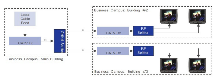 Figure 1. Small Private HFC/CATV Networks
Small to Medium Size Private HFC/CATV Networks (Figure 2.)
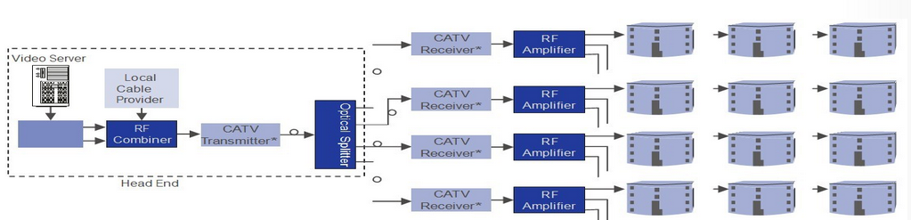
Figure 2. Small to Medium Size Private HFC/CATV Networks
Large Scale Campus and Municipal Networks (Figure 3.)
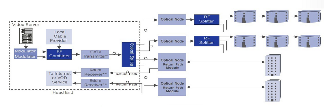 Figure 3. Large Scale Campus and Municipal Networks
Why choose Fiberstore for your HFC/CATV network building solution?
Fiberstore is a professional optical products company. As the HFC/CATV network develops very rapidly, the high demands of HFC optic fiber products is urging the devices providers to improve themselves. Fiberstore has specialized in the development and improvement of HFC optic fiber products for HFC/CATV network, especially the optical transmitters (see the Figure 4.)
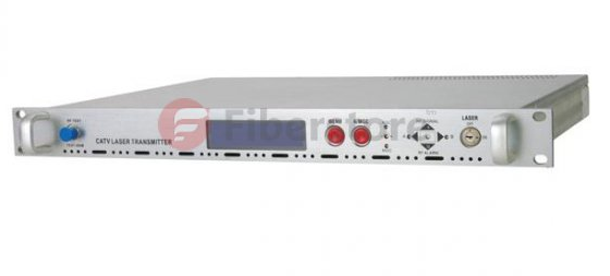
Figure 4. Fiberstore optical transmitters
Advantages of Fiberstore Optical Transmitters:
Pre-distortion circuit makes product have excellent non-linear index, ensure optical fiber network and long-distance transmitting, make out users cover.
Microprocessor circuit and VFD, for control and display optical transmitter work status and parameter.
Perfect Laser control and protect circuit, ensure the stable reliable work capability
Fiberstore Optical Transmitters Applications:
1310 broadcast and narrow cast applications
CATV forward path
RF over fiber
There are more products of CATV optical Transmission which will help you make your item works perfectly, know more, click here!