Category Archives: Uncategorized

What Is Data Center Architecture?

What Is Data Center Architecture?

A data center is a physical facility that supports an enterprise’s computing activities, which realizes centralized processing, storage, transmission, exchange, and management of information. Data center architecture, as an architectural design that establishes connections between switches and servers, is typically created during the data center design and construction phases. Besides, it designates the way that the server, storage networking, racks, and other data center resources will be placed and also addresses the interconnection of these devices.

Types of Data Center Architecture

Typically, there are four kinds of data center architecture: mesh work, three-tier or multi-tier model, mesh point of delivery (PoD), and super spine mesh.

Mesh Network

The mesh network architecture, a kind of data center architecture, usually regarded as the network fabric, describes the network topology in which components pass data to each other through interconnecting switches. With predictable capacity and lower latency, it can support common cloud services. Besides, because of its distributed network designs, the mesh network can easily realize any connection and be more cost-effective in terms of network deployment.mesh network

Three-tier or Multi-tier Model

The multi-tier architecture has been the most commonly deployed model of data center architecture used in the enterprise data center, consisting of core, aggregation, and access layers.

  • Data center core layer: It provides a fabric for high-speed packet switching between multiple aggregation modules and connectivity to multiple aggregation modules.
  • Data center aggregation layer: It supports functions like service module integration, layer 2 domain definitions, spanning tree processing, and default gateway redundancy.
  • Data center access layer: It provides the physical level attachment to the server resources and operates in layer 2 or layer 3 modes. What’s more, it plays an important role in meeting particular server requirements such as NIC teaming, clustering, and broadcast containment.multi-tier model

Mesh Point of Delivery

The mesh point of delivery (PoD) architecture contains multiple leaf switches interconnected within the PoDs. It is a repeatable design pattern and its components maximize the modularity, scalability, and manageability of data centers. Besides, this architecture can realize the efficient connection between multiple PoDs and a super-spine tier. Therefore, data center managers can add new data center architecture to their existing three-tier topology easily for the low-latency data flow of new cloud applications.mesh point of delivery

Super Spine Mesh

Just as its name shows, super spine architecture is suitable for large-scale or campus-style data centers. This type of data center architecture services huge amounts of data passing from east to west through data halls.super spine mesh

Typical Composition of Data Center Architecture

The data center has plenty of functions and supports different types of services, such as data computing, storage, processing, etc, resulting in a variety of data center architecture.

The data center architecture mainly consists of three parts: data center network, security, and computing architecture. Apart from these three, there are some other data center architectures, such as data center physical architecture and data center information architecture. The following will mainly interpret three typical compositions of it.

Data Center Network Architecture

Data Center Network (DCN) is an arrangement of network devices that interconnect all data center resources together, which has always been a key research area for Internet companies and large cloud computing companies. Therefore, data center network architecture plays a vital role in data center architecture.

It usually consists of switches and routers in a two- or three-level hierarchy. For example, three-tier DCN, fat tree DCN, DCell, and other types. Besides, the scale, scalability, robustness, and reliability of the data center network architecture have always been the focus of attention.

Data Center Security Architecture

Data center security refers to the physical practices and virtual technologies for protecting data centers from threats, attacks, and unauthorized access. Lack of efficient data center security protections may result in data breaches, where a company’s information may get attacked by hackers.

Data center security architecture mainly includes two aspects: physical security and software security. Enterprises can protect data centers from attack by setting up a strong firewall between the external traffic and the internal network.

Data Center Computing Architecture

In the data center computing model, computer resources can be moved to the edge where the data resides, thus reducing the latency and bandwidth issues in transmission.

Data center computing architecture is one of the most important parts of data center architecture, which plays a huge role in the high-efficient use of resources, reducing capital expenditure (CAPEX) costs, and rapid deployment and scalability.

Data Center Architecture Evolution

With the continuous development of technology, the evolution of data center architecture is ongoing. Most modern data center architecture has evolved from on-premises physical servers to virtualized infrastructure that supports networks, applications, and workloads in multiple private and public clouds. This evolution has affected the way data centers are architected because all components of a data center may only access each other via the public Internet.

Article Source: What Is Data Center Architecture? | FS Community

Related Articles:

Infographic – What Is a Data Center? | FS Community

What Are Data Center Tiers? | FS Community

What Is a Data Center? | FS Community
SFP Connector vs SFP+ Connector vs SFP28 Connector

SFP (Small Form-factor Pluggable) module connector with various data speed rate is one of the major optical transceivers used for data communication. With ever-increasing demand for faster speed and higher density, the SFP connectors have experienced several generations of update for the signal speed capability as well as port density, from the original SFP to SFP+ and then to the new SFP28 type. The compatibility of these connecting ports is the pain point for many subscribers in data communication transmission. So what’s the similarities and differences between them and are these module connectors compatible with each other when plugged into switches? SFP28 vs SFP+ vs SFP connector, which one should you choose? This paper will give you the answer.

What Is SFP Connector?

Specified by a multi-source agreement (MSA), SFP connector was first introduced in early 2000 and designed to replace the previous gigabit interface converter (GBIC) connector in fiber optic and Ethernet high-speed networking systems. Based on the IEEE 802.3, SFF-8472 protocol specification, SFP module connectors has the ability to handle up to 4.25Gb/s with greater port density than the GBIC, which is why SFP is also known as mini GBIC. This allowed it to quickly become the connector of choice for system administrators who liked the idea of being able to significantly increase their output per rack. The SFP connectors can support Gigabit Ethernet, Fibre Channel, Synchronous Optical Network (SONET) and other communication standards.

What Is SFP+ Connector?

To cater the need for faster transmission speed, the SFP+ (or SFP10) was introduced in 2006, as an extension of the SFP connector. Based on IEEE802.3ae, SFF-8431, and SFF-8432 protocol specifications, the SFP+ is designed to support data rates up to 10Gb/s. Compared with its predecessor SFP, the newly SFP+ can support Fibre Channel, 10GbE, SONET, OTN, and other communication standards. The SFP+ is similar in size to the SFP connector. And the primary difference between an SFP and a SFP+ is their transmission speed. It is noticeable that SFP/SFP+ are both copper and optical.

SFP28

SFP28 Connector–The Third Generation of SFP Connector

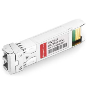
As the third generation of SFP interconnect systems, the SFP28 (Small Form-Factor Pluggable 28) is designed for 25G performance specified by the IEEE 802.3by. The SFP28 connector delivers increased bandwidth, superior impedance control with less crosstalk compared to the SFP10. SFP28 can be sorted into SFP28 SFP-25G-SR and SFP-25G-LR. The former is designed to transfer data over short distance (up to 100m over MMF) while the latter is suitable for long distance transmission (up to 10 km over SMF). Utilizing 25GbE SFP28 leads to a single-lane connection similar to existing 10GbE technology, however it can deliver 2.5 times more data, which enables network bandwidth to be cost-effectively scaled in support of next-generation server and storage solutions.

Are the SFP, SFP+ and SFP28 Products Backward Compatible?

In most cases the connector and cable assembly are all backward compatible – an SFP+ connector is a direct replacement for an SFP connector to ensure simple upgrade to customer systems. As these are standard products, the cable assembly will also be compatible between the systems – an SFP copper cable assembly can be inserted to an SFP+ cage and mate with a SFP+ connector on the board.

Then how about the new SFP28 product? Since transceivers with various SFP connector types have become an important constituent of data communication network, compatibility issue of SFP28 and SFP+ is controversial among many subscribers. Here is a typical topic from Reddit, and it says like “For a project we’re looking to purchase some nexus 93180YC-EX ToRs for 25Gb+ down to the compute nodes. Cisco states that the downlink 25Gb ports are also 10Gb capable, but one can only really assume that means that the port is compatible with SFP+ optics too. Cisco’s SFP+ compatibility matrix appears to support that claim, however just curious if any of you have any SFP28 experience yet to confirm?”

The answer is definitely “yes”. SFP28 adopts the same form factor as SFP+, just running at 25 Gb/s instead of 10Gb/s, which offers better performance and higher speed. Besides, the pinouts of SFP28 and SFP+ connectors are mating compatible. Therefore, SFP28 connector is backwards compatible with SFP+ ports. That is to say, an SFP28 can be plugged into an SFP+ port and vice versa, but plugging an SFP+ into an SFP28 port would not get you 25Gb/s data rates.

Conclusion

SFP28 vs SFP+ vs SFP connector? Have you made clear which one to choose? Whether choosing SFP or SFP+ depends on your switch types. If your switch port only supports 1G, you can only choose the 1000BASE SFP (eg.MGBSX1). If it is a 10G switch, it depends on the speed and distance you require. When choosing between SFP28 and SFP+, it all depends on the transmission data rates you need. The SFP28 aims to build 25GbE networks that enables equipment designers to significantly reduce the required number of switches and cables. Thus when considering reduced facility costs related to space, power and cooling, the SFP28 would be the optimal choice for you.

Related articles: FS.COM QSFP28 Optical Modules Solution

                             SFP Compatibility Guide and How to Use a Compatible SFP Module?

How to Build DWDM Network Over CWDM Network

Using CWDM MUX/DEMUX has been widely accepted as the most cost-effective and time-save method to increase the existing fiber optic network without adding optical fibers. However, a CWDM network can only support up to 18 different wavelengths. Is there any possibility to increase the capacity of the existing CWDM network? Hybrid CWDM and DWDM network is being introduced to combine the DWDM wavelengths with the existing CWDM wavelengths.

Combing DWDM With CWDM to Increase Network Capacity

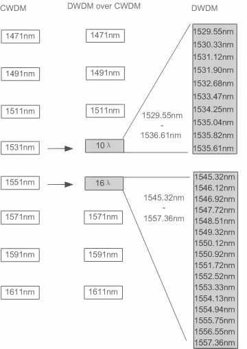
As we know the CWDM wavelengths ranging from 1260nm-1625nm with space channel of 20nm actually cover all the range of DWDM wavelengths (ranging from 1470nm to 1625nm). However, DWDM wavelengths have much smaller channel spaces (0.4nm/0.8nm/1.6nm) and can provide larger bandwidth than that of the CWDM wavelengths. To combine DWDM with CWDM, the CWDM wavelengths that are near DWDM wavelengths can be used to transmit the DWDM wavelengths. However, not all these CWDM wavelengths are suggested. Generally, wavelengths of 1530nm and 1550nm are used to combine the CWDM and DWDM network together. Similarly, not all the DWDM wavelengths are suggested to be combined with CWDM network. The following picture shows DWDM wavelengths that are suggested to be combined with 1530nm and 1550nm.

CWDM DWDM hybrid wavelengths

How to connect CWDM With DWDM

To combine the DWDM wavelengths with CWDM wavelengths, both CWDM MUX/DEMUX and DWDM MUX/DEMUXs should be used. The following picture shows the connection methods for hybrid CWDM and DWDM. On both ends of the fiber link, a CWDM MUX/DEMUX and a DWDM MUX/DEMUX with corresponding wavelengths are deployed. Connect the line port of the DWDM MUX/DEMUX to the 1530nm/1550nm channel port of the CWDM MUX/DEMUX, the DWDM wavelengths can be added to the existing CWDM network.

DWDM over CWDM

Easier Operation and Cabling Solution for Hybrid CWDM and DWDM

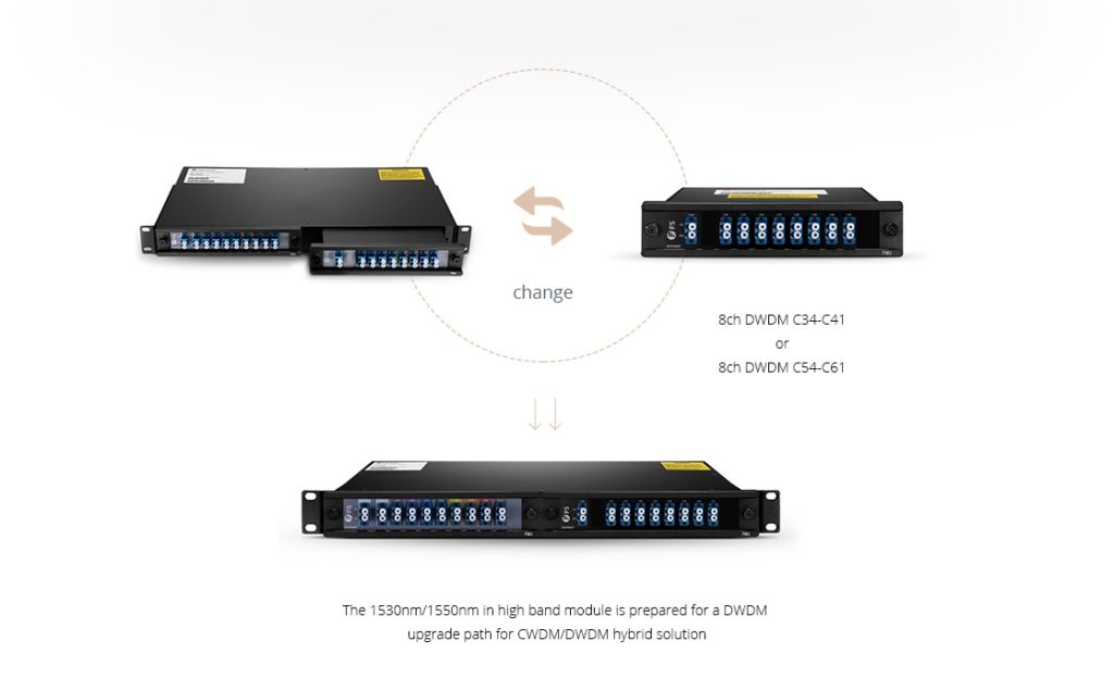
In the CWDM and DWDM Hybrid network, the CWDM MUX/DEMUX and DWDM MUX/DEMUX play the most important roles. To offer better operation and cabling environment for these WDM MUX/DEMUX, FMU series products which are developed by FS.COM has been introduced. This series of products combines the MUX/DEMUX into half-U plug-in modules, and installed in 1U rack for better cable management and network operation as shown in the following picture.

FMU DWDM over CWDM solution

For CWDM and DWDM hybrid network, a FMU CWDM MUX/DEMUX and a DWDM half-U plug-in module can be installed together in a FMU 1U rack chassis. Thus, the two modules can be linked together easily. Meanwhile, with clear port identification, the management and operation of the fiber optic network would be easier.

Conclusion

The CWDM network can be added with DWDM wavelengths by the using of CWDM MUX/DEMUX and DWDM MUX/DEMUX which support corresponding wavelengths. The DWDM wavelengths that are 6.5nm around 1530nm and 1550nm are suggested to be used for CWDM and DWDM hybrid network. For better network operation and cabling, FMU series WDM solutions are suggested, which can provide easier and more flexible connections between CWDM MUX/DEMUX and DWDM MUX/DEMUX. Kindly contact sales@fs.com for more details about DWDM over CWDM solution, if you are interested.

Source: How to Achieve DWDM Over CWDM

What 2016 Optical Interconnection Hardware Market Will Be Like?

2016 optical interconnection hardware market trend

2015 is a harvest year to many vendors in optical communication. According to the research “Optical Network Hardware Tracker” by IHS, the global optical network market has increased 3 percent to $ 12.5 billion in 2015. Even, optical interconnection hardware market, which usually has the most fierce competition, also increased in 2015 driven by the whole industry. Will this tendency be kept in 2016 for optical interconnection hardware market?

Needs Drive the Market

Firstly, the insight of optical interconnection hardware market in last year should be given. In 2015, optical growth is greatly driven by the increasing needs for higher Ethernet speed. This is because the application of advanced technologies like Cloud, Internet of Things, and virtual data center. In addition, the deployment of projects like FTTH (fiber to the home) and 4G network also promoted the optical interconnection hardware market. It is clear that these applications and projects will still be the largest driver of the optical interconnect market in 2016. The most possible trends of optical interconnection hardware market could be concluded by three keywords: high speed, compatible and high density.

High Speed—Breakout Year of 100G

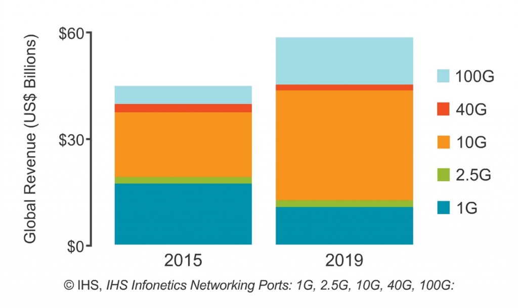
High speed is one of the keywords of this industry, and for 2016, it still plays an important role. It is clearly proved by the market needs that higher Ethernet speed is the irresistible trend. Although not many data centers have taken the lead to migration to 40/100G, the 40G and 100G will be the key growth segment of the market in the next few years according to the research by IHS. As shown in the following picture, the 100G market is predicted to grow 262 percent from 2015 to 2016. Inspecting the 2015 market signals, 2016 might be the breakout year of 100G. Fiberstore as the leading provider in optical communication has already launched 100G interconnection products including 100G transceiver and DAC (direct attached cable).

IHS global network market prediction

Compatible—More Economical Choices for Customers

An important reason why so many data centers and enterprise networks slow down the 40/100G migration plan, is the cost. For example, almost every data center needs optical transceivers and DAC for interconnection. And these products must be compatible from the switches. However, the switch market has already been monopolized by large vendors like Cisco. And the original brand 100G optical transceivers and DACs are usually very expensive. Luckily, vendors like Fiberstore can provide full series optical transceivers with a lifetime warranty, fully compatible with networking kit. What’s more these products are much cheaper than the original brand ones and have the same performance. These third party transceivers offer customers more choices with lower prices, which is very likely to promote the optical interconnection market, especially, for 100G products.

High Density—Urgent Problem

High Ethernet speed means more devices and cables should be deployed in data center where the space is usually limited. Enlarging the size of a data center is a good method, however, it will cost a lot. Except the investment for more room, the invest for maintenance and cooling also cannot be ignored. Thus, increasing the port and cabling density would be the most economical and effective way for most data centers. In the past years, small form factor optics, high density network rack system and MPO products are applied to increase the cabling and port density. In 2016, Fiberstore innovatively provides high density LC and MPO patch cords with push-pull tabs which can increase the cabling density and flexibility effectively for optical interconnection.

Facing the Competition

High speed, compatible, and high density three most obvious trends of 2016 optical interconnection hardware market. With the driver of the market needs, the market is very likely to keep the tendency of 2015. Growth of 100G interconnection products is predicted to be a key growth segment in 2016. However, where there is market there is competition. Seen the market signals, more vendors will join the competition of optical interconnection hardware market. By providing fully tested products and the most reasonable price of optical interconnection products, Fiberstore is ready and willing to face the challenges and opportunities in 2016.

Migrating to 40/100G With OM3/OM4 Fiber

To meet the continuously increased requirements, data center 40/100G migration is underway. The infrastructure of data centers for the 40G/100G should meet the requirements like high speed, reliability, manageability and flexibility. To meet these requirements, product solutions and the infrastructure topology including cabling must be considered in unison. Cable deployment in the data center plays an important part. The cable used in data center must be selected to provide support for data rate applications not only of today but also the future. Today, two types of multimode fiber—OM3 and OM4 fibers (usually with aqua color)—have gradually become the media choice of data center during 40/100G migration. This article illustrates OM3/OM4 multimode fibers in 40/100G migration in details.

Data Center and Multimode Fibers

Multimode fiber is being widely used in data centers. You might ask why not single-mode fiber? The answer is cost. As is known to all, the price of single-mode fiber is generally more expensive than multimode fiber. In addition multimode fibers provide a significant value proposition when compared to single-mode fiber, as multimode fiber utilizes low cost 850 nm transceivers for serial and parallel transmission. If you had all money you wanted and you’d just run single-mode fiber which has all the bandwidth you need, then you can go plenty of distance. However, this perfect situation would cost a lot of money. Thus, most data center would choose multimode fiber. OM1, OM2, OM3 and OM4 are the most popular multimode fiber. But OM3 and OM4 are gradually taking place of OM1 and OM2 in data centers.

OM

OM stands for optical multimode. OM3 and OM4 are both laser-optimized multimode fibers with 50/125 core, which are designed for use with 850nm VCSELS (vertical-cavity surface-emitting laser) and are developed to accommodate faster networks such as 10, 40 and 100 Gbps. Compared with OM1 (62.5/125 core) and OM2 (50/125 core), OM3 and OM4 can transport data at higher rate and longer distance. The following statistics (850 nm Ethernet Distance) shows the main differences between these four types multimode fibers, which can explain why OM3 and OM4 is more popular in data center now in some extent.

850 nm Ethernet Distance
Fiber Type 1G 10G 40/100G
OM1 300 m 36 m N/A
OM2 500 m 86 m N/A
OM3 1 km 300 m 100 m
OM4 1 km 550 m 150 m


Why Use OM3 and OM4 in 40/100G Migration

The Institute of Electrical and Electronics Engineers (IEEE) 802.3ba 40/100G Ethernet Standard was ratified in June 2010. The standard provides specific guidance for 40/100G transmission with multimode and single-mode fibers. OM3 and OM4 are the only multimode fibers included in the standard. The reason why OM3 and OM4 are applied in 40/100G migration is that they can meet the requirements for the migration cabling performance.

Bandwidth, total connector insertion loss and transmission distance are two three main factors should be considered when evaluation the performance needed for cabling infrastructure to meet the requirements for 40/100G. These factors can impact the cabling infrastructure’s ability to meet the standard’s distance of at least 100 meters over OM3 fiber and 150 meters over OM4 fiber. The following explains why OM3/OM4 are the chosen ones for 40/100G migration.

Get Higher Bandwidth With OM3/OM4

Bandwidth is the first reason why OM3 and OM4 are used for 40/100G migration. OM3 and OM4 are optimized for 850nm transmission and have a minimum 2000 MHz∙km and 4700 MHz∙km effective modal bandwidth (EMB). Comparing the OM1 and OM2 with a maximum 500 MHz∙km, advantages of OM3 and OM4 are obvious. With a connectivity solution using OM3 and OM4 fibers that have been measured using the minimum Effective Modal Bandwidth calculate technique, the optical infrastructure deployed in the data center will meet the performance criteria set forth by IEEE for bandwidth.

Get Longer Transmission Distance With OM3/OM4

The transmission distance of fiber optic cables will influence the data center cabling. The manageability and flexibility will be increased with fiber optic cables with longer transmission distance. OM3 fiber and OM4 fiber can support longer transmission distance compare with other traditional multimode fibers. Generally OM3 fibers can run 40/100 Gigabit at 100 meters and OM4 fibers can run 40/100 Gigabit at 150 meters. This high data rate and longer distance cannot be achieved by other traditional multimode fiber like OM1 and OM2. Employing OM3 fiber and OM4 in 40/100G migration is required.

Get Lower Insertion Loss With OM3/OM4

Insertion loss has always been an import factor that technically should consider during the data center cabling. This is because the total connector loss within a system channel impacts the ability to operate over the maximum supportable distance for a given data rate. As total connector loss increased, the supportable distance at that data rate decreases. According to the 40/100G standard, OM3 fiber is specified to a 100m distance with a maximum channel loss of 1.9dB, which includes a 1.5dB total connector loss budget. And OM4 fiber is specified to a 150m distance with a maximum channel loss of 1.5 dB, including a total connector loss budget of 1.0 dB. With low-loss OM3 and OM4 fiber, maximum flexibility can be achieved with the ability to introduce multiple connector mating into the connectivity link and longer supportable transmission distance can be reached.

OM3 or OM4?

Choosing OM3/OM4 is a wise and required choice for data center 40/100G migration. However, OM3 and OM4, which is better? Numerous factors can affect the choice. However, the applications and the total costs are always the main factors to consider to figure out whether OM3 or OM4 is needed.

First, the connectors and the termination of the connectors for OM3 and OM4 fibers are the same. OM3 is fully compatible with OM4. The difference is just in the construction of fiber cable, which makes OM4 cable has better attenuation and can operate higher bandwidth at a longer distance than OM3. Thus, the cost for OM4 fiber is higher than OM3. As 90 percent of all data centers have their runs under 100 meters, choosing OM3 comes down to a costing issue. However, looking in the future, as the demand increases, the cost will come down. Thus, OM4 might be the most viable product at some point soon.

No matter choosing OM3 or OM4, the migration is underway. With good performance like high data rate, long transmission distance and lower inserting loss, OM3/OM4 fiber is a must in data center migration to 40/100G.

Source: http://www.fs.com/blog/om3-and-om4-in-40-100g-migration.html