Tag Archives: DWDM MUX

DWDM Network over Long Distance Transmission

With the ever-increasing need for higher bandwidth, DWDM technology has been one of the most favorable optical transport network (OTN) applications. In this post, we will reveal FS.COM DWDM-based network solutions over various transmitting distances as well as some suggestions for the DWDM networks deployment.

DWDM Networks Basics

As usual, let’s review some basics of DWDM networks. In this part, we will figure out two questions: What is DWDM? What are the components of DWDM networks?

DWDM Technology
DWDM Networks

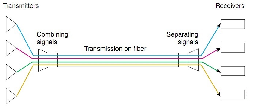
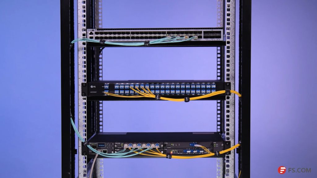
Figure 1: DWDM Networks

DWDM (Dense Wavelength Division Multiplexing) is an associate extension of optical networking. It can put data signals from different sources together on a single optical fiber pair, with each signal simultaneously carried on its own separate light wavelength. With DWDM, up to 160 wavelengths with a spacing of 0.8/0.4 nm (100 GHz/50 GHz grid) separate wavelengths or channels of data can be transmitted over a single optical fiber.

DWDM Networks Components

Conventionally, for DWDM networks, there are four devices showed as below that are commonly used by IT workers:

  • Optical transmitters/receivers
  • DWDM mux/demux filters
  • Optical add/drop multiplexers (OADMs)
  • Optical amplifiers transponders (wavelength converters)

DWDM Networks Over Long Distance Transmission Solutions

Scenario 1: 40 km Transmission
40km DWDM Network

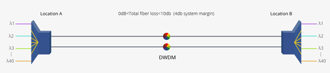
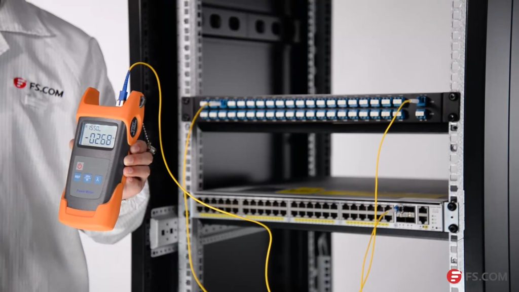
Figure 2: 40km DWDM Network

For this case, the 80km DWDM SFP+ modules and 40ch DWDM Mux/Demuxs are recommended to use. Since the 80km DWDM SFP+ modules are able to support 10G transmission over 40 km, no additional device is needed under this scenario.

Scenario 2: 80 km Transmission
80km DWDM Network

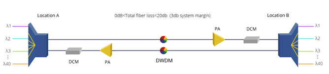
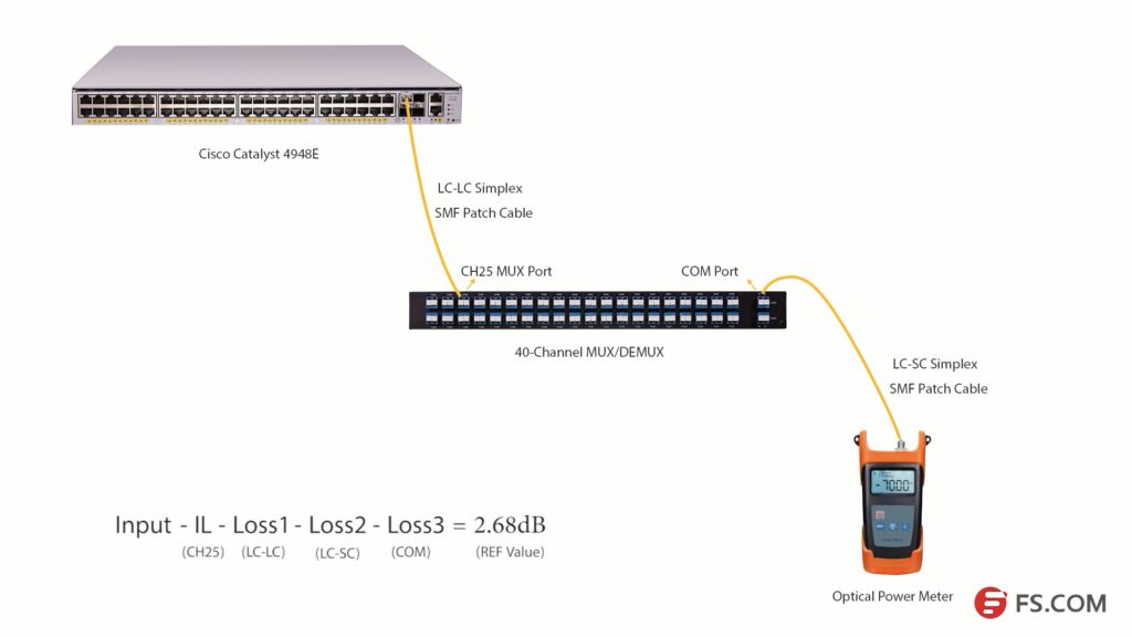
Figure 3: 80km DWDM Network

Deploying this 80 km DWDM network, we will still use 80km DWDM SFP+ modules and 40ch DWDM Mux/Demuxs. The light source of 80km DWDM SFP+ modules might not be able to support such long transmission distance, as there might be a light loss during transmission. In this case, pre-amplifier (PA) is usually deployed before the location A and location B to improve the receiver sensitivity and extend signal transmission DWDM distance. Meanwhile, the dispersion compensation module (DCM) can be added to this link to handle the accumulated chromatic dispersion without dropping and regenerating the wavelengths on the link. The above diagram shows the deploying method of this 80km DWDM network.

Scenario 3: 100 km Transmission
100km DWDM Network

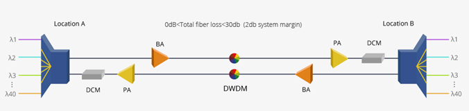
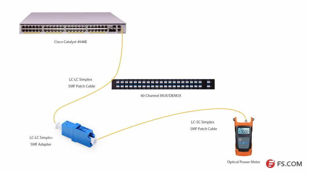
Figure 4: 100km DWDM Network

Under this scenario, the devices used in scenario 2 still need to remain. Since the transmission distance has been increased, the light power will be decreased accordingly. Besides that, you will also need to use booster EDFA (BA) to amplify the optical signal transmission of the 80km DWDM SFP+ modules.

By the way, if you want to extend DWDM transmission distance, you can read this post for solutions: Extend DWDM Network Transmission Distance With Multi-Service Transport Platform.

Factors to Consider in Deploying DWDM Networks

1. Being compatible with existing fiber plant. Some types of older fiber are not suitable for DWDM use. Currently, standard singlemode fiber (G. 652) accounts for the majority of installed fiber, supporting DWDM in the metropolitan area.

2. Having an overall migration and provisioning strategy. Because DWDM is capable of supporting massive growth in bandwidth demands over time without forklift upgrades, it represents a long-term investment. Your deployment should allow for flexible additions of nodes, such as OADMs, to meet the changing demands of customers and usages.

3. Network management tools. A comprehensive network management tool will be needed for provisioning, performance, monitoring, fault identification and isolation, and remedial action. Such a tool should be standards-based (SNMP, for example) and be able to interoperate with the existing operating system. For example, the FMT DWDM solutions from FS.COM are able to support kinds of network management, including NMU line-card, monitor online, simple management tool, and SNMP.

4. Interoperability issues. Because DWDM uses specific wavelengths for transmission, the DWDM wavelengths used must be the same on either end of any given connection. Moreover, other interoperability issues also need to be considered, including power levels, inter- and intra-channel isolation, PMD (polarization mode dispersion) tolerances, and fiber types. All these contribute to the challenges of transmission between different systems at Layer 1.

5. Strategy for protection and restoration. There might have hard failures (equipment failures, such as laser or photodetector, and fiber breaks) and soft failures such as signal degradation (for example, unacceptable BER). Therefore, you need to have a protection strategy while deploying a DWDM network.

6. Optical power budget or link loss budget. Since there might be an optical signal loss over the long distance transmission, it’s critical to have a link loss budget in advance.

Summary

Bringing great scalability and flexibility to fiber networks, the DWDM networks solutions obviously enjoys plenty of strengths, which is also proved to be future-proof. In this post, we make a revelation of the DWDM-based network over long distance transmission. Also, some tips for deploying a DWDM network has also been shared for your reference.

Factors to Consider Before DWDM Network Design

DWDM network deployment usually requires a lot of preparation. There are many factors to be considered before DWDM network design. Even a professional team would take a long time to calculate the parameters over and over to ensure good network performance, let alone some customers who are not experienced. In many cases, customers just have a rough concept of what they need for a DWDM network. When it comes to specific parameters of products, they get no idea. This post offers the most important factors to be considered before DWDM networking. No matter you want to deploy a DWDM network all by your own team, or you want to customize one by other vendors. You will find this post helpful.

DWDM Network Design

What Kind of DWDM Network You Want to Build?

This question contains many details. Here offer several basic factors:

Simplex or Duplex: it is known that DWDM network multiplex different wavelengths together to transmit different ways of optical signals over optical fiber. These wavelengths can be transmitted over the same optical fiber or a pair of optical fibers. Duplex DWDM uses the same for both transmitting and receiving for a way of duplex optical signal over duplex optical fiber. However, the simplex DWDM network uses two different wavelengths for a way of duplex optical signal over a length of single fiber. Thus, the simplex DWDM network provides lower capacity than duplex DWDM network.

Distance: DWDM network gets the greatest returns on investment. It is usually deployed for long distance transmission. But long distance means large light loss. Distance of DWDM network and devices or points it passes should also be considered.

Data Rate and Space Channel: a DWDM network can transmit optical signals of different data rates at the same time. Currently, DWDM network generally transmits 1G and 10G for each wavelength. 1G DWDM SFP, 10G DWDM SFP+ and 10G DWDM XFP modules are usually used. Space Channel of 50 GHz Grid and 100 GHz Grid is commonly applied.

Is There Any Wavelength Adding and Dropping?

The DWDM network needs DWDM MUX/DEMUX for wavelengths multiplexing and de-multiplexing. It is common that a DWDM network passing many places. And wavelengths are required to be added and dropped at some of these places. In this case, DWDM OADM should be used.

DWDM MUX insertion loss test

How to Calculate Light Loss of DWDM Network?

There is light loss in every DWDM network. Technicians should calculate the light loss to decide what devices to be added in the network to ensure good transmission quality. Light loss occurs at many place, the optical fiber for transmission, the DWDM MUX/DEMUX, the devices connected in the network and even the fiber optic splicers and connection points have light loss.

How to Ensure Good DWDM Network Transmission Quality?

There are a variety of factors that can affect the transmission quality. The light source, light loss, transmission distance, fault risks, etc. However, there are always methods to overcome problems. EDFA can be added in the network to ensure enough optical power. If optical power is too strong, fiber optic attenuator can be used. OEO offers conversion between grey wavelengths and DWDM wavelengths. DCM and OLP are separately used for light dispersion compensation and backup line building. These devices can be used properly for good transmission quality.

DWDM MUX

How to Satisfy the Requirements for Both Now and Future?

A DWDM network might only need to transmit several ways of optical signals. However, it might be required to transmission tens of ways optical signals. During the deployment, technician should considerate about the future application. If there is no limit in budget, it would be better to deploy DWDM MUX with more channel port. If not, you can try FS.COM FMU half-U plug-in DWDM MUX modules. You can buy one module for current use and expand the DWDM MUX with another module in the future easily via expansion port on the MUX. All the wavelengths on the DWDM MUX can be customized according to your application.

DWDM long haul

How to Get the Better Performance With Lowest Cost for DWDM Network?

To get the better performance with lowest cost for DWDM network, you need carefully calculate the wavelength, light loss, devices and so on. In practical application, the DWDM network could be really complex, many devices like EDFA, OEO and DCM might be added in the network. It costs a lot for the deployment and management of these devices. Now FS.COM has made these devices into small plug-in cards and offers 1/2/4U chassis to hold them. A free software is also provided for better management and monitoring. This is FS.COM new series of product for DWDM long haul transmission—FMT multi-service transmission platform, which is a cost-effect and high performance system for DWDM network.

Professional Team for DWDM Network Design and Customization

The above mentioned factors are just the basic information that you should consider before DWDM network design. For more professional service and tech support, you can visit FS.COM where you can find professional DWDM network design and customized one-stop solution team and services.

DWDM MUX/DEMUX Insertion Loss Test

During the selection of a DWDM MUX/DEMUX, the insertion loss should always be considered. Generally, a report including the insertion loss value of each port on the DWDM MUX/DEMUX, is usually attached with the product. These values are tested by professional testers. This post will illustrate how to test the insertion loss of DWDM MUX/DEMUX by using an easy-to-get optical power meter.DWDM MUX insertion loss test

Products Required for Insertion Loss Test

We will use Cisco Catalyst 4948E switch and Cisco compatible DWDM SFP+ modules as light source to test the insertion loss of a 40-CH DWDM MUX/DEMUX provided by FS.COM. This DWDM MUX/DEMUX has a typical insertion loss of 3.0 dB. Channel 25 port and Channel 60 port will be tested. The products and tools required are listed as following:

DWDM MUX/DEMUX Insertion Loss Test Steps

First, install the 80km C25 DWDM SFP+ module in the SFP+ port of Cisco Catalyst 4948E. Second, connect the Tx port of the SFP+ module to the Rx port of Channel 25 port with a length of LC-LC simplex single-mode patch cable. Then, connect the TX port of the COM port to the optical power meter with a length of LC-SC simplex single mode patch cable.

Please note to clean all the optical interfaces before connecting to ensure the accuracy of the testing result. The connection is shown in the following picture.

DWDM insertion loss test

Press the λ button to select the wavelength of 1550nm. Then, we will get the optical power value (2.68dB) of the signal from C25 80km DWDM SFP+ module. Light loss occurs when the optical signal pass LC-LC simplex SMF patch cable (Loss1), CH25 port, LC-SC simplex SMF patch cable (Loss2) and COM port (Loss 3) as shown in the above picture.

We get a simple formula here:

Input power – Insertion Loss (CH25) – Loss1-Loss2 -Loss3 = 2.68dB (REF value)

If we want to get the insertion loss value of Channel 25, the formula will be:

Insertion Loss (CH25) = Input power – Loss1 -Loss2 -Loss3 – 2.68dB (REF value)

We can set the 2.68dB as the reference value. And if we can test the optical power value of the channel 25 SFP+ after it experienced these three loss points, the difference value will be the insertion loss of the channel 25 channel port.

DWDM insertion loss test

As the com port could be regarded as an adapter, we will use an adapter to connect the LC-SC and LC-LC patch cables together. Then, connect them to the optical power meter as shown in the above picture, we can get the difference value which is 3.58dB. This value is the insertion loss of the Channel 25 port on this 40Ch DWDM MUX/DEMUX. This value might not be very accurate value, but it is close to it.

DWDM MUX/DEMUX Insertion Loss Testing Video


We have taken a video about how to test the 40CH DWDM MUX/DEMUX insertion loss with optical power meter. You can get more details in this video. All the products and tools in this video are provided by FS.COM. Kindly contact sales@fs.com or visit FS.COM for more if you are interested.