Tag Archives: XFP transceiver

Facts You Should Know About XFP Transceiver

Due to its function of transmitting and receiving signals, transceiver plays an essential role in modern fiber optic networks. There are some common types of transceiver include SFP, SFP+, XFP. XFP transceiver is one of the most useful technological advancements on the market. This text is going to illustrate some facts about XFP.

High-speed computer network and telecommunication links using optical fiber will apply XFP standard for transceivers. XFP transceiver is a 10-Gigabit small form factor pluggable and was defined as the industry standard in 2002, along with other electrical components. The interfaces are often referred to as XFI. XFI electrical interface specification was a 10 gigabit per second chip-to-chip electrical interface specification defined as part of the XFP multi-source agreement.

Hot-Swappable and Protocol-Independent

XFP transceivers are hot-swappable and protocol-independent, which means that you don’t have to shut down the entire device before replacing it. This adorable feature is welcomed by many of the designers who employ XFP transceivers in their designs. Designers who always need to upgrade their devices or have high failure rates in a harsh environment will appreciate the ability to replace devices quickly.

Operation and Application

XFP transceiver generally operates at wavelengths (colors) of 850 nm, 1310 nm or 1550 nm. Principal applications include 10 Gigabit Ethernet, 10 Gbit/s Fibre Channel, synchronous optical networking (SONET) at OC-192 rates, synchronous optical networking STM-64, 10 Gbit/s Optical Transport Network (OTN) OTU-2, and parallel optics links. They can operate over a single wavelength or use dense wavelength-division multiplexing techniques. They include digital diagnostics that provide management that were added to the SFF-8472 standard.

Development

The XFP transceiver specification was developed by the XFP Multi Source Agreement Group. It is an informal agreement of an industry group, not officially endorsed by any standards body. The first preliminary specification was published on March 27, 2002. The first public release was on July 19, 2002. It was adopted on March 3, 2003, and updated with minor updates through August 31, 2005. The chair of the XFP group was Robert Snively of Brocade Communications Systems, and technical editor was Ali Ghiasi of Broadcom. The organization’s website was maintained until 2009.

Types

XFP transceivers are available with numerous types, allowing users to select suitable one to meet their needs.

  • SR – 850 nm, for a maximum of 300 m
  • LR – 1310 nm, for distances up to 10 km
  • ER – 1550 nm, for distances up to 40 km
  • ZR – 1550 nm, for distances up to 80 km

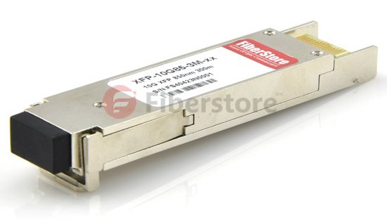
Take 10G XFP for example, there are two types: single mode and multi mode. The following picture is a 10GBASE-SR XFP 850nm 300m Multi-Mode Optical Transceiver.

10G XFP transceiver

Size

The XFP transceiver packaging is smaller than the XENPAK form-factor, which is desirable by many designers. The smaller the footprint, the easier it is to design it into the designs as needed. The best devices support both the XENPAK and the XFP transceiver.

Conclusion

From this text, you can acknowledge above facts about XFP transceiver. The hot-swappable
nature of XFPs and the numerous types contribute to easy configuration and future upgrading. Fiberstore provides a complete range of XFP transceiver modules which can be customized. In addition, it also supplies Compatible XFP transceivers as alternatives to those branded by Cisco, HP, Juniper Networks etc. For more information, please visit Fiberstore.

SFP Telecom Basis

The SFP is the more compact transceiver module used in optical communications. It interfaces a network equipment moter board to a fiber-optic or unshielded twisted pair networking cable.This is probably the most diffused transceiver format available with a variety of different transmitter and receiver types, allowing users to select the appropriate transceiver for each link to provide the required optical reach over the available optical fiber(e.g., multimode fiber or single-mode fiber). In this article, SFP telecom knowledge will be provided.

                   Technology for SFP telecommunications:integrated optics and microelectronics.

          sfp telecom

            FIGURE 1  Pictorial representation and dimensions of a pluggable SFP Transceiver.

A drawing of and SFP Transceiver is presented in Figure 1, where the particular connector for the input and output fibers that, with different dimensions, is present in all the transceivers is evidenced. The way in which the SFP Transceivers are hosted on the motherboard using a suitable cage allowing a hot plug is shown in Figure 1, where both the empty cages on the front of a system card and the cages with plugged SFPs are shown.

SFP module is commonly available in four different categories: 850nm (SX), 1310nm (LX), 1550nm (ZX), and WDM, both DWDM and CWDM. SFP Transceivers are also available with a “copper” cable interface, allowing a host device designed primarily for optical fiber communications to also communicate over unshielded twisted pair net-working cable.
Commercially available transceivers have a capability up to 2.5 Gbit/s for transmission applications; moreover, a version of the standard with a bit rate of 10 Gbit/s exists, but it can be used only to connect nearby equipment, and is very useful to spare space and power consumption as inter face in the client cards of line equipments.Modern optical SFP Transceivers support digital optical monitoring functions accord-ing to the industry standard SFF-8472 MSA. This feature gives the end user the ability to monitor real -time parameters of the SFP, such as optical output power, optical input power, temperature, laser bias current, and transceiver supply voltage. SFP transceivers are designed to support SONET, Gigabit Ethernet, Fiber Channel, and other communications standards.

                                       sfp telecom   

                                    FIGURE 2   Hosting of SFP Transceivers into a system card.

                     sfp telecom

        FIGURE 3   Characteristics of Practical SFP Pluggable Transceivers for Different Applications

The standard is expanding to SFP+, which will be able to support data rates up to 10.0 Gbit/s(that will include the data rates for 8 Gbit Fiber Channel, and 10 GbE). possible per-formances of different realistic SFP Transceivers are reported in FIGURE 3.

XFP Transceivers for Telecommunications

The MSA for the XFP transceiver was born after the start of the success of the SFP format to provide a transceiver with a form factor suitable to host 10Gbit/s transmission compo-nents, but sufficiently compact to reproduce the advantages of the SFP.
In a short time it was evident that the XFP industrial standard was really tailored according to the system needs and at present this is the only type of transceiver used in thelecom equipments whose evolution is targeted to high-performance interfaces at 10 Gbit/s.
At the beginning the target was a simple short-reach or medium-reach interface, but the evolution of the lasers and the Mach-Zehnder modulators integrated on InP platform is driving the development of a new generation of high-performance XFPs with tunable long-reach interfaces.
Thus, at present, there are a large number of different XFP transceivers designed for telecommunications: from the transceivers with gray short-reach interfaces for application in the client ports of optical equipments to short-, intermediate-, and long-reach DWDM interfaces, both with fixed and tunable lasers, to CWDM10 Gbit/s transceivers.

                          Technology for Telecommunications:Integrated Optics and Microelectronics

                          XFP telecom                                  
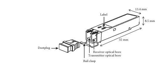
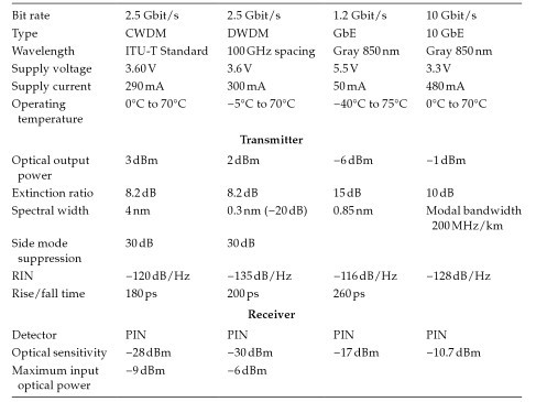
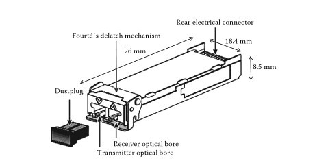
FIGURE 4   Pictorial representation and dimensions of a pluggable XFP transceiver.

The drawing of an XFP transceiver is presented in Figure 4 with the indication of the transceiver main dimensions.XFP transceivers are slightly greater than SFPs, but they are by far the smaller 10 Gbit/s interfaces suitable for DWDM transmission, and even if the transmission performances attainable with MSA 300 PIN are better,seceral optical systems, even when requiring long-haul transmission, adopt XFPs. As a matter of fact, the advantages in terms of space, power consumption, and failure management often over-commpensate a certain transmission penalty.

The way an XFP is hosted on the motherboard is shown in Figure 5. As in the case of the SFP there is asuitable cage that has to be mounted on the motherboard in order to allow the XFP hot plug. Since high-performance XFPs have a high ratio between power consumption and area of contact with the cooling air flux, a heat sink is generally needed to increase the heat exchange area. This is mounted directly on the cage to minimize the thermal resistance.(Related products in: xfp-10gzr-oc192lr)

                      XFP telecom

                                 FIGURE 5   Hosting of XFP transceivers into a system card.

                      XFP telecom                        
                     FIGURE 6   Functional scheme of a DWDM 10 Gbit/s XFP transceiver.

The functional diagram of a high-performance XFP is shown in Figure 6. From the figure it results that the module is controlled via an inter face, the same that is used also to control MSA 300 modules. This clearly declares the fact that an XFP is not conceived as a low-performance module; on the contrary, it is equipped with a sufficiently powerful control interface to allow even the most complex features to be configured and managed. Hope the knowledge of SFP telecom and XFP telecom