Category Archives: Fiber Optic Cable

Making PLBs and tethering antigens to PLBs

We describe tethering the model Ag, NIP, or a surrogate Ag, anti-lg to PLBs. The method can be generalized to attach any biotinylated or Histagged molecule to biotin-or nickel-caontaining PLBs, respectively.
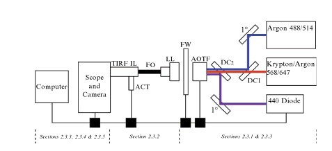
1222222222222

                                                         Figure 1

Figure 1 System design. Shown is a generalized diagram of the TIRFM rigs components are noted beneath the figure. All optical components to the right of the Fiber Optic Cable are mounted on a metal breadboard with screws on standard post mounts. Three lasers(boxes on right) are used to provide five usable excitation lines(wavelengths in nm indicated). After reflection on a primary mirror, the argon laser lines are directed to the AOTF via a dichroic mirror(DC1). The krypton-argon lines pass through both DC1 and DC2. After reflection on a primary mirror, the 440-nm diode laser line is directed to the AOTF via DC2. Power at the 440-nm laser head is computer controlled. Control boxes are required to interface with the computer software and are depicted as black boxes. Thin black lines at the bottom of the figure indicate computer connections. The AOTF and excitation filter wheel(FW) are linked to their respective control boxes, which in turn are coupled to the PC workstation and are controlled by MetaMorph acquisition software. The selected line is directed to the laser launch(LL) lens to allow entry into the fiber optic cable. The fiber optic cable is coupled to the TIRF illuminator (TIRFIL).The TIRF angle is controlled through the software via a motorized actuator(ACT).

Excitation light source

Continuous wave lasers provide the illumination source for our TIR FM systems. Typical laser types include gas, diode-pumped, and straight diode; all can be used in combination. The lasers are mounted on an optical breadboard with their polarity and vertical beam heights matched so that they can be combined into a single-mode fiber optic cable, which carries the light to the TIRFM illuminator on the microscope as schematically illustrated in FIG.2

Mixed gas lasers provide an economic means to obtain m ultiple laser lines from a single device. Wavelength selection is accomplished using a sofware-controlled, acousto-optical tunable filter(AOTF). Because of the inadequate blocking power of the AOTF and the fact that gas lasers produce multiple usable(and unusable wavelengths, extraneous excitation light must be blocked from reaching the extremely sensitive cameras used in TIRFM with “cleanup” excitation filters. On our systems, the cleanup filters are placed in a software-controlled filter wheel(FW) on the breadboard after the AOTF to provide versatility and to avoid reflection artifacts that occur if placed in the traditional location within the dichroic beam splitter housing.) (Related products in: Fiber Optic Splitter Box)

Straight diode and diode-pumped solid-state lasers can be up to 10 times smaller in size and are a noise-and heat-free alternative relative to their gas-driven equivalents. Straight diode lasers have a longer life expectancy relative to gas lasers whose tubes must be replaced(usually at a third of the full cost) everu 2-3 years. Straight diodes can be modelated by software control, bypassing the need for an AOTF and thus can be directly linked to a fiber optic cable either at the laser head or, as in the case of our system, mirrored directly into a fiber optic coupler. It is important to note that the square beam shape of a typical diode laser usually results in an unavoidable and significant loss of power throughput at the point of fiber optic coupling. Diode-pumped lasers use a different technology to produce their monochromatic lines and their output must be modelated through an AOTF.

Benefits and Characteristics of Fiber Optic Cable

Fiber optic cable, or simply fiber, contains one or several glass or plastic fibers at its center, or core. Data is transmitted via pulsing light sent from a laser (in the case of 1- and 10-gigabit technologies) or an LED (light-emitting diode) through the central fibers. Surrounding the fibers is a layer of glass or plastic in the strands. It reflects light back to the core in patterns that vary depending on the transmission mode. This reflection allows the fiber to bend around corners without diminishing the integrity of the light-based signal. Outside the cladding, a plastic buffer protects the cladding and core. Because the buffer is opaque, it also absorbs any light that might escape. To prevent the cable from stretching, and to protect the inner core further, strands of Kevlar surround the plastic buffer. Finally, a plastic sheath covers the strands of Kevlar.

Fiber optic cable

Like twisted pair and coaxial cabling, fiber-optic cabling comes in a number of different varieties, depending on its interned use and the manufacturer. For example, fiber optic cable used to connect the facilities of large telephone and data carries may contain as many as 1000 fibers and be heavily sheathed to prevent damage from extreme environmental conditions. At the other end of the spectrum, fiber optic patch cables for use on LANs may contain only two stands of fiber and be pliable enough to wrap around your hand. Because each strands of glass in a fiber optic cable transmits in one direction only-in simplex fashion-two strands are needed for full-duplex combined side by side in conjoined jackets. You’ll find zipcords where fiber optic cable spans relatively short distances, such as connecting a sever and switch. A zipcord may come with types of connectors on its ends, as described later in this section.

Fiber optic cable provides the following benefits over copper cabling:

  • Extremely high throughput
  • Very high resistance to noise
  • Excellent security
  • Ability to carry signals for much longer distances before requiring repeaters than copper cable
  • Industry standard for high-speed networking

The most significant drawback to the use of fiber is that covering a certain distance with fiber optic cable is more expensive than using twisted pair cable. Also, fiber-optic cable requires special equipment to splice, which means that quickly repairing a fiber-optic cable in the field (given little time or resources) can be difficult. Fiber’s characteristics are summarized in the following list:

  • Throughput – Fiber is reliable in transmitting data at rates that can reach 100 gigabits(or 100,000 megabits) per second per channel. Fiber’s amazing throughput is partly due to the physics of light traveling through glass. Unlike electric pulses traveling over copper, the light experiences virtually no resistance. Therefore, light-based signals can be transmitted at faster rates and with fewer errors than electric pulses. In fact, a pure glass strand can accept up to 1 billion laser light pules per second. Its high throughput capability makes it suitable for network backbones and for serving applications that generate a great deal of traffic, such as video or audio conferencing.
  • Cost – Fiber optic cable is the most expensive transmission medium. Because of its cost, most organizations find it impractical to run fiber to every desktop. Not only is the cable itself more expensive than copper cabling, but fiber optic transmitters and connectivity equipment can cost as much as five times more than those designed for UTP networks. In addition, hiring skilled fiber cable installers costs more than hiring twisted pair cable installers. However, as technologies improved, fiber optic cables are cheaper and cheaper. (Click to find the fiber optic cable price in Fiberstore)
  • Connectors – With fiber cabling, you can use any of 10 different types of connectors. The figures below show four of the most common connector type: the SC (subscriber connector or standard connector), ST (straight tip), LC (local connector) , and MT-RJ (mechanical transfer redistered jack). Existing fiber networks might use ST or SC connectors. However, LC and MT-RJ connectors are used on the very latest fiber optic technology. LC and MT-RJ connectors are preferable to ST and SC connectors because of their smaller size, which allows for a higher density of connections at each termination point. The MT-RJ connector is unique because it contains two strands of fiber in a single ferrule, which is a short tube within a connector that encircles the fiber and keeps it properly aligned. With two strands in each ferrule, a single MT-RJ connector provides for full-duplex signaling. Linking devices that require different connectors is simple because you can purchase fiber optic cables with different connector types at each end.
    Fiberstore
    Fiberstore
    Fiberstore
    Fiberstore
  • Noise immunity – Because fiber does not conduct electrical current to transmit signals, it is unaffected by EMI. Its impressive noise resistance is one reason why fiber can span such long distances before it requires repeaters to regenerate its signal.
  • Size and scalability – Depending on the type of fiber optic cable used, segment lengths vary from 150 to 40,000 meters. This limit is due primarily to optical loss, or the degradation of light signal after it travels a certain distance away from its source (just as the light of a flashlight dims after a certain number of feet). Optical loss accrues over long distances and grows with every connection point in the fiber network. Dust or oil in a connection (for example, from people handling the fiber while splicing it) can further exacerbate optical loss. Some types of fiber-optic cable can carry signals 40 miles while others are suited for distances under a mile. The distance a cable can carry light depends partly on the light’s wavelength. It also depends on whether the cable is single mode or multi-mode.

About Fiberstore:

As one of the world’s largest supplier, Fiberstore provides the most comprehensive fiber optic cables including armored fiber optic cables, LSZH fiber optic cables, figure 8 aerial fiber optic cables, ADSS fiber optic cables, etc.

Related articles: Fiber Optic Connector Types, Market, & Installation

                             How to Select Fiber Optic Cables of High Quality?

Difference between Fiber Pigtail & patch cords

Optical fiber patch cords are made from either single or multi-fiber cables (usually rated for indoor use) and connected at each end with an optical connector (either single fiber or multiple-fiber connector). Sometimes patch cords are called jumpers, especially if they are simplex or dulex. The connectors are selected to mate with the interfacing equipment or cable connectors. The important idea is that the cable has a connector at each end. The fiber can be either tight or loose buffered and the cable can be made of various diameters (1.2 mm to 3.0 mm are common). The patch cord may have one type of connector (ST FC, SC, LC, etc) on one end and a different connector on the other as long as all the fibers are connectorized on each cable end – this is a transition jumper. Patch cords are commonly used to connect ports on fiber distribution frames (FDFs).

12fibers SCUPC SM pigtail

fiber pigtail of Fiberstore

mtpmpo3

Fiberstore optical fiber patch cords with mtp connector


A fiber pigtails is a cable (like a pach cord or jumper) with only one end terminated with an optical connector. Patch cords are often cut into shorter lengths to make two pigtails. Pigtails are found anywhere, but more commonly in optical assemblages or optical components (in a box)

Experience of Cut the fiber jumpers

I also have used fiber optic jumpers in place of pigtails for customer directed repairs. I prefer proper equipment use per application, however I have noticed that with a fusion splicer the only complication is either the fan out assembly or the splice tray fit and the lack of color coding possibilities if using only jumpers .I do like the ability of testing a connector prior to splicing it on, but following the pigtail termination I always OTDR the fiber to ensure quality installation. That is followed at the completion of a installation with a light loss meter.

Yes, cutting a jumper gives you 2 connectors. but 2 fiber pigtails are purposed for the task of providing connectors for a permanent link installation. while the jumper is purposed with the task interconnecting two such connectors.
Standard designs that customers receive are clearer to understand as the specific function of each item is known. If the bill of materials reflects : 144 pigtails for 12 individual 6 strand fiber cables and 72 jumpers to connect to equipment to ports provided. but the list of extra jumpers and nonstandard use of jumper cables in a proposed design might be enough to scare a customer away.if i was a contracting officer and I read: 72 jumpers to be used as pigtails for 12 individual 6 strand fiber cables and 72 jumpers to connect to equipment to ports provided.

A clear understanding of the difference between fiber pigtail and patch cord

Previously, I only know different in appearance of the fiber pigtail and patch cord. Fiber pigtail vs fiber patch cord: what’s the difference?

The fiber optic patch cord = fiber optic connector + fiber optic cable + fiber optic connector

fiber pigtail vs fiber patch cord

but the fiber optic pigtail = fiber optic connector + fiber optic cable. I think like this is easy to separate between them.

12fibers SCUPC SM pigtail

Recently, I have readed a discussion about the difference between fiber pigtail and patch core. There are so many professinal people to discuss it. They give me a clear understanding that:

Patch cords are made from either single or multi-fiber cables (usually rated for indoor use) and connected at each end with fiber cable connectors (either single fiber or multiple-fiber connector). Sometimes patch cords are called jumpers, especially if they are simplex or dulex. The connectors are selected to mate with the interfacing equipment or cable connectors. The important idea is that the cable has a connector at each end. The fiber can be either tight or loose buffered and the cable can be made of various diameters (1.2 mm to 3.0 mm are common). The patch cord may have one type of connector (ST FC, SC, LC, etc) on one end and a different connector on the other as long as all the fibers are connectorized on each cable end – this is a transition jumper. Patch cords are commonly used to connect ports on fiber distribution frames (FDFs). The  new mpo connecter make it  possible to run a singel cable that automatically terminates 12 fibers in one easy plug in.  Compared to common patch cord with ST FC, SC, LC connetor, MPO cable is a truly innovative and amazing group of products that really takes fiber optics into the new millennium.

mtpmpo3

A pigtail is a cable (like a patch cord or jumper) with only one end terminated with an optical connector. Patch cords are often cut into shorter lengths to make two pigtails. Pigtails are found anywhere, but more commonly in optical assemblages or optical components

Pigtails are installed where they will be protected and spliced,lets say on the inside of the ODF and that’s why they are normally not sheathed. They have a coating corlour so that you slice them on the corresponding corlour on the out coming fiber.
On the other hand patch codes are used between the ODF to the WDM MUX or equipment. If you cut a patch code for use as pigtail then in case of future faulting where you are dealing with multiple pairs it will be difficult. But still if you need to cut the patch code check on its characteristics.

In general, the only major physical difference b/w patch cord & pigtail is that patch cord is a fixed length piece of cable with dual ended fiber connector type may vary & pigtail is one meter standard OFC core with white white colored jacket. As per standard pigtail can only be used for OFC termination purpose & patch cord is to be used to connect the active component with ODF so that means pigtail can not be used at the place of patch cord.

Related Article: Fiber Optic Pigtail: What Is It and How to Splice It?