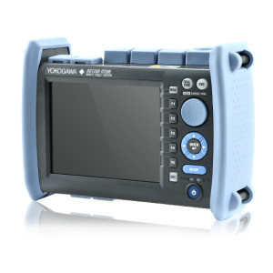
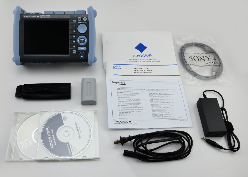
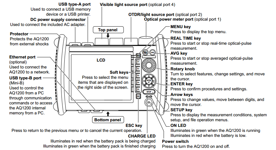
OTDR is a popular fiber optic testing tool which can be used to test the fiber loss, and locate the faults in fiber optic links. However, the OTDR dead zone will affect the testing result and the application of OTDR. To overcome OTDR dead zone during fiber optic testing, launch fiber is being added between OTDR and optical fiber link under test. OTDR launch fiber comes in different types of packages. OTDR launch box and OTDR launch fiber ring are the most commonly used launch fibers.
OTDR insert pulses of light into fiber optic link and measure the back reflection caused by fiber faults to locate the faults. If a long fiber link is required to be tested, a lot of optical power should be inserted into the optical fiber to make sure that the light can be seen at the other end. If powerful optical pulses are inserted into optical fiber, pulse width of the launched optical signal will be increased, which will cause the dead zone at a length of fiber and affect the testing result of OTDR. This dead zone might be hundreds or thousands meters long.
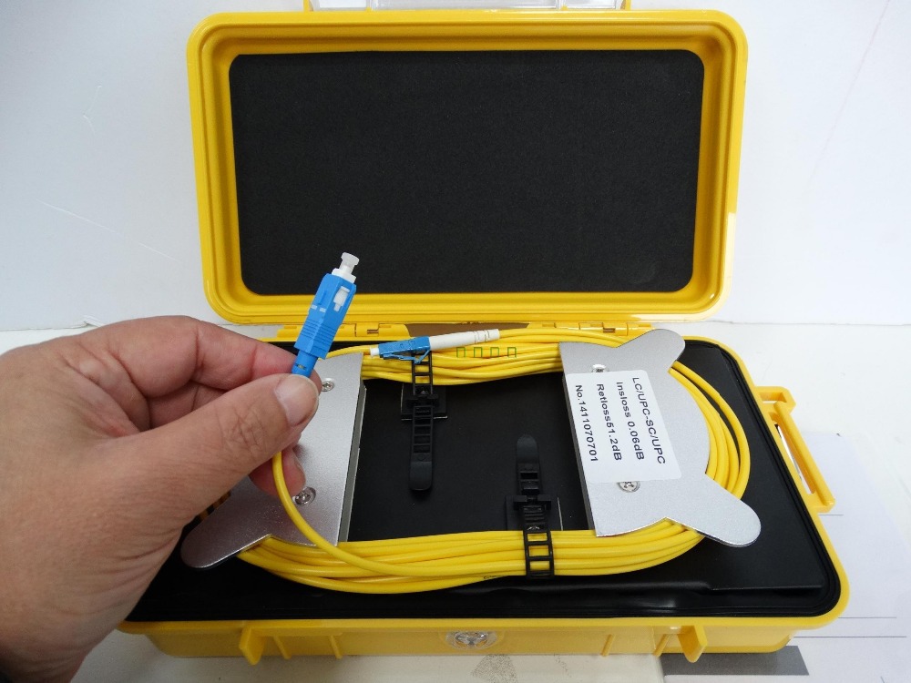
To minimize the affection of the OTDR dead zone during fiber optic testing. A length of long enough optical fiber is being added between the OTDR and the fiber under test. In this way, the OTDR dead zone will happen in this additional optical fiber. The launch fiber is actually a length of optical fiber which is long enough to cover the OTDR dead zone to increase the testing accuracy. Launch fiber is usually terminated with a connector on each end to connect the OTDR with the fiber link under test.
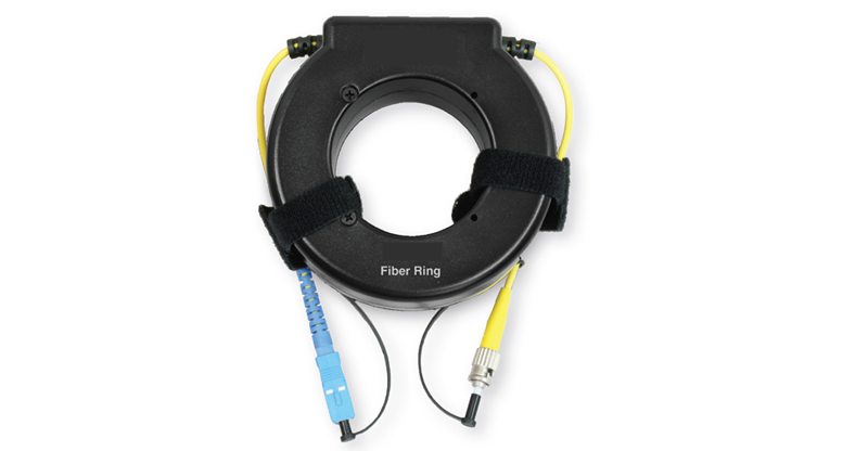
OTDR launch fiber mainly has two designs, one is fiber ring design and the other is box design, separately known as launch fiber ring and OTDR launch box or OTDR dead zone box. The using of them is generally the same. Here offer two situations about how to use OTDR launch fiber.
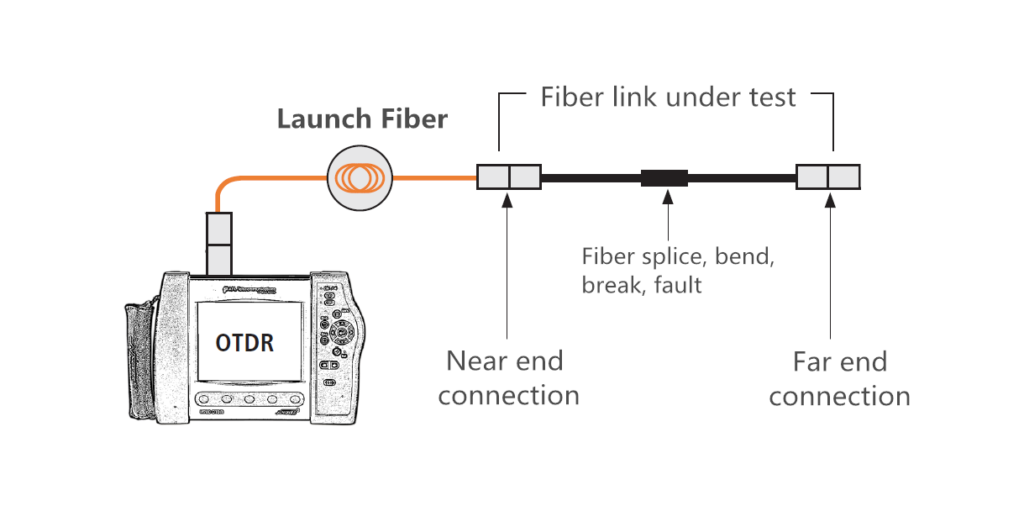
In some cables, launch cable is being used to cover the dead zone at the beginning of the fiber link. In these cases, OTDR launch fiber or OTDR launch box is deployed between the OTDR and the near end connection as shown in the above picture. This allows the accurate measurement of the fiber loss at the near end connection.
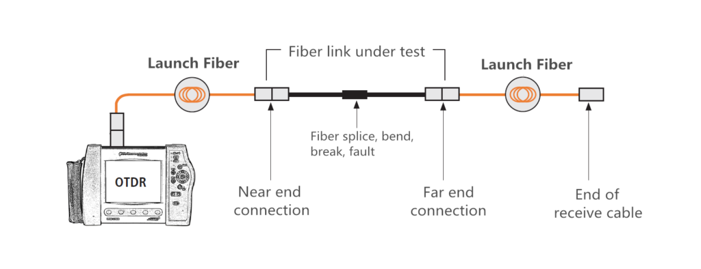
In some cases, the fiber loss at the far end connection should also be tested. Then, the launch fiber can be installed added at the far end connection to work as a receive cable, as shown in the above picture.
Please note that the launch fiber you used for testing should have the same fiber types (OS2, OM1, OM2, OM3, OM4) as the optical fiber under test.
Using launch fiber to overcome OTDR dead zone is the choice in most cases, especially for long optical fiber testing. Let the OTDR dead zone occur in the launch cable to ensure the accurate testing result. Launch fiber is suggested to be added at the beginning and the end of the fiber optic link, if the light loss of the whole fiber link is required. If you want to need more specific details about OTDR launch box, kindly visit another article: Why Do You Need OTDR Launch Box

