Author Archives: Alice Gui

LC-LC Patch Cable in Data Center

LC-LC patch cable has already become the main force of high density cabling network infrastructure. To future increase the profits of LC-LC fiber patch cable, manufactures has invented LC-LC patch cables of different features to meet various requirements in data center and increase the network performance.

What Kind of Fiber Patch Cable Is Required in Data Center?

Data center is a place of thousands fiber links. The selection of fiber patch cables will directly affect the network performance. More and more data centers choose to select fiber patch cable of high performance. Generally, insertion loss and return loss of connectors terminated on patch cable and light loss of optical fiber used for fiber patch cable are three most basic factors for fiber patch cable selection. To satisfy the increasing demands for higher density and easier management in data center, the optimization of fiber patch cable has never stopped. The following introduces several popular LC-LC fiber patch cables which represent the trends of fiber patch cable that data center is asking for.
LC-LC fiber patch cable

Low Insertion Loss and Bend Loss LC-LC Patch Cable

When a length of fiber patch cable is connected in network, optical light loss occurs at the optical fiber and the connectors terminated on it. There are different optical light losses, among which insertion loss at the connectors and bend loss in fiber optic cables are the two most commonly light losses that technicians are trying to overcome. Manufactures provides LC-LC fiber patch cables which can minimize these losses to the most.

Insertion loss refers to the fiber optic light loss caused when a fiber optic component insert into another one to form the fiber optic link. To provide low insertion loss patch cable, LC connectors terminated on the patch cable has been optimized. Standard LC-LC patch cable usually has an insertion loss less than 0.3 dB. However, for upgraded LC-LC patch cable, the insertion loss is usually lower than 0.2 dB. To decrease the bend loss, a type of bend insensitive fiber (BIF) has been used in fiber patch cable. With optimized LC connectors and bend insensitive fiber, LC-LC fiber patch cable could provide lower light loss during network transmission.
uniboot LC cable

High Density LC-LC Patch Cable

LC connector was invented for higher cabling density. standard duplex LC-LC fiber patch cable can provide much higher cabling density than other duplex fiber patch cables. To further increase cabling density in data center, the connectors and cable diameter of LC-LC patch cable are becoming smaller. Uniboot LC-LC patch cable is a typical example. This kind of fiber patch cable designed the two fibers of the duplex patch cable into a single cable. In adding the two connectors terminated at each end of the duplex patch cable share the same boot. With less using cable counts, uniboot patch cable can provide higher cabling density and better cooling environment in data center.

Polarity Switchable LC-LC Patch Cable

The development of patch cable won’t stop at low loss and high density. Making fiber patch cable easier-to-use is also important. Polarity of fiber patch cable matters a lot during installation of fiber patch cable, especially for duplex fiber patch cable and MTP patch cable. It is common to change the polarity of a duplex patch cable during deployment. Technicians might need tools to change the polarity of patch cable. However, a polarity switchable LC-LC patch cable can make things much easier. Without any tools you can polarity reversal could be really easy. The following picture shows the polarity reversal of a special designed LC-LC patch cable.

polarity switchable LC patch cable

Conclusion

LC-LC patch cable has been designed into many different types. A high performance fiber patch cable should not only provide low insertion loss and bend loss, but also higher cabling density and easy-to-use features. This is also the trend of data center development.

Factors to Consider Before DWDM Network Design

DWDM network deployment usually requires a lot of preparation. There are many factors to be considered before DWDM network design. Even a professional team would take a long time to calculate the parameters over and over to ensure good network performance, let alone some customers who are not experienced. In many cases, customers just have a rough concept of what they need for a DWDM network. When it comes to specific parameters of products, they get no idea. This post offers the most important factors to be considered before DWDM networking. No matter you want to deploy a DWDM network all by your own team, or you want to customize one by other vendors. You will find this post helpful.

DWDM Network Design

What Kind of DWDM Network You Want to Build?

This question contains many details. Here offer several basic factors:

Simplex or Duplex: it is known that DWDM network multiplex different wavelengths together to transmit different ways of optical signals over optical fiber. These wavelengths can be transmitted over the same optical fiber or a pair of optical fibers. Duplex DWDM uses the same for both transmitting and receiving for a way of duplex optical signal over duplex optical fiber. However, the simplex DWDM network uses two different wavelengths for a way of duplex optical signal over a length of single fiber. Thus, the simplex DWDM network provides lower capacity than duplex DWDM network.

Distance: DWDM network gets the greatest returns on investment. It is usually deployed for long distance transmission. But long distance means large light loss. Distance of DWDM network and devices or points it passes should also be considered.

Data Rate and Space Channel: a DWDM network can transmit optical signals of different data rates at the same time. Currently, DWDM network generally transmits 1G and 10G for each wavelength. 1G DWDM SFP, 10G DWDM SFP+ and 10G DWDM XFP modules are usually used. Space Channel of 50 GHz Grid and 100 GHz Grid is commonly applied.

Is There Any Wavelength Adding and Dropping?

The DWDM network needs DWDM MUX/DEMUX for wavelengths multiplexing and de-multiplexing. It is common that a DWDM network passing many places. And wavelengths are required to be added and dropped at some of these places. In this case, DWDM OADM should be used.

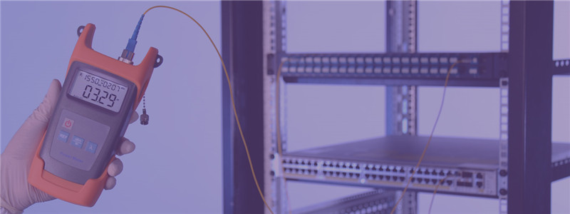
DWDM MUX insertion loss test

How to Calculate Light Loss of DWDM Network?

There is light loss in every DWDM network. Technicians should calculate the light loss to decide what devices to be added in the network to ensure good transmission quality. Light loss occurs at many place, the optical fiber for transmission, the DWDM MUX/DEMUX, the devices connected in the network and even the fiber optic splicers and connection points have light loss.

How to Ensure Good DWDM Network Transmission Quality?

There are a variety of factors that can affect the transmission quality. The light source, light loss, transmission distance, fault risks, etc. However, there are always methods to overcome problems. EDFA can be added in the network to ensure enough optical power. If optical power is too strong, fiber optic attenuator can be used. OEO offers conversion between grey wavelengths and DWDM wavelengths. DCM and OLP are separately used for light dispersion compensation and backup line building. These devices can be used properly for good transmission quality.

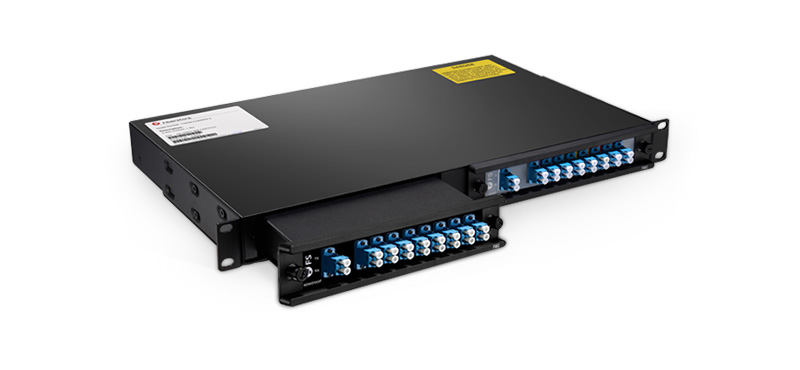
DWDM MUX

How to Satisfy the Requirements for Both Now and Future?

A DWDM network might only need to transmit several ways of optical signals. However, it might be required to transmission tens of ways optical signals. During the deployment, technician should considerate about the future application. If there is no limit in budget, it would be better to deploy DWDM MUX with more channel port. If not, you can try FS.COM FMU half-U plug-in DWDM MUX modules. You can buy one module for current use and expand the DWDM MUX with another module in the future easily via expansion port on the MUX. All the wavelengths on the DWDM MUX can be customized according to your application.

DWDM long haul

How to Get the Better Performance With Lowest Cost for DWDM Network?

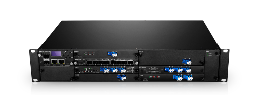
To get the better performance with lowest cost for DWDM network, you need carefully calculate the wavelength, light loss, devices and so on. In practical application, the DWDM network could be really complex, many devices like EDFA, OEO and DCM might be added in the network. It costs a lot for the deployment and management of these devices. Now FS.COM has made these devices into small plug-in cards and offers 1/2/4U chassis to hold them. A free software is also provided for better management and monitoring. This is FS.COM new series of product for DWDM long haul transmission—FMT multi-service transmission platform, which is a cost-effect and high performance system for DWDM network.

Professional Team for DWDM Network Design and Customization

The above mentioned factors are just the basic information that you should consider before DWDM network design. For more professional service and tech support, you can visit FS.COM where you can find professional DWDM network design and customized one-stop solution team and services.

DWDM MUX/DEMUX Insertion Loss Test

During the selection of a DWDM MUX/DEMUX, the insertion loss should always be considered. Generally, a report including the insertion loss value of each port on the DWDM MUX/DEMUX, is usually attached with the product. These values are tested by professional testers. This post will illustrate how to test the insertion loss of DWDM MUX/DEMUX by using an easy-to-get optical power meter.DWDM MUX insertion loss test

Products Required for Insertion Loss Test

We will use Cisco Catalyst 4948E switch and Cisco compatible DWDM SFP+ modules as light source to test the insertion loss of a 40-CH DWDM MUX/DEMUX provided by FS.COM. This DWDM MUX/DEMUX has a typical insertion loss of 3.0 dB. Channel 25 port and Channel 60 port will be tested. The products and tools required are listed as following:

DWDM MUX/DEMUX Insertion Loss Test Steps

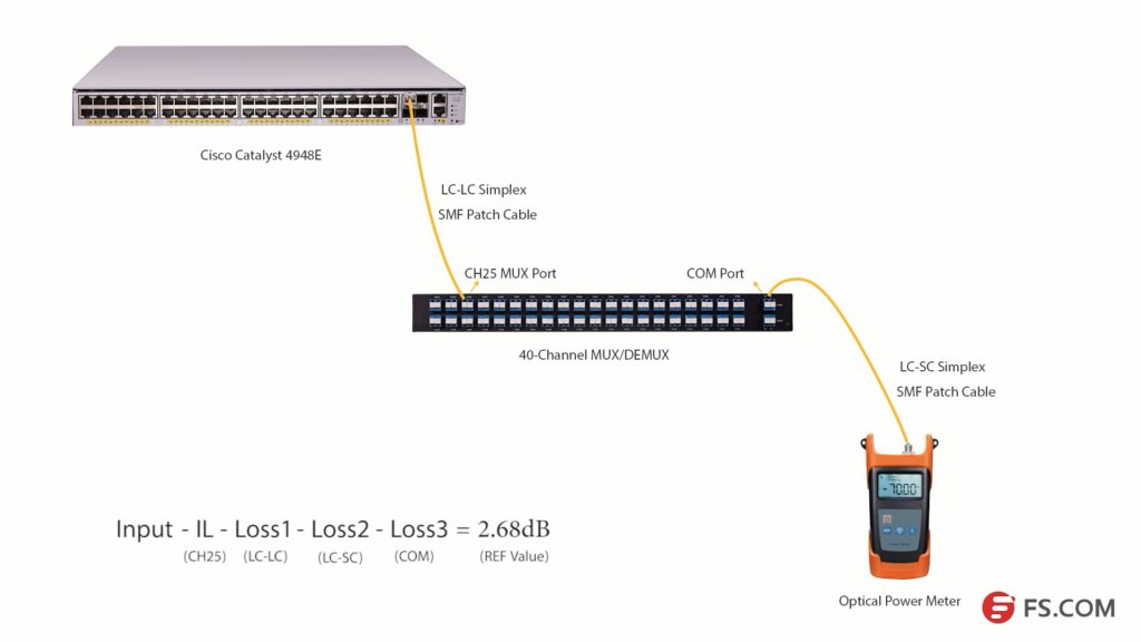
First, install the 80km C25 DWDM SFP+ module in the SFP+ port of Cisco Catalyst 4948E. Second, connect the Tx port of the SFP+ module to the Rx port of Channel 25 port with a length of LC-LC simplex single-mode patch cable. Then, connect the TX port of the COM port to the optical power meter with a length of LC-SC simplex single mode patch cable.

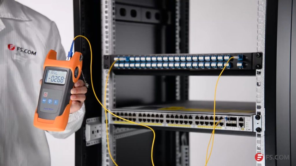
Please note to clean all the optical interfaces before connecting to ensure the accuracy of the testing result. The connection is shown in the following picture.

DWDM insertion loss test

Press the λ button to select the wavelength of 1550nm. Then, we will get the optical power value (2.68dB) of the signal from C25 80km DWDM SFP+ module. Light loss occurs when the optical signal pass LC-LC simplex SMF patch cable (Loss1), CH25 port, LC-SC simplex SMF patch cable (Loss2) and COM port (Loss 3) as shown in the above picture.

We get a simple formula here:

Input power – Insertion Loss (CH25) – Loss1-Loss2 -Loss3 = 2.68dB (REF value)

If we want to get the insertion loss value of Channel 25, the formula will be:

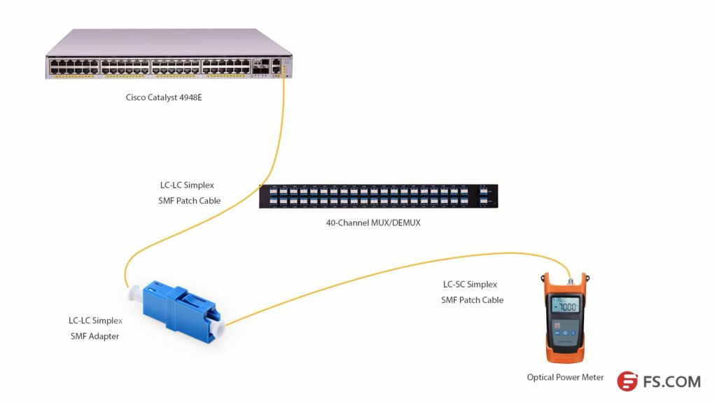
Insertion Loss (CH25) = Input power – Loss1 -Loss2 -Loss3 – 2.68dB (REF value)

We can set the 2.68dB as the reference value. And if we can test the optical power value of the channel 25 SFP+ after it experienced these three loss points, the difference value will be the insertion loss of the channel 25 channel port.

DWDM insertion loss test

As the com port could be regarded as an adapter, we will use an adapter to connect the LC-SC and LC-LC patch cables together. Then, connect them to the optical power meter as shown in the above picture, we can get the difference value which is 3.58dB. This value is the insertion loss of the Channel 25 port on this 40Ch DWDM MUX/DEMUX. This value might not be very accurate value, but it is close to it.

DWDM MUX/DEMUX Insertion Loss Testing Video


We have taken a video about how to test the 40CH DWDM MUX/DEMUX insertion loss with optical power meter. You can get more details in this video. All the products and tools in this video are provided by FS.COM. Kindly contact sales@fs.com or visit FS.COM for more if you are interested.

8-Fiber MTP VS. 12-Fiber MTP Cables

MTP fiber cable in data center becomes increasingly popular in data center with the wide deployment of 40G and 100G network. It is common that 40G and 100G network usually based on 12-fiber MTP networking system. However, not all the 12 fibers of MTP cable are used.8-fiber MTP cable

12-Fiber MTP Cable During Transmission

There are usually 4 fibers left unused, if you are using a 12-fiber MTP cable to transmit 40G with QSFP+ module or 100G with QSFP28 module. The following shows how 12-fiber MTP fiber cable works when it is used to be connected with 40Gbase-SR4 QSFP+ module. If more 12-fiber MTP cables are used, more optical fibers will be wasted. As IEEE standards like 40GBASE-SR4 and 40GBASE-SR10 uses only 8 fibers for dual-way transmission, manufacturers provide new versions of MTP fiber cable which contains only 8 optical fibers but still used the standard MTP interfaces.40gbase-sr4

Base-8 MTP for Higher Density and Lower Utilization

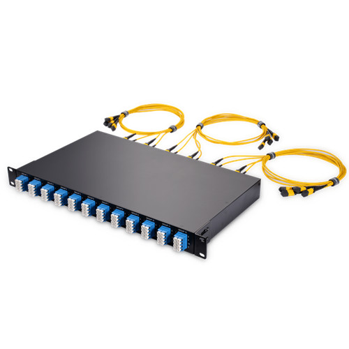
Network built with 8-fiber MTP system can transmit the same data with less cost and higher density compared with 12-fiber MTP system. All fiber will be 100% utilized in base-8 MTP products. It could be a cost-effect solution for both 40G to 40G transmission and 40G to 10G transmission. 8-fiber MTP trunk cables and 8-fiber MTP-LC harness cable are already provided in the market. There are also rack designed 8-Fiber MTP breakout panels for 40G to 10G applications.

MTP-LC-harness-cable MTP-LC-harness-cable
MTP-LC Harness Cable MTP-LC 40/100G Breakout Panel

Convert 12-Fiber MTP to 8-Fiber MTP Cabling System

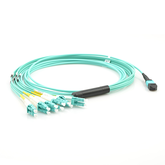
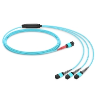
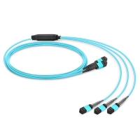
However, most MTP cabling systems are based on 12-fiber or 24-fiber MTP system, especially for backbone cabling. MTP conversion cables are provided in the market which offer conversion between 12/24-fiber MTP and 8-fiber MTP cabling systems. The following shows two types of 8-fiber MTP conversion cables which can provide 12-fiber to 8-fiber MTP conversion and 24-fiber to 8-fiber MTP conversion separately.

24 to 8 fiber MTP conversion cable 12 to 8 fiber MTP conversion cable
1*3 MTP Conversion Cable 2*3 MTP Conversion Cable

If you have already deployed 12-fiber MTP cabling system in your data center, 2*3 MTP conversion cable is suggested to be used. With one end terminated with two 12-fiber MTP cable and the other end terminated with three 8-fiber MTP connectors, 12-fiber to 8-fiber MTP cabling conversion could be achieved, as well as 100% optical fiber utilization in 12-fiber MTP system.

1*3 MTP conversion cable has a 24-fiber MTP cable on one end and three 8-fiber MTP cable on the other end. With this cable, a length of 24-fiber MTP cable can provide three ways of 40G signal dual-way transmission. All the fibers in a 24-fiber cabling system cable be used.

Conclusion

It is clear that the 8-fiber, 12-fiber based and 2-fiber based cabling system will exist for a long term in 40/100G network. 8-fiber MTP cabling system can provide higher optical fiber utilization with lower cost and higher cabling density. If you want to transfer 12-fiber MTP system to 8-fiber MTP system, you can use MTP conversion cables. 8-base MTP system, could be regarded as an additional option for the existing fiber network infrastructure.

The Art of DWDM Wavelength-Case Study of DWDM Networking

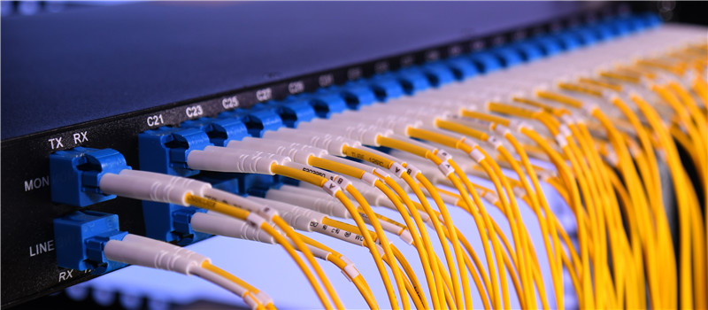
DWDM network is widely accepted as the best solution to increase network capacity over long distances. Making full use of these DWDM wavelengths for transmission needs to consider both now and future. This makes the design of the DWDM network complex. Here shares a true case of DWDM networking, which fulfills the requirement for now, but is also built for the future.DWDM networking

DWDM Networking Requirement

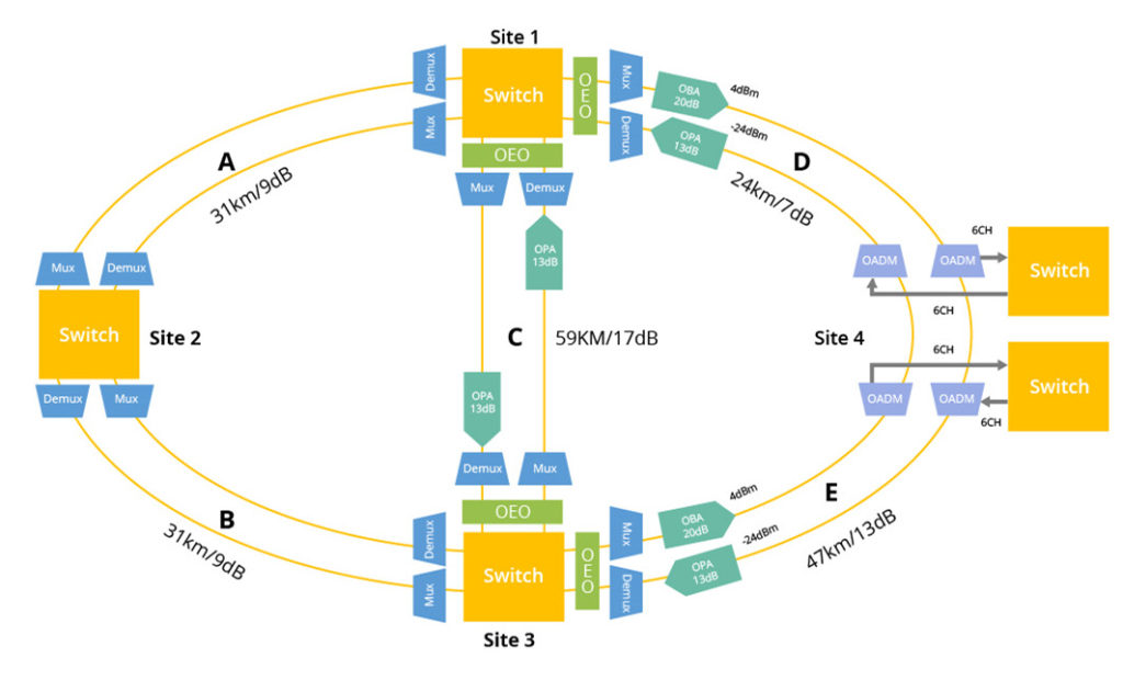
Three duplex DWDM links (Link A, Link B and Link C) should be built between three different sites: Site 1, Site 2 and Site 3. The following table listed the distance and light loss of these three links.

Duplex DWDM Links Distance Light Loss
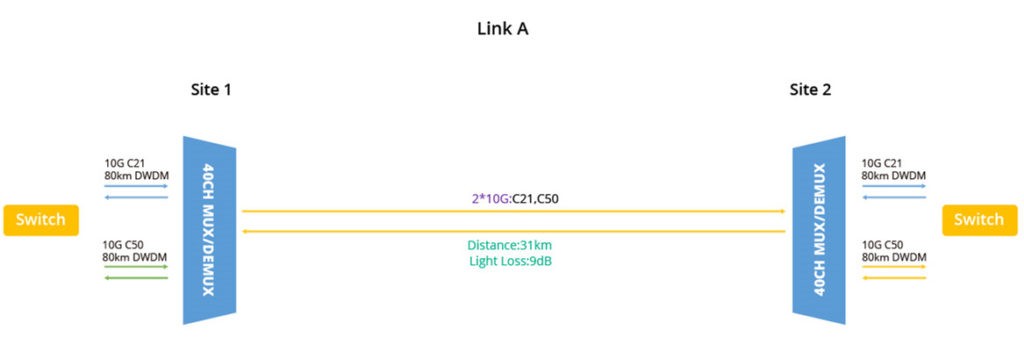
Link A: Site 1 – Site 2 31km 9dB
Link B: Site 2 – Site 3 31km 9dB
Link C: Site 1 – Site 3 59km 17dB

A backup link of Link C should be built as well. This backup link will use as length of dark fiber which passes Site 4. Thus, another two links—Link D and Link E work together as the backup for Link C. Meanwhile, Link D and Link E also work independently for 6 ways of optical transmission. The following table lists the distance and the light loss of these links.

Duplex DWDM Links Distance Light Loss
Link D 24km 7dB
Link E 47km 13dB
Backup Link C (Link D+E) 71km (24km+47km) 20dB (7dB+13dB)
DWDM Networking Solution

As not all the links in this DWDM network are transmitting the same information, different wavelengths should be used. For instance, Link A and Link B only transmit 2 ways of optical signal, while Link C is required to transmit 10 ways of optical signal. And some of them are of different data rates. Assignment of the DWDM wavelengths in these links is very important. Considering the future network expanding needs, Site 1, Site 2 and Site 3 are suggested to deploy 40-Channel DWDM MUX/DEMUXs. The following will offer a detailed solution for each link.2 Channel DWDM network

Link A: 2*10G Over 31km

Link A is from Site 1 to Site 2, which is 31 kilometers long with light loss of 9dB. It only needs to transmit two ways 10G optical signal. In this link, we use DWDM wavelength, C21 and C50 for transmission. DWDM SFP+ modules that support 80km is used. In this link, no other devices are required to booster the optical signals, as the light source from the 80km modules are powerful enough to support this link. The required products on Site 1 and Site 2 are listed in the following table:

Location Product Parameter
Site 1 DWDM MUX/DEMUX 40-Channel
10G 80km DWDM SFP+ C21,C50
Site 2 DWDM MUX/DEMUX 40-Channel
10G 80km DWDM SFP+ C21,C50

2 Channel DWDM network

Link B: 2*10G Over 31km

Link B is from Site 2 to Site 3. Just like Link A, it required to support two ways of 10G transmission over distance of 31km. For Link B, we use the same products as for Link A.

Location Product Parameter
Site 2 DWDM MUX/DEMUX 40-Channel
10G 80km DWDM SFP+ C21,C50
Site 3 DWDM MUX/DEMUX 40-Channel
10G 80km DWDM SFP+ C21,C50
Link C: 2*1G & 8*10G Over 57km

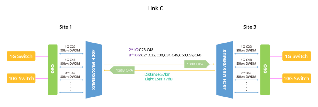
Link C is from Site 1 to Site 3. It is required to transmit 2 ways of 1G optical signal and 8 ways of 10G optical signal at the same time over a distance of 57km with light loss of 17dB. Compared with Link A and Link B, things are much different for Link C, as the distance, network capacity and power consumption are all increased. It means more devices should be added.dwdm link toplogy link c

Overcome Large Light Loss: To ensure that the optical signals are powerful enough to reach the distance, EDFA are suggested to be deployed. An 13dB output booster EDFA is suggested to be deployed after the DWDM MUX Tx end in both Site 1 and Site 3.

Overcome High Power Consumption: As the more wavelengths are used in Link C, more DWDM fiber optic modules should be used. As the power consumption of DWDM modules are higher than normal optical modules, install large sum of DWDM modules in one switch would increase the risk of fault caused by high power consumption. OEO converter which can support the optical wavelengths transmission between normal SMF & MMF wavelengths to DWDM wavelengths are suggested to be deployed between DWDM MUX/DEMUX and switch. This can reduce the fault risk caused by high power consumption effectively.

The product required for Link C are listed as following:

Location Product Parameter
Site 1 DWDM MUX/DEMUX 40-Channel
2*1G 80km DWDM SFP C23, C48
8*10G 80km DWDM SFP+ C21, C22, C30, C31, C49, C50, C59, C60
2*OEO 8-port
EDFA (OPA) 13dB
Site 3 DWDM MUX/DEMUX 40-Channel
2*1G 80km DWDM SFP C23, C48
8*10G 80km DWDM SFP+ C21, C22, C30, C31, C49, C50, C59, C60
2*OEO 8-port
EDFA (OPA) 13dB
Backup Link C = Link D + Link E

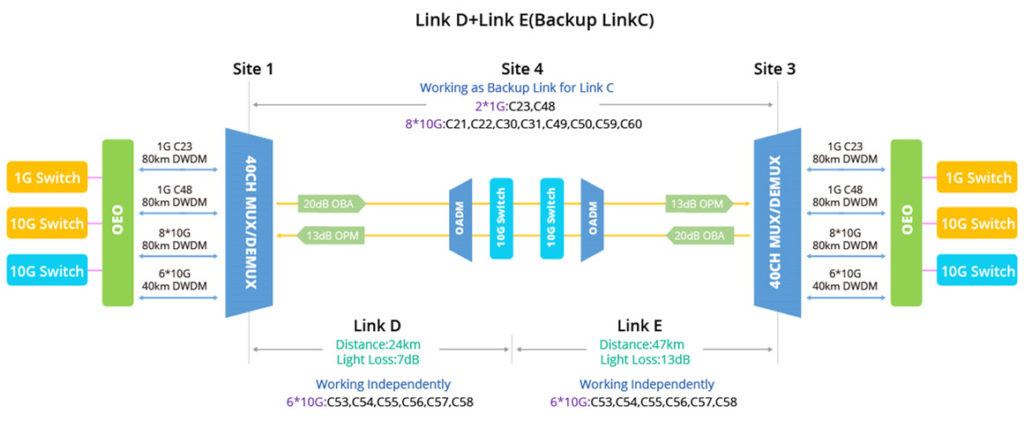
Link D and link E are working together as the backup Link C, so ten different wavelengths should be used as in Link C. Meanwhile, both Link D and Link E are working independently. Both of them are transmitting 6 ways of optical signal. Here we used two OAMDs at Site 4 to multiplex another 6 wavelengths into the existing network. Link D + Link E is 71 kilometers long, which is much longer than Link C. To support this backup link, except the devices used in Link C, 20dB optical booster EDFA is suggested to be added in both Site 1 and Site 3 at the DWDM Mux/DEMUX RX port.backup DWDM link

As Link D is only 24km and link E is 47km, for their independent working, DWDM SFP+ modules support 40km is suggested. The following listed the products for Link D + Link E in Site 1, Site3 and Site 4.

Location Product Parameter Function
Site 1 DWDM MUX/DEMUX 40-Channel Backup of Link C
2*1G 80km DWDM SFP C23, C48
8*10G 80km DWDM SFP+ C21, C22, C30, C31, C49, C50, C59, C60
2*OEO 8-port
EDFA (OPA) 13dB
EDFA (OBA) 20dB
6*10G 40km DWDM SFP+ C53, C54, C55, C56, C57, C58 Link D Works independently
Site 4 6*10G 40km DWDM SFP+ C53, C54, C55, C56, C57, C58
OADM 6-Channel: C53, C54, C55, C56, C57, C58
OADM 6-Channel: C53, C54, C55, C56, C57, C58 Link E Works independently
6*10G 80km DWDM SFP+ C53, C54, C55, C56, C57, C58
Site 3 6*10G 80km DWDM SFP+ C53, C54, C55, C56, C57, C58
DWDM MUX/DEMUX 40-Channel Backup of Link C
2*1G 80km DWDM SFP C23, C48
8*10G 80km DWDM SFP+ C21, C22, C30, C31, C49, C50, C59, C60
2*OEO 8-port
EDFA (OPA) 13dB
EDFA (OBA) 20dB
Products in this DWDM Networking Case

The products mentioned in the above case are all provided by FS.COM. Here offer the details for your reference. In FS.COM, you can offer your requirement for networking to the tech support team and get suitable and reliable performance solutions for your projects.

DWDM MUX/DEMUX 40-CH DWDM MUX/DEMUX
DWDM OADM 6-CH DWDM OADM
DWDM SFP 80km DWDM SFP
DWDM SFP+ 80km DWDM SFP+
40km DWDM SFP+
EDFA 13dB EDFA (OPA)
20dB EDFA (OBA)
Transponder (OEO) 8-Port 3R OEO Converter