Tag Archives: Fiber Optic Cables

LC-LC Patch Cable in Data Center

LC-LC patch cable has already become the main force of high density cabling network infrastructure. To future increase the profits of LC-LC fiber patch cable, manufactures has invented LC-LC patch cables of different features to meet various requirements in data center and increase the network performance.

What Kind of Fiber Patch Cable Is Required in Data Center?

Data center is a place of thousands fiber links. The selection of fiber patch cables will directly affect the network performance. More and more data centers choose to select fiber patch cable of high performance. Generally, insertion loss and return loss of connectors terminated on patch cable and light loss of optical fiber used for fiber patch cable are three most basic factors for fiber patch cable selection. To satisfy the increasing demands for higher density and easier management in data center, the optimization of fiber patch cable has never stopped. The following introduces several popular LC-LC fiber patch cables which represent the trends of fiber patch cable that data center is asking for.
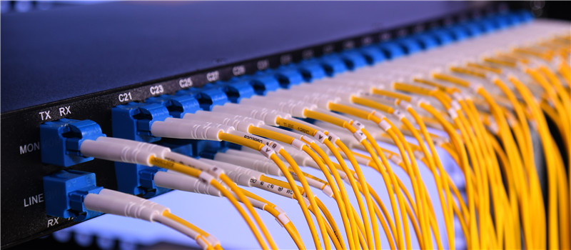
LC-LC fiber patch cable

Low Insertion Loss and Bend Loss LC-LC Patch Cable

When a length of fiber patch cable is connected in network, optical light loss occurs at the optical fiber and the connectors terminated on it. There are different optical light losses, among which insertion loss at the connectors and bend loss in fiber optic cables are the two most commonly light losses that technicians are trying to overcome. Manufactures provides LC-LC fiber patch cables which can minimize these losses to the most.

Insertion loss refers to the fiber optic light loss caused when a fiber optic component insert into another one to form the fiber optic link. To provide low insertion loss patch cable, LC connectors terminated on the patch cable has been optimized. Standard LC-LC patch cable usually has an insertion loss less than 0.3 dB. However, for upgraded LC-LC patch cable, the insertion loss is usually lower than 0.2 dB. To decrease the bend loss, a type of bend insensitive fiber (BIF) has been used in fiber patch cable. With optimized LC connectors and bend insensitive fiber, LC-LC fiber patch cable could provide lower light loss during network transmission.

uniboot LC cable

High Density LC-LC Patch Cable

LC connector was invented for higher cabling density. standard duplex LC-LC fiber patch cable can provide much higher cabling density than other duplex fiber patch cables. To further increase cabling density in data center, the connectors and cable diameter of LC-LC patch cable are becoming smaller. Uniboot LC-LC patch cable is a typical example. This kind of fiber patch cable designed the two fibers of the duplex patch cable into a single cable. In adding the two connectors terminated at each end of the duplex patch cable share the same boot. With less using cable counts, uniboot patch cable can provide higher cabling density and better cooling environment in data center.

Polarity Switchable LC-LC Patch Cable

The development of patch cable won’t stop at low loss and high density. Making fiber patch cable easier-to-use is also important. Polarity of fiber patch cable matters a lot during installation of fiber patch cable, especially for duplex fiber patch cable and MTP patch cable. It is common to change the polarity of a duplex patch cable during deployment. Technicians might need tools to change the polarity of patch cable. However, a polarity switchable LC-LC patch cable can make things much easier. Without any tools you can polarity reversal could be really easy. The following picture shows the polarity reversal of a special designed LC-LC patch cable.

polarity switchable LC patch cable

Conclusion

LC-LC patch cable has been designed into many different types. A high performance fiber patch cable should not only provide low insertion loss and bend loss, but also higher cabling density and easy-to-use features. This is also the trend of data center development.

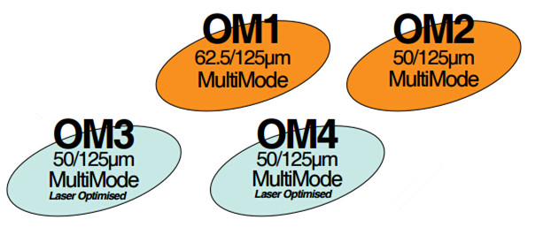
OM1, OM2, OM3, OM4: Standardization of Multi-mode Fiber Optic Cables

Standardization in fiber optic industry is one of the most confusing areas for people who involved in the business. “OM” terminology in fiber optic technology is new to both users and fiber optic manufacturers. The letters “OM” stand for optical multi-mode, which is marked multi-mode optical fiber specifications. There are four standards in fiber optic terminology: OM1, OM2, OM3, OM4. This post is going to illustrate what they are.

According to ISO 11801 standard, multi-mode fiber cables are described using a system of classification determined by OM1, OM2, and OM3. OM4 is a laser-optimized, high bandwidth 50µm multi-mode fiber. In August of 2009, TIA/EIA approved and released 492AAAD, which defines the performance criteria for this grade of optical fiber. While they developed the original “OM” designations, IEC has not yet released an approved equivalent standard that will eventually be documented as fiber type A1a.3 in IEC 60793-2-10.

OM1 cable typically comes with an orange jacket and has a core size of 62.5 micrometers (µm). It can support 10 Gigabit Ethernet at lengths up 33 meters. It is most commonly used for 100 Megabit Ethernet applications.

OM2 also has a suggested jacket color of orange. Its core size is 50µm instead of 62.5µm. It supports 10 Gigabit Ethernet at lengths up to 82 meters but is more commonly used for 1 Gigabit Ethernet applications.

OM3 has a suggested jacket color of aqua. Like OM2, its core size is 50µm, but the cable is optimized for laser based equipment that uses fewer modes of light. As a result of this optimization, it is capable of running 10 Gigabit Ethernet at lengths up to 300 meters. Since its inception, production techniques have improved the overall capabilities of OM3 to enable its use with 40 Gigabit and 100 Gigabit Ethernet up to 100 meters. 10 Gigabit Ethernet is its most common use.

OM4 also has a suggested jacket color of aqua. It is a further improvement to OM3. It uses a 50µm core but supports 10 Gigabit Ethernet at lengths up 550 meters and it supports 100 Gigabit Ethernet at lengths up to 150 meters.

OM 1234

Higher bandwidth requirements have accelerated 40 and 100 Gb/s applications. OM4 effectively provides an additional layer of performance that supports these applications at longer distances, thereby limiting the number of installations truly require OS2 single-mode fiber. OM4 can provide a minimum reach of 125m over multi-mode fiber within the 40 and 100 GbE standards.

Standardization of OM used not only for fiber optic cables but also fiber patch cables. Multi-mode 50 125 duplex fiber patch cable LC-LC provides 10 gigabit data transfer speeds in high bandwidth applications via 50/125µm laser-optimized OM4 fiber. They are 5 times faster than standard 50um fiber cable and work with both VCSEL laser and LED sources.

Cabling Design and Thinking

Introduction

As all we known: cabling of building local area network (LAN) at the end of the 100m cabling, community area last 2km integrated network cabling computer data center room, such as several internal cabling. Cabling in different locations, in accordance with their purpose and corresponding transmission index calculating the length of the cabling to allow laying. No matter what position cabling used, all belong to the city telecommunications network extension and an important part. Only in depth understanding of urban development trends of telecommunication networks, in order to accurately grasp how to design integrated cabling; also only be taken with the city development strategy telecommunication network synchronization and with suitable, cabling can really play the overall effectiveness of the network and obtain win-win enconomic effects. Here only to the development of telecommunication networks, cabling should be synchronized with the development, as well as the latest developments in cabling issues such as study and discussion.

The development trend of telecommunication network

In traditional telecommunications networks based voice communication, a small amount of digital data network (DDN), Frame Relay (FR) point to point, such as low rate of data communication, a voice path begins only within the bandwidth of 64kbps. In the early 1990s, China’s foreign experience with the introduction of Copper Cabling and network communication technology, and accordingly developed our standards, and actively promote the application of the telecommunications network to get great propress. In just 10 years time, network communication technology from 10 megabytes, 100 megabytes, Gigabit to 10 Gigabit-class development, or even 10 Gigabit-class network will soon put into large-scale application.

The development of the telecommunication network is omni-directional, methods of communication include: wired, wireless, satellite, etc.; Communication contents include: telephone, television, data, etc..

a. The rapid development of the passive optical network (PON)

Currently, the passive optical network (PON) is rapidly developing country, for example: EPON (Ethernet Passive Optical Network), GPON (Gigabit Passive Optical Network), GEPON (Gigabit Ethernet Passive Optical Network), APON (ATM Passive Optical Network), BPON (Broadband Passive Optical Network) and other network applications, structured cabling will have a direct impact.

Now illustrate EPON/GPON networking mode: EPON/GPON is mainly composed of OLT (Optical Line Terminal), ODN (Optical Distribution Network) and ONU (Optical Network Unit) and other components. EPON / GPON networking.

The network characteristics of EPON/GPON:

* On the OLT and ONU in addition to optical interface, combined with GE (Gigabit Ethernet), FE (Fiber optic Ethernet), RF (Radio Frequency), E1 (2.048Mbps) interfaces, can be applied to various network applications.

* EPON can provide uplink and downlink symmetrical rate 1.25Gbps.

* GPON can provides uplink 155Mbps, 622Mbps, 1.24Gbps or 2.48Gbps; Downlink 1.24Gbps or 2.48Gbps.

* Public IP network signal DWDM Module, the uplink of 1490nm and downlink of 1310nm signal through the central office OLT integrated transceivers were injected into the same optical fiber, through the optical distribution network ODN spending 32.64 points or 128 optical link to the corresponding ONU. If necessary, can also be injected CATV signals using the third wavelength of 1550nm central office OLT transceiver integrated in the corresponding ONU than the client integrated transceivers separated by the RF interface of the user received a cable distribution network.

* EPON/GPON network support tree, star, bus, hybird and redundant topology etc..

* EPON is based on the standard Ethernet technology and IEEEP802.3ah, in the case of transport 1.25Gbps data stream, the optical line terminal (OLT) and the optical network terminal (ONU) between a transmission distance up to about 20km.

* GPON is based on the ITU-T standard G984.1-G984.5 version, is preferred in Europe and North America, FTTH technology, is being used worldwide. GPON generic framing protocol that provides a multi-protocol transmission efficiency can provide an open interface, with 2.48Gbps rate symmetric and asymmetric transmission capacity, OLT/ONU transmission distance up between 37km.

b. FTTH or FTTB/N

As EPON/GPON technology matures, the price of Fiber Optical Cable are more and more cheap. Fiber optic cable extends to the floor, community nodes, and even to the family increasingly likely. As telecom companies certainly want to consider the relationship between input and output in the short term cost recovery and profit is the ultimate goal.

The advantages of FTTH solutions:

1. Provide greater bandwidth capacity, suitable for high speed network applications.

2. Is not affected by the outside electromagnetic interference, anti-interference performance is good, high quality communications.

3. Silica fiber material production inexhaustible.

4. The price of fiber optic cable has lower than copper (but photoelectric conversion equipment price is still relatively high, therefore, the overall cost is higher).

The disadvantages of FTTH solutions:

1. Same scale projects, the initial investment is higher.

2. New fiber optic cable and more, longer construction period (relative to the FTTB/N solution).

3. Slow return on investment.