Category Archives: Optical Amplifier

Differences Between Pre-Amplifier, Booster Amplifier and In-line Amplifier

Transmission distance has always been a key factor during deployment of fiber optic network. DWDM technologies, which are considered as the most cost-effective ways to increase the network capacity over long transmission distance, have been widely applied in our telecommunication network. To further extend the transmission distance of optical signals transmission from the DWDM fiber optic transceivers, optical amplifiers are usually used in the DWDM network. Different types of optical amplifiers have been invented to meet the signal amplifying requirements in different situations. This post will introduce the differences between the three most commonly used optical amplifiers: pre-amplifier, booster amplifier, and in-line amplifier.

Basics of Optical Amplifier

In the past, if you want to extend the transmission distance of DWDM network, an optical regenerator station is required to be installed in the fiber link every 80km to 100km. The regenerator station will electronically regenerate the optical signals to overcome the power loss and ensure that the optical signal can be detected at the receiver end. However, this requires a lot of money and is not easy to upgrade the whole network.

With optical amplifier, things become much easier. The optical amplifier can enlarge the optical signals without regeneration. In addition, the network upgrading is more cost-effective with optical amplifier. Each optical amplifier has an important factor which is operation gain measured in dB. The operation gain of the optical amplifier should be carefully calculated to ensure network performance. Pre-amplifier, booster amplifier and in-line amplifier are used in different places in the fiber optic network. And they support different operation gains according to the whole network requirement.

Pre-Amplifier, Booster Amplifier and In-line Amplifier

Pre-Amplifier is usually installed at the receiver end of the DWDM network to amplify the optical signal to the required level to ensure that it can be detected by the receiver. The following picture shows a typical diagram for a duplex 10G DWDM network that can support 80km. A pre-amplifier is installed at each receiving end of this network. There will be great power loss after the optical signal goes through the 80km optical fiber. Then, a pre-amplifier installed at the receiver end is necessary. Generally, a pre-amplifier should offer high gain to ensure that the optical signal is detectable.
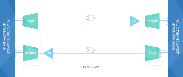
pre-amplifier

Booster Amplifier is installed in the transmitting end of the fiber optic network, which can amplifier amplify the optical signal launched into the fiber link. It is usually used in DWDM network where the multiplexer attenuates the signal channels. The following picture shows a 10G DWDM network using booster amplifier (BA) at the transmitting end and pre-amplifier (PA) at receiving end. Thus, this 10G DWDM network can support a transmission distance much longer than the above-mentioned one. Please note, a DCM (Dispersion Compensation Module) is added in this network to further ensure the transmission quality. A booster amplifier usually provides low gain and high output power.
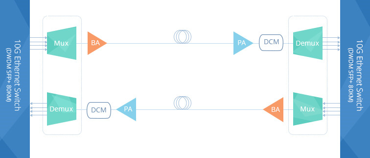
booster amplifier

In-line Amplifier is easy to understand. The gain provided by the pre-amplifier and booster amplifier might not be enough due to the optical loss caused by long haul transmission. In-line amplifier is installed in the fiber optic link every 80-100km as shown in the following picture. It has moderate gain and has similar output power to those of booster amplifier.

in-line amplifier

Conclusion

The optical amplifier can help to amplifier the optical power during long haul transmission to ensure that the receiver can detect the optical signal without error. Three amplifiers are commonly used in DWDM network. Booster amplifier is used to amplifier optical power at the transmitting end and pre-amplifier is placed at the receiver end. If the transmission distance is longer than 150km or have great power loss during transmission, in-line amplifier is suggested to be installed every 80km to 100k in the fiber optic link. The gain of these amplifiers should be carefully calculated during practical use. Kindly visit DWDM EDFA Amplifier page for more details.

Related Article: Introduction of Optical Amplifier

Related Article: Optical Amplifier – EDFA (Erbium-doped Fiber Amplifier) for WDM System

Introduction of Optical Amplifier

With the rapid development of the optic communication networks, longer transmission lengths are required. Optical amplifier can satisfy the requirements of optical communication networks. An optical amplifier is a device that amplifies an optical signal directly, without the need to first convert it to an electrical signal. An optical amplifier may be considered as a laser without an optical cavity, or one in which feedback from the cavity is suppressed. This post is going to help you get a better understanding of optical amplifier.

Working Principles of Optical Amplifier

A basic optical communication link contains a transmitter and receiver, with an optical fiber cable connecting them. Although signals transmitting in optical fiber suffer far less attenuation than in other mediums, such as copper, there is still a limitation about 100 km on the distance the signals can travel before becoming too noisy to be detected.

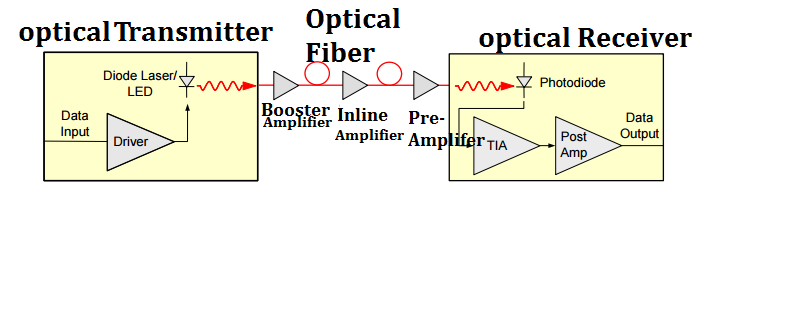
Optical amplifiers are widely used in fiber optic data links. Figure 1 shows three ways in which optical amplifiers can be used to strengthen the performance of optical data links. A booster amplifier is used to increase the optical output of an optical transmitter just before the signal enters an optical fiber. The optical signal is attenuated as it travels in the optical fiber. An inline amplifier is utilized to restore (regenerate) the optical signal to its original power level. An optical pre-amplifier is operated at the end of the optical fiber link in order to increase the sensitivity of an optical receiver.

Optical amplifier in-a-optical-communication-link1

Figure 1. Optical amplifiers  in fiber optic communication links

Features of Optical Amplifier
  • Ratio of output power to input power
  • Gain as a fuction of inpout power
  • Range of wavelengths over which the amplifier is effective
  • Maxmum output power, beyond which no amplification is reached
  • undesired signal due to physical processing in amplifier
Types of Optical Amplifier

There are three most commonly used types of optical amplifiers, as shown from left to right: erbium-doped fiber amplifier, the semiconductor optical amplifier, and the fiber Raman amplifier.

optical amplifiers

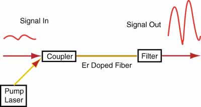
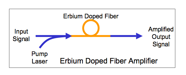
The amplifying medium is a glass optical fiber doped with erbium ions. The erbium is pumped to a state of population inversion with a separate optical input. The erbium-doped glass optical gain medium amplifies light at wavelengths that are in the neighborhood of 1550nm – the optical wavelengths that suffer minimum attenuation in optical fibers. The erbium-doped fiber amplifier (EDFA) is the most deployed fiber amplifier. Erbium-doped optical fiber amplifiers (EDFAs) have low noise and can amplify many wavelengths simultaneously, making the EDFA the amplifier of choice for most applications in optical communications.

erbium-doped fiber amplifier

Figure 2.  Erbium-doped fiber amplifier working principle

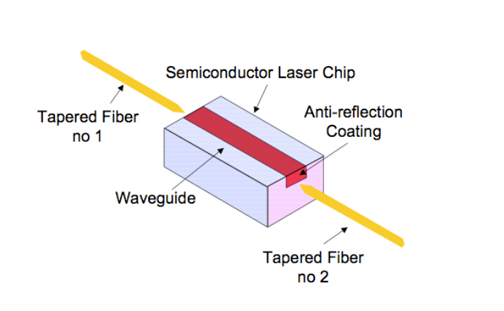
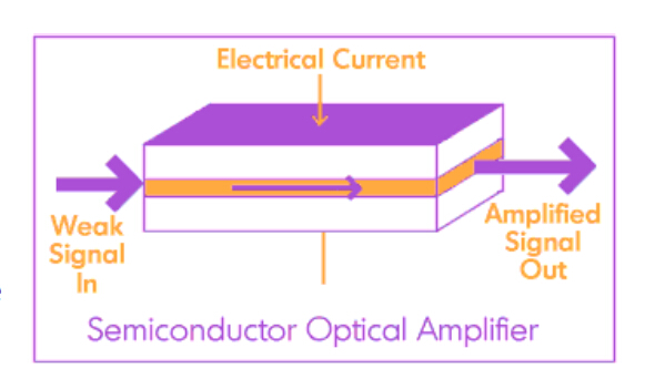
The gain medium is undoped InGaAsP. This material can be tailored to provide optical amplification at wavelengths near 1.3 µm or near 1.5 µm – important wavelengths for optical communications. Other semiconductors can be used to amplify optical signals at other wavelengths. The input and output faces of the amplifier are antireflection coated in order to prevent optical feedback to the gain medium and lasing. Semiconductor Optical Amplifier with its features of small package, low-cost applications and potential use for optical switching, it can be a great choice to suit most customers.

A-semiconductor-optical-amplifier

 Figure 3. Semiconductor optical amplifier working principle

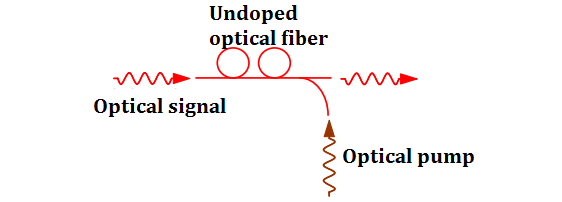
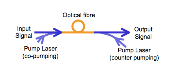
In a Raman amplifier, the signal is intensified by Raman amplification. Unlike the EDFA and SOA the amplification effect is obtained by a nonlinear interaction between the signal and a pump laser within an optical fiber. There are two types of Raman amplifier: distributed and lumped. A distributed Raman amplifier is one in which the transmission fiber is utilized as the gain medium by multiplexing a pump wavelength with signal wavelength, while a lumped Raman amplifier utilizes a dedicated, shorter length of fiber to provide amplification.

A-fiber-Raman-amplifier

Figure 4. Raman amplifier working principle

Conclution

Optical amplifier plays a very important role in modern optical networks, enabling the transmission of many terabits of data over long distances of up to thousands of kilometers. Optical amplifiers provided by Fiberstore are designed for all network segments and applications. For more information please visit fs.com.

Raman Fiber Amplifiers – Advancements to Long Haul Transmission

Introduction

Raman Fiber Amplifier (RFA) is used to assiste optical transmission system design issues such as mid-span optically amplified distance, bandwidth enhancement. The RFA does not suffer from the limitations of Erbium-Doped Fiber Amplifier (EDFA) in that it can be integrated with the transmission fibers, and pumped at any wavelength to provide wide gain bandwidth and gain flatness by employing a combination of different wavelength pumping sources. Offering a number of possible technical advancements to optically amplified long haul transmission infrastructures, RFA has become an achievable possibility in transmission of optical signals.

Configurations of RFA

Different pumping configurations provide flexibility in the system for both distributed and lumped (or discrete) Raman amplifiers.

Distributed Raman Amplifier

Distributed Raman Amplifier (DRA) has emerged in recent years as a key technology for modern optical networks, and especially for coherent transmission. DRA is implemented using Raman pump modules for the counter propagating backward configuration. In this configuration, DRA is most often used in conjunction with conventional EDFA amplifiers, with the Raman pump module serving as a pre-amplifier to the EDFA. In many cases the Raman and EDFA modules are combined into a single hybrid Raman/EDFA module, thus reducing costs, streamlining and optimizing performance, and achieving unified real-time control of both units.

DRA has advantages shown as following:

  1. The gain achievable along the transmission fibers, and ease of gain clamping;
  2. Low noise characteristics;
  3. Better Optical Signal-to-Noise Ratio (OSNR);
  4. Gain non-resonant and could potentially be obtained for any wavelength;
  5. Ultra-wide bandwidth gain of about 6 THz, wide and flat gain bandwidths achievable using multiple pumps at different wavelengths, increased power budget margins.

However, DRA also has some disadvantages:

  1. Very high pump powers required;
  2. Poor pumping efficiency at lower power levels;
  3. Fast response time which results in higher noises;
  4. Severe development for existing fiber system;
  5. Requirement of longer gain fiber;
  6. Severe effects due to nonlinearities.

Lumped Raman Amplifier

It is important to realise while there are some disadvantages to DRA, advancements in fiber technology have been experimented that minimise these issues. A design issue to be considered is the incorporation of Dispersion Compensation Fiber (DCF) into the system model. In this configuration, the Raman amplifier is a Lumped Raman Amplifier (LRA).

In particular, LRA has been considered in long-haul WDM transmission systems. The advantages of LRA include:

  1. High negative dispersion characteristics that could compensate the chromatic and nonlinear dispersion induced in the fiber from Group Velocity Dispersion (GVD) and Self Phase Modulation (SPM).
  2. Small effective area, hence lower pump power, and high Ge impurity concentration in the silica fiber.

However, LRA also has some disadvantages:

  1. Noise can limit the performance of LRA having a gain of more than 15 dB. For smaller fiber lengths the noise figure of the LRA will be at least 3 dB because of the thermal excitation of the vibrational modes.
  2. Noise degrades the OSNR resulting in receiver sensitivity penalty and thus the amplifier gain is limited to some extent for a single LRA.

Fiberstore’s RFA Solution

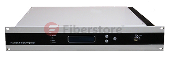
Fiberstore is a world famous company who provides almost all the fiber optic network solutions, including the Raman amplifiers solution. Fiberstore’s Raman Amplifiers have a wide gain spectrum, and the gain bandwidth can be further broadened by the use of multi-wavelength optical pump. After many years of research and network testing, Fiberstore has developed and produced the series of FS-1550 Raman fiber amplifiers, and introduced it to the ultra-long haul optical fiber CATV transmission, specifically in combination with the EDFA applications. The improvement of the indicators of the link is particularly evident, thus get more flat gain spectra and higher OSNR.

Fiberstore's Raman Fiber Amplifier

Note: When choosing an RFA, an important aspect to consider is the on-off Raman gain provided by the amplification. In other words, the gain experienced with Raman in comparison to gain experienced without Raman. The evolution of gain along the total length of the fiber can be solved through the decibel difference. The on-off Raman gain of Fiberstore’s Raman amplifiers covers a range of 6 to 16 dB.

Article Source:  http://www.fiberopticshare.com/raman-fiber-amplifiers-advancements-to-long-haul-transmission.html

Comparison of Different Types of Optical Amplifiers

Optical amplifier is an important technology for optical communication networks. Without the need to first convert it to an electrical signal, the optical amplifiers are now used instead of repeaters. As we know, there are several types of optical amplifiers. Among them, the main amplifier technologies are Doped fiber amplifier (eg. EDFA), Semiconductor optical amplifier (SOA) and Fiber Raman amplifier. Today, we are going to study and compare different types of optical amplifiers in this paper.

Before the comparison of the different types of optical amplifiers, let’s take a closer look at fiber optic amplifier. In general, a repeater includes a receiver and transmitter combined in one package. The receiver converts the incoming optical energy into electrical energy. The electrical output of the receiver drives the electrical input of the transmitter. The optical output of the transmitter represents an amplified version of the optical input signal plus noise. Repeaters do not work for fiber-optic networks, where many transmitters send signals to many receivers at different bit rates and in different formats. However, unlike a repeater, an optical amplifier amplify optical signal directly without electric and electric optical transformation. In addition, an ideal optical amplifier could support multi-channel operation over as wide as possible a wavelength band, provide flat gain over a large dynamic gain range, have a high saturated output power, low noise, and effective transient suppression. Several benefits of optical amplifiers as the following:

  • Support any bit rate and signal format
  • Support the entire region of wavelengths
  • Increase the capacity of fiber-optic links by using WDM
  • Provide the capability of all-optical networks, not just point-to-point links

OK, after a brief introduction of the optical amplifiers, we formally begin today’s main topic. As we talk above, there are three main types of today’s amplifier technology. Each of them has their own working principle, features and applications. We will describe them one by one in the following paragraphs.

Doped fiber amplifier (The typical representative: EDFA)
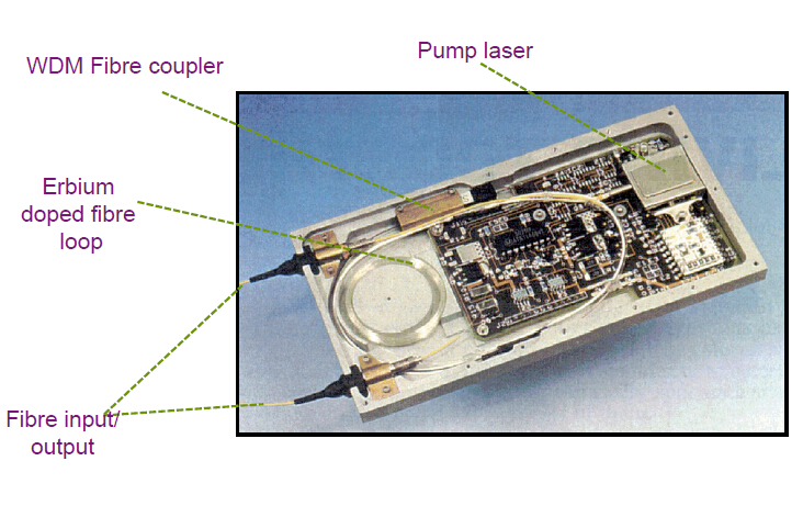
Erbium-doped fiber amplifier (EDFA) is the most widely used fiber-optic amplifiers, mainly made of Erbium-doped fiber (EDF), pump light source, optical couplers, optical isolators, optical filters and other components. Among them, a trace impurity in the form of a trivalent erbium ion is inserted into the optical fiber’s silica core to alter its optical properties and permit signal amplification.

the components of EDFA

Working Principle
The working principle of the EDFA is to use the pump light sources, which most often has a wavelength around 980 nm and sometimes around 1450 nm, excites the erbium ions (Er3+) into the 4I13/2 state (in the case of 980-nm pumping via 4I11/2), from where they can amplify light in the 1.5-μm wavelength region via stimulated emission back to the ground-state manifold 4I15/2.

EDFA

Advantages & Disadvantages of EDFA
Advantages

  • EDFA has high pump power utilization (>50%)
  • Directly and simultaneously amplify a wide wavelength band (>80nm) in the 1550nm region, with a relatively flat gain
  • Flatness can be improved by gain-flattening optical filters
  • Gain in excess of 50 dB
  • Low noise figure suitable for long haul applications

Disadvantages

  • Size of EDFA is not small
  • It can not be integrated with other semiconductor deviecs

Semiconductor optical amplifier (SOA)
Semiconductor optical amplifier is one type of optical amplifier which use a semiconductor to provide the gain medium. They have a similar structure to Fabry–Perot laser diodes but with anti-reflection design elements at the end faces. Unlike other optical amplifiers SOAs are pumped electronically (i.e. directly via an applied current), and a separate pump laser is not required.

design of SOA

Working Principle
1.Stimulated emission to amplify an optical signal.
2.Active region of the semiconductor.
3.Injection current to pump electrons at the conduction band.
4.The input signal stimulates the transition of electrons down to the valence band to acquire an amplification.

SOA

Advantages & Disadvantages of SOA
Advantages

  • The semiconductor optical amplifier is of small size and electrically pumped.
  • It can be potentially less expensive than the EDFA and can be integrated with semiconductor lasers, modulators, etc.
  • All four types of nonlinear operations (cross gain modulation, cross phase modulation, wavelength conversion and four wave mixing) can beconducted.
  • SOA can be run with a low power laser. This originates from the short nanosecond or less upper state lifetime, so that the gain reacts rapidly tochanges of pump or signal power and the changes of gain also cause phase changes which can distort the signals.

Disadvantages
The performance of SOA is still not comparable with the EDFA. The SOA has higher noise, lower gain, moderate polarization dependence and high nonlinearity with fast transient time.

Fiber Raman amplifier (FRA)
Fiber Raman Amplifier (FRA) is also a relatively mature optical amplifier. In a FRA, the optical signal is amplified due to stimulated Raman scattering (SRS). In general, FRA can is divided into lumped type called LRA and distributed type called DRA. The fiber gain media of the former is generally within 10 km. In addition, it requires on higher pump power, generally in a few to a dozen watts that can produce 40 dB or even over gains. It is mainly used to amplify the optical signal band of which EDFA cannot satisfy. The fiber gain media of DRA is usually longer than LRA, generally for dozens of kilometers while pump source power is down to hundreds of megawatts. It is mainly used in DWDM communication system, auxiliarying EDFA to improve the performance of the system, inhibiting nonlinear effect, reducing the incidence of signal power, improving the signal to noise ratio and amplifing online.

Working Principle
The principle of FRA is based on the Stimulated Raman Scattering (SRS) effect. The gain medium is undoped optical fiber. Power is transferred to the optical signal by a nonlinear optical process known as the Raman effect. An incident photon excites an electron to the virtual state and the stimulated emission occurs when the electron de-excites down to the vibrational state of glass molecule. The Stokes shift corresponding to the eigen-energy of a phonon is approximately 13.2 THz for all optical fibers.

FRA

Advantages & Disadvantages of FRA
Advantages

  • Variable wavelength amplification possible
  • Compatible with installed SM fiber
  • Can be used to extend EDFAs
  • Can result in a lower average power over a span, good for lower crosstalk
  • Very broadband operation may be possible

Disadvantages

  • High pump power requirements, high pump power lasers have only recently arrived
  • Sophisticated gain control needed
  • Noise is also an issue

Summary
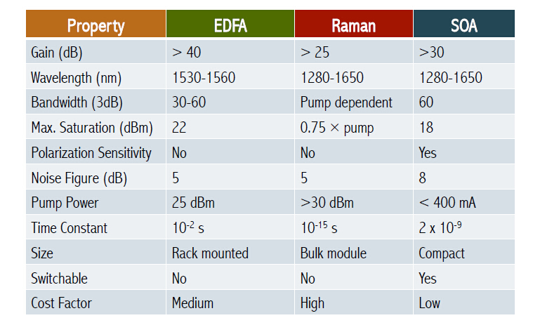
After talking about these three types of optical amplifiers, we make a comparison of them as the following table.

Types of Optical Amplifiers

Related Article: Differences Between Pre-Amplifier, Booster Amplifier and In-line Amplifier

Related Article: Optical Amplifier – EDFA (Erbium-doped Fiber Amplifier) for WDM System