Category Archives: Fiber Cabling

How FS 400G MTP/MPO Cables Enable Efficient Connectivity

400G

The demand for 400G transmission rates by major data centers and telecom carrier continues to grow and cabling solutions are constantly being updated. In order to achieve 400G data rates and save cabling costs, breakthroughs, higher connection density, and simplified network design approaches must be considered, so 400G MTP/MPO cables are becoming more and more common. FS offers MTP/MPO cabling solutions to meet the needs of high-performance 400G networks. This article will describe specific cabling application scenarios.

A Glance at FS 400G MTP/MPO Cables and Transceivers

MTP/MPO cables with multi-core connector are used for optical transceiver connection. There are 4 different types of application scenarios for 400G MTP/MPO cables.

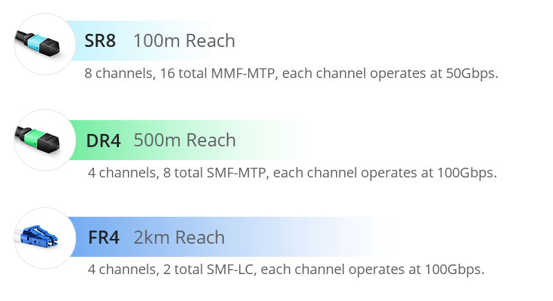
Common MTP/MPO patch cables include 8-fiber, 12-core, and 16-core. 8-core or 12-core MTP/MPO single-mode fiber patch cable is usually used to complete the direct connection of two 400G-DR4 optical transceivers. 16-core MTP/MPO fiber patch cable can be used to connect 400G-SR8 optical transceivers to 200G QSFP56 SR4 optical transceivers, and can also be used to connect 400G-8x50G to 400G-4x100G transceivers. The 8-core MTP to 4-core LC duplex fiber patch cable is used to connect the 400G-DR4 optical transceiver with a 100G-DR optical transceiver.
SR8-vs-DR4-vs-DR8.jpg

Figure 1: SR8-vs-DR4-vs-DR8

FS 400G MTP/MPO Cabling Solutions for Typical 400G Network Applications

As the network upgrades and data centers migrate to 400G rates, how to transition from existing 50G/100G/200G devices to 400G, here are FS MTP/MPO cabling solutions.

400G-400G Direct Connection

500m span with 8-fiber/12-fiber MTP/MPO cable

400G short and medium distance direct connection usually consists of 8-core/12-core MTP patch cable with 400G-DR4 OSFP/QSFP-DD modules. The term “DR4″—”DR” stands for 500m reach using single-mode fiber and “4” implies there are 4 x 100 Gbps optical channels. Since one optical channel requires two fibers, an 8-fiber or a 12-core MTP/MPO cable can be used for the 400G-DR4 module to achieve direct connection. In the 8-fiber MTP cabling, the fiber utilization is 100%, while in the 12-core MTP cabling, four fibers remain unused. Take 400G QSFP-DD module as an example, the following picture is presenting the MTP cabling for 400G DR4 direct connection.

400G-400G Direct Connection Scenario 1.jpg

Figure 2: 400G-400G Direct Connection Scenario 1

PRODUCTSDESCRIPTION
400G DR4 QSFP-DDGeneric Compatible 400G DR4 QSFP-DD PAM4 1310nm 500m DOM Transceiver Module
MTP®-12 (Female) 12 Fibers OS2 Single ModeOS2 Single Mode Elite Trunk Cable, 12 Fibers, Type B, Plenum (OFNP)

100m span with 16-fiber MTP/MPO cable

The 400G-SR8 transceivers require the use of a 16-core MTP cable. The term “SR8” – “SR” stands for a distance of 100 meters using multimode fiber, and “8” implies there exist 8 optical channels with each operating at 50Gbps. In this direct connection, the 16-core MTP cable has 100% fiber utilization. The primary adopters of these 400G-SR8 fiber transceivers are expected to be certain hyperscale cloud service providers in North America and China.

400G-400G Direct Connection Scenario 2.jpg

Figure 3: 400G-400G Direct Connection Scenario 2

PRODUCTSDESCRIPTION
400GBASE-SR8 QSFP-DDGeneric Compatible 400GBASE-SR8 QSFP-DD PAM4 850nm 100m DOM Transceiver Module
MTP®-16 APC (Female) OM4 CableOM4 Multimode Elite Trunk Cable, 16 Fibers, Plenum (OFNP), Magenta, 850/1300nm

400G-2x200G Direct Connection

100m span with 16-fiber MTP conversion cable

In the backbone and some more complex metropolitan area networks, the dual-carrier technology (2x200G) will be adopted to compress the channel spacing compared to a single-carrier 400G technology. Extending the transmission distance and improving the spectral efficiency, 400G-2x200G direct connection can help to deploy 400G backbone networks with minimum bandwidth resources.

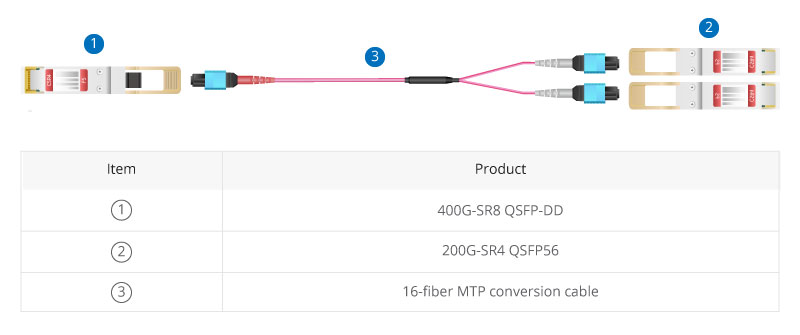
In this case, 16-core MTP conversion cables terminated with MTP/MPO connectors on both ends are needed. With this type of cable, one 400G OFSP/QSFP-DD module and two 200G QSFP56 modules can be directly connected.
400G-2x200G Direct Connection Scenario.jpg

Figure 4: 400G-2x200G Direct Connection Scenario 3

PRODUCTSDESCRIPTION
400GBASE-SR8 QSFP-DDGeneric Compatible 400GBASE-SR8 QSFP-DD PAM4 850nm 100m DOM Transceiver Module
200GBASE-SR4 QSFP56FS for Mellanox MMA1T00-VS Compatible 200GBASE-SR4 QSFP56 850nm 100m DOM Transceiver Module
MTP®-16 APC (Female) OM4 CableOM4 Multimode Elite Trunk Cable, 16 Fibers, Plenum (OFNP), Magenta, 850/1300nm

400G-4x100G Direct Connection

500m span with 8-fiber MTP/MPO trunk cable and 4-LC duplex patch cable

In the 400G to 4x100G migration scenario, an 8-core MTP-LC cassette that packaged in the fiber rackmount enclosure is adopted to realize the transmission from MTP to LC, and then an 8-core MTP/MPO trunk and 4-LC duplex patch cables are used to connect at both ports.

The 400G-4x100G architecture uses four optical modules with 100Gbps wavelengths. However, the current 100G technology is based on a 4x25G design and unable to scale to 400G. 100Gbps per channel can be achieved using PAM4 technology and then aggregated to achieve an overall 400Gbps speed with 4x100G. MTP/MPO cables allow splitting 400G bandwidth into multiple 100G or 40G data streams.

400G-4x100G Direct Connection Scenario.jpg

Figure 5: 400G-4x100G Direct Connection Scenario 4

PRODUCTSDESCRIPTION
400G DR4 QSFP-DDGeneric Compatible 400G DR4 QSFP-DD PAM4 1310nm 500m DOM Transceiver Module
100GBASE-DR QSFP28 Single LambdaGeneric Compatible 100GBASE-DR QSFP28 Single Lambda 1310nm 500m DOM Transceiver Module
MTP® Female to 4 LC UPC Duplex 8 FibersMTP Type B Plenum (OFNP) OS2 9/125 Single Mode Elite Breakout Cable 1310/1550nm
FHD MTP®-8 Cassette to 4x LC Duplex (Blue)8 Fibers OS2 Single Mode, Universal Polarity, MTP® to 4x LC Duplex (Blue), 0.35dB max
Customized 8-144 Fibers MTP®-12OS2 Single Mode Elite Breakout Cable
FHD 144 Fibers (LC) EnclosureFHD High Density 1U Rack Mount Enclosure Unloaded, Tool-less Removable Top Cover, Holds up to 4x FHD Cassettes or Panels

400G-8x50G Direct Connection

500m span with 16-fiber MTP conversion cable and LC duplex patch cable

The rapid growth of 400G has contributed in part to the less popular 50G market, and MTP/MPO cables provide the technology to scale 50GbE to accommodate 400G (8x50G) network. For this scenario example, the MTP cassette is in the middle to connect the 16-core MTP conversion cable and the LC duplex patch cords together to realize the 400G-8x50G direct connection. Eight 50G lanes can support the optical link of 40Gbps aggregation via PAN modulation.

400G-8x50G Direct Connection Scenario.jpg

Figure 6: 400G-8x50G Direct Connection Scenario 5

PRODUCTSDESCRIPTION
400G DR4 QSFP-DDGeneric Compatible 400G DR4 QSFP-DD PAM4 1310nm 500m DOM Transceiver Module
MTP®-16 APC (Female) OM4 CableOM4 Multimode Elite Trunk Cable, 16 Fibers, Plenum (OFNP), Magenta, 850/1300nm
FHD MTP®-24 Cassette to 12x LC Duplex (Aqua)24 Fibers OM4 Multimode, Type A, MTP® to 12x LC Duplex (Aqua), 0.35dB max
MTP®-16 APC (Female) to 8 LC UPC Duplex CableOM4 Multimode Elite Breakout Cable, 16 Fibers, Plenum (OFNP), Magenta,850/1300nm
FHD 144 Fibers (LC) EnclosureFHD High Density 1U Rack Mount Enclosure Unloaded, Tool-less Removable Top Cover, Holds up to 4x FHD Cassettes or Panels

Scaling to FS 400G MTP/MPO Cabling System for 400G Networks

400G is increasingly becoming ubiquitous in many high-performance and high-density networking environments. 400G MTP/MPO cables have been widely used as cabling solutions for 400G network transmission rates due to their unique cabling simplicity and cost reduction benefits. FS offers a wide range of related 400G MTP/MPO cabling products and solutions to smoothly achieve high-speed data transmission.

Original Source: How FS 400G MTP/MPO Cables Enable Efficient Connectivity

5 Types of Optical Fibers for 5G Networks

Optical fiber cables have become one of the key points in the 5G competition. It’s known that 5G networks will offer consumers high-speed and low-latency services with more reliable and stronger connections. But to make this happen, more 5G base stations have to be built due to the higher 5G frequency band and limited network coverage. And it’s estimated that by 2025, the total number of global 5G base stations will reach 6.5 million, which puts forward higher requirements for the optical fiber cable performance and production.

Currently, there are still some uncertainties in 5G network architectures and the selection of technical solutions. But in the basic physical layer, the 5G fiber cables should meet both current application and future development needs. The following are five types of optical fiber cables that address problems in 5G networks built to some degree.

1. Bend Insensitive Optical Fiber for Easy 5G Indoor Micro Base Stations

The dense fiber connections between massive 5G new macro base stations and indoor micro base stations are the main challenge in the 5G access network constructions. The complex cabling environments, especially the indoor fiber cabling, and the limited space and bend request high requirements for the fiber bend performance. Optical fiber compliant ITU G.657.A2/B2/B3 has great bend-improved performance, which can be stapled and bent around corners without sacrificing performance.

Many fiber manufacturers have announced bend-insensitive fiber (BIF) cables with low loss to address such problems in 5G indoor applications.

CompanyProduct NameITU StandardsBend Radius
(1 turn around a mandrel)
Induced Attenuation
(dB)
CorningClearCurve LBL fiberG.652.D, G.657.A2/B27.5 mm≤ 0.4
YOFCEasyBand® Ultra BIFG.652.D, G.657.B35 mm≤ 0.15
Prysmian GroupBendBright XS fiberG.652.D, G.657.A2/B27.5 mm≤ 0.5

Note: The induced attenuation is caused due to fiber wrapped around a mandrel of a specific radius.

2. OM5 Multimode Fiber Applied to 5G Core Networks

5G service providers also have to focus on the fiber optic network build of the data centers where the content is stored. At present, the transmission speed of data centers is evolving from 10G/25G, 40G/I00G to 25G/I00G, 200G/400G, which put forward new requirements for the multimode optical fibers used for interconnection inside the data centers. Multimode optical fibers need to compatible with the existing Ethernet standard, cover the future upgrades to higher speed like 400G and 800G, support multi-wavelength multiplexing technologies like SWDM and BiDi, and also need to provide excellent bending resistance to adjust to dense data centers cabling scenarios.

5g optical fiber cables.jpg

Figure 1: OM5 fiber in 100G BiDi and 100G SWDM applications

Under such conditions, the new broadband OM5 multimode fiber becomes the hotspot option for data center constructions. OM5 fiber allows multiple wavelengths to be transmitted simultaneously in the vicinity of 850 nm to 950 nm. By adopting the PAM4 modulation and WDM technology, OM5 optical fiber is able to support 150 meters in 100Gb/s, 200Gb/s, and 400Gb/s transmission systems, and ensure the ability of future short-distance and high-speed transmission networks, making it the optimal choice for intra-data center connections under the 5G environment.

Fiber TypeEffective Bandwidth (MHz.km)Full injection Bandwidth (MHz.km)
Fiber Type850nm953nm850nm953nm1310nm
OM3>2000/>1500/>500
OM4>4700/>3500/>500
OM5>4700/>35001850>500

Here is a comparison of the link length of OM5 and other multimode fiber over 850nm wavelength.

Link Length (M) @850nm wavelength
Fiber Type10GBASE-SR25GBASE-SR40GBASE-SR4100GBASE-SR4400GBASE-SR16400GBASE-SR8400GBASE-SR4.2
OM330070100701007070
OM4550100150100150100100
OM5550100150100150100150

3. Micron Diameter Optical Fibers Enable Higher Fiber Density

Due to the complex deployment environments of the access layer or aggregation layer of 5G bearer networks, it’s easy to encounter problems like the limited existing cable pipeline resources. To ensure the limited space can hold more optical fibers, cable manufacturers are working hard to reduce the size and diameter of cable bundles. For example, recently the Prysmian Group has introduced the BendBright XS 180µm single-mode fiber to meet the 5G technology demands. This innovative optical fiber enables cable designers to offer strongly reduced cable dimensions while still keeping the 125µm glass diameter.

5G fiber cable.jpg

Figure 2: Prysmian’s BendBright XS 180µm fiber

Similarly, with the same principles, Corning has introduced the SMF-28 Ultra 200 fiber that allows fiber cable manufacturers to shave 45 microns off previous cable coating thicknesses, going from 245 microns down to 200 microns, to achieve a smaller overall outer diameter. And YOFC, another optical fiber manufacturer, also provides EasyBand plus-Mini 200μm reduced diameter bending insensitive fiber for 5G networks, which can reduce the cable diameter by 50% and significantly increase the fiber density in pipelines when compared with common optical fibers.

4. ULL Fiber with Large Effective Area Can Extend 5G Link Length

5G fiber manufacturers are actively exploring ultra low-loss (ULL) optical fiber technologies to extend the fiber reach as long as possible. The G.654.E optical fiber is such a type of innovative 5G fiber. Different from the common G.652.D fiber often used in 10G, 25G, and 100G, the G.652.E fiber comes with a larger effective area and ultra-low loss features, which can significantly reduce the nonlinear effect of optical fiber and improve the OSNR that are easily affected by higher signal modulation format in 200G and 400G connections.

Speed (bps)40G100G400G400G
Fiber Typecommon G.652low-loss G.652low-loss G.652innovative G.654.E
Maximum Capacity (Tbs)3.282020
Limit Relay Distance (km)60003200<800<2000
Typical Link Attenuation (dB/km)0.210.200.200.18
Fiber Effective Area (µm²)808080130

With the continuous increase of the transmission speed and capacity of the 5G core network and the clouded data center, fiber optic cables like this will be needed more. It’s said that the latest Corning’s TXF fiber, a type of G.654.E fiber, comes with high-data-rate capabilities and exceptional reach, able to help network operators deal with growing bandwidth demands while lowering their overall network costs. Recently, Infinera and Corning have achieved 800G across 800km using this TXF fiber, which shows this fiber is expected to offer excellent long-haul transmission solutions for 5G network deployment.

5. Optical Fiber Cable for Faster 5G Network Installation

5G network deployment covers both indoor and outdoor scenarios, the installation speed is a factor needed to consider. Full-dry optical cable using dry water-blocking technology is able to improve fiber splicing speed during cable installation. Air-blown micro cables are compact and lightweight and contain high fiber density to maximize the fiber count. This type of cable is easy to be installed in longer ducts with multiple bends and undulations, and it can save in manpower & installation time and improved installation efficiency via the blowing installation methods. For the outdoor fiber cable deployment, some anti-rodent and anti-bird optical cables also need to be used.

Get Ready for 5G Networks

Currently, optical fiber is the optimal medium capable of scaling to the 5G demands. 5G networks’ enhanced bandwidth capacity, lower latency requirements and complicated outdoor deployments bring challenges as well as unlimited possibilities for optical fiber manufacturers, but our optical networks must quickly adapt to meet such new demands. Except for the optical fiber mentioned above, it remains to be seen if the 5G fiber manufacturers will put forward other innovative fiber for the market as quickly as possible.

Article source: 5 Types of Optical Fibers for 5G Networks

Related Articles:

Challenges and Opportunities of 5G at the Time of COVID-19

CPRI vs eCPRI: What Are Their Differences and Meanings to 5G?

The Infrastructure Bill is all set to transform the Fiber Optic & Data Center Industry

In August 2021, the US Senate passed the Infrastructure Bill to revamp the dated setup responsible for latency issues and low connectivity in underserved rural communities. The bill’s passing has led to great excitement amongst various sectors, chief amongst them being the telecom industry. Here’s an overview of how the Infrastructure Bill will affect the fiber optics and Data Center sectors.

What is the Infrastructure Bill and what does it entail?

The recently approved Infrastructure Bill is set to make considerable headway in bridging the great digital divide: a decade-long problem afflicting some 40 million Americans. The Senate-passed bill of $1.2 trillion hopes to improve the aging American Infrastructure and boost various sectors via increased funding and jobs. $65 billion from this grant is exclusively allocated for enhanced internet experiences in underprivileged regions.

Low bandwidth internet has been creating a great digital divide in various American states for a long time. Communities on the underprivileged side of this divide have suffered from maladjustment in the new virtual norm. Poor connectivity for these communities has meant inefficiency in carrying out routine tasks, failure in maintaining uninterrupted workflows, and severed communications. Digital solutions that have become part and parcel of many Americans, such as e-learning, telehealth, etc., are still somewhat of an anomaly for these regions.

America needs a rejuvenated infrastructure that enables these communities with a secure, high-quality, and super-fast connection.

The bill’s passage is said to remove these barriers in the underserved regions. However, this will also call for a joint deliverance from all parties involved, including government bodies, the telecommunications industry, and the fiber optics/ data center sectors. These are major sectors poised to help America close the great digital divide and successfully make the virtual shift.

How will this bill affect the fiber optics and data center sector?

One of the major components of this project is the expansion of the internet infrastructure. This, along with effectively and efficiently building out in remote regions while eliminating inconsistent right-of-way rules, will result in adequate and speedy connections. There are many other complexities involved, but what the underprivileged communities, such as the Midwest, need most are 5G wireless services and robust fiber deployment.

Telecommunications and Data Center industries have always found infrastructure expansion difficult in places such as the Midwest due to natural physical barriers. These include the largely uneven landscape of mountains, roughly-cleared forests, and expanses of water. All of these have led to poor internet connections in these regions. Introducing the 5G wireless service can be a great way to overcome the handicaps of nature. But setting up these services would require vigorous fiber optic cable deployments and construction of powerful data centers.

The fiber optics sector is the chief component against which the entire digital network is buttressed. This is the network of speedy internet and empowered consumers who are facilitated 24/7 with high-quality, uninterrupted connections and modern digital services.

Modern digital services rely heavily on network densification and evolving technologies such as the blockchain, AI, and the IoT. Fiber optics is responsible for supporting most of these modernized services. Network densification is an efficient way to increase network capacity without requiring more rack space, but this also means constructing a large number of data centers in these areas.

To make the 5G technology work, the fiber optics industry will have to build data centers and cell towers in close proximity to eliminate latency problems through agile deployment. This 5G wireless fiber-based network of data centers will provide these remote regions with the resiliency and scaling needed to maintain critical speeds and higher bandwidths.

This kind of networking will also require all stakeholders, network enterprises, and local government bodies to work together and ensure that all populations can derive massive benefits from the revamped Infrastructure.

The federal government has already taken various initiatives to maximize funding for quicker broadband infrastructure deployment and more can be added to the allocated amount in the coming years. The National Digital Inclusion Alliance reported on the number of measures taken by the government to improve the digital literacy efforts and bring together pockets of communities via a compact digital resource network. As these state and federal-backed initiatives help overcome problems of connectivity caused by physical barriers, underserved populations will finally access reliable connectivity.

Some potential pitfalls to watch out for with the Infrastructure Bill

While there is a great buzz surrounding the opportunities and innovations stemming from the bill’s passing, there are some potential pitfalls that both governments and industry enterprises must look out for.

The prospect of billions in federal grants means that multiple telecommunication and fiber optics enterprises will be vying for the funds. If too many telecoms in one region get access to the federal grant, the result could be an overbuilding of the digital infrastructure. This may put an excessive burden on the electrical energy sector and cause other environmental hazards.

It is also feared that the grant will keep new tech companies at bay by providing already established tech enterprises access to rural areas. The result could be a stifling of innovations in broadband internet technology.

The future of fiber optics and datacenter sector post-Infrastructure Bill

The 5G fiber technology offers the fastest internet connectivity helping businesses set greater targets and achieve better results. With the release of grants from the federal government, the industry will undoubtedly expand to accommodate the growing need for innovative solutions.

According to one study, the fiber industry will grow at 8.5% in the coming years. By 2025, the fiber optics sector is estimated to become a seven billion-dollar industry.

Numerous cities plan for a fiber-based internet network to create what Wired news calls the “internet utopia”. An ambitious network provider has already planned for an 8000-mile long submarine underwater fiber optic cable connecting Los Angeles and Hong Kong to support the increasing demand for Google and Facebook.

There is a great buzz surrounding the expansion of the 5G wireless network and what it means for the great virtual shift in the country. It will not be long before we begin seeing the role of fiber optics and data centers in newer, modern, and diversified digital applications and devices accessible by all.

Article Source: The Infrastructure Bill is all set to transform the Fiber Optic & Data Center Industry

Related Articles:

5 Types of Optical Fibers for 5G Networks

What Is Data Center Security?

Interconnect and Cross Connect in Data Center

As massive amounts of data are transferred and stored across the globe, many organizations are placing greater emphasis on network performance to provide great customer service and build a fast and reliable network for their employees. Improving network connectivity in data centers is one of the most basic and critical ways to optimize network and hybrid architecture. When it comes to the connection between the horizontal cabling and active equipment such as switches, there are two basic configurations that are interconnect and cross connect.

Interconnect and Cross Connect Basics

Interconnect in data center is to use a patch panel on the active equipment to distribute links from device to other devices in the data center, commonly known as the distribution panel. In an interconnect system, patching is done directly between the active equipment and the distribution patch panel. More specifically, outlets are terminated to a patch panel, and the patch panel is then patched directly to a switch, as shown in the figure below.

Interconnect
Interconnect

A cross connect in data center is the use of additional patch panels to mirror the ports of the equipment being connected, essentially creating a separate patching zone that provides connection between different equipment by patch cords. In a cross-connect system, the switch ports are replicated on the additional patch panel, also called equipment patch panel, and patching is carried out between the equipment patch panel and the distribution patch panel. Basically, there are two types of cross-connects, which are three-connector cross-connect and four-connector cross connect.

The structure of a three-connector cross connect is similar to interconnect mentioned above, just adding a cross-connecting process at the switch end, as shown below.

Three-Connector Cross Connect

Four-connector cross connect usually requires a patch field which is usually an individual cabinet. In this case, two copper trunk cables are working as permanent cables, making the cabling system easier to manage.

Four-Connector Cross Connect

Interconnect Vs Cross Connect: How to Choose?

Currently, most cabling systems use interconnect design. But some people indicate the cross connect is preferred as it increases the reliability of the system. Choosing the right cabling system should be based on the needs of data center connectivity combining these two systems’ cost, security and management, as discussed below.

Costs

The cross connect design doubles the number of patch panels needed, which obviously requires more cabling and connectivity, and places more connectivity points (and therefore insertion loss) into a channel. Therefore, an interconnect design is quicker, easier and cheaper to deploy than a cross connect design and provides better transmission performance.

Security

A cross connect cabling involves a dedicated patching area that isolates mission-critical active equipment away from the passive patch zone, thus preventing any tampering with sensitive equipment ports during routine maintenance. Therefore, the cross connect design can improve reliability as it reduces misoperations and ensures fast fault recovery.

Management

Compared to interconnect systems, the cross connect design offers prominent advantages in management. In a cross connect system, the cables connected to switches and servers can be fixed and regarded as permanent connections. When moves, additions, and replacements are required, maintenance personnel only need to change the jumpers between patch panels, whereas it is inevitable to plug and remove the cables of the switch and server ports in interconnect systems. However, even though the interconnect system does not have a dedicated patching area to simplify management, it requires less rack space, which may be favored by communication rooms with limited space.

Conclusion

Cross connect design doubles patch panels and requires more cabling and connectivity than interconnect design, resulting in more rack space and significantly higher costs, but it simplifies management and improves reliability for data centers. Organizations can choose the right cabling system based on their actual situation and needs.

Article Source: Interconnect and Cross Connect in Data Center

Related Articles:

Data Center Pre-terminated Copper Trunk Cable Solution

Data Center Architecture Design: Top of Rack vs End of Row

10G SFP+ and 25G SFP28 Compatibility Analysis

In recent years, data centers are expanding at an unprecedented pace to drive the need for increasing bandwidth between the server and switches. 10GbE is not adequate bandwidth for today’s networks. There’s a tendency that 25GbE (based on SFP28) is on route to displace 10GbE (based on SFP+) from its leading role as the work horse in networking construction. As this transition takes place, questions about SFP+ and SFP28 compatibility arise for anyone who’s planning to upgrade the 10GbE to the higher and faster 25GbE. This post will provide a thorough presentation to 25GbE and clarify the compatibility issues between 10G SFP+ and 25G SFP28.

What Is 25G and Why Do We Need It?

25G Ethernet was based on the IEEE 802.3by standard and released in 2016. 25GbE specification makes use of single-lane 25 Gbps Ethernet links, providing a simpler path to future Ethernet speeds of 50 Gbps, 100 Gbps and beyond. By offering the advantages listed below, 25GbE is gained more and more momentum among service providers and data centers.

Backward Compatibility With 10GbE

The high performance 25G chips use single-lane 25G serdes technology similar in operation to 10GbE, supporting technology advancements from 10G in packaging and silicon. 25GbE allows existing switch architectures to support link speeds faster than 10G with no increase in cable/ trace interconnect.

Faster Network Performance

The 25G Ethernet based on the SFP28 form factor delivers 2.5 times more performance and bandwidth compared to 10G speeds. It also provides easy migration path to 50GE (2x25GE) & 100GE (4x25G), laying a path to higher networking speeds like 200G and 400G.

Significant Cost Benefits

25GbE delivers 2.5 times more data vs. 10GbE, thus reducing the power and cost per gigabit significantly. This power savings will in turn result in lower cooling requirements and operational expenditure for data center operators.

Available 25G Optical Modules and Cables

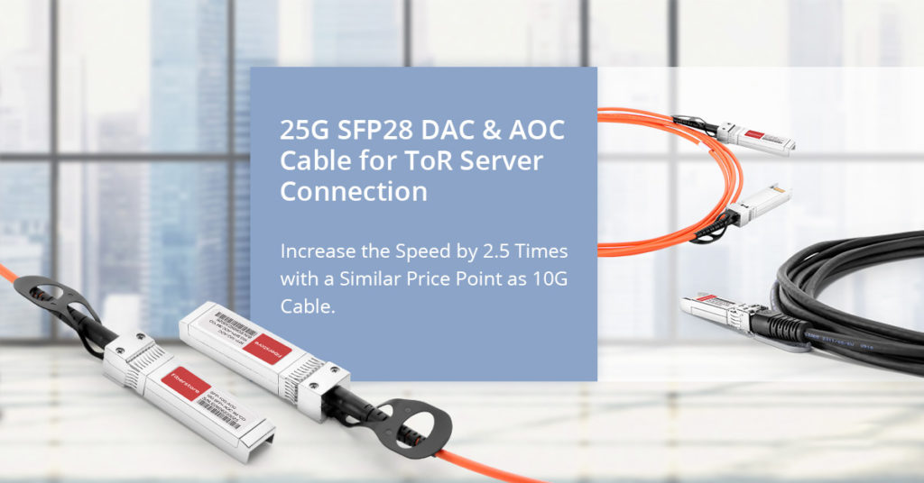
Every new Ethernet speed has gone through multiple pluggable form factor migrations to achieve higher density and lower power consumption goals. For instance, 10G moved successively to the X2 and XFP form factors before finally converging on the SFP+ form factor that allows for up to 48 ports per 1U. Similar form factor transitions happened for 40G (CFP to QSFP) and 100G (CFP, CFP2, CFP4 and QSFP), in achieving the highest density and lowest power. With the release of the 25GbE specification, 25 Gigabit Ethernet equipment is available on the market using the SFP28 form factors. For optical modules, FS offers cost-effective 25GBASE-SR, 25GBASE-LR, and 25G CWDM SFP28 transceivers to cut your hardware costs. For short-haul transmission, 25G SFP28 DAC (direct attach cable) and 100G QSFP28 to 4x SFP28 AOC (active optical cable) in various lengths are also available for all needs and specifications.

25G SFP28 DAC and AOC

10G SFP+ and 25G SFP28 Compatibility

With 10G and 25G Ethernet equipment coexisting on the market today, we may frequently encounter the compatibility issues related to SFP+ and SFP28 form factors. Anyway, the newer 25GbE technologies are backward compatible with 10GbE, allowing customers to build and cross-connect a heterogeneous-speed Ethernet network. Here we list the frequently asked questions coming through average customers.

1.What is the difference between SFP28 and SFP+?

The pinouts of SFP28 and SFP+ connectors are mating compatible. However, SFP+ is designed to operate at speed up to 10 Gb/s whereas SFP28 can handle 25Gbps, 10Gbps and even 1Gbps. SFP28 has increased bandwidth, superior impedance control and less crosstalk than the SFP+ solution. Besides, the SFP28 copper cable has significantly greater bandwidth and lower loss compared to the SFP+ version.

2.Can the SFP28 be used in SFP+ slot, and what speed will I get?

Theoretically, plugging an SFP28 transceiver or cable into the 10G interface is feasible for certain devices to get 10Gb/s data rate, but this solution is not recommended, because it would be limited by the NIC and switch port that you have. Only when your SFP28 module is 100% compatible with your server or switch can you ensure that the links can go seamlessly and efficiently.

3.Can the SFP+ be used in SFP28 slot, and what speed will I get?

Theoretically, plugging an SFP+ transceiver or cable into the 25G SFP28 slot is feasible. But you also need to make sure ensure that your existing modules will be compatible with your switch gear. That is to say, although a switch that accepts the SFP28 form factor can physically accept a SFP+ connector in the same port, it doesn’t mean that your SFP+ modules will work on your equipment.

Note: When shopping for new 25G leaf switches, if you have SFP+ modules you want to use, look for switches that accept the SFP28 form factor, which is physically capable of taking existing SFP+ modules. The same holds true for QSFP+ modules and QSFP28 ports. Carefully read the product specs to ensure that your existing modules will work with your new equipment.

Conclusion

As the majority of 25G switches and network interface cards offer backward compatibility to 10G, there is lots of flexibility to manage a gradual migration to higher speed servers and mix and match port speeds. Theoretically, all SFP28 based 25G ports on switches and 25G NICs can be used at 10G speed via port self-negotiation, but the premise should be that your existing modules are compatible with the NIC and switch port that you have. With a minimal premium for 25G based systems compared to 10G systems, it becomes a wise choice to deploy 25G capable systems to realize the performance advantages for migrations & future proofing initiatives.

Related Article:
10G – 25G – 100G Network Upgrade: An Inevitable Roadmap for Future Data Centers
FS 25G Portfolio for Data Center 25G/100G Leaf-Spine Network