Tag Archives: MPO/MTP cables

How FS 400G MTP/MPO Cables Enable Efficient Connectivity

400G

The demand for 400G transmission rates by major data centers and telecom carrier continues to grow and cabling solutions are constantly being updated. In order to achieve 400G data rates and save cabling costs, breakthroughs, higher connection density, and simplified network design approaches must be considered, so 400G MTP/MPO cables are becoming more and more common. FS offers MTP/MPO cabling solutions to meet the needs of high-performance 400G networks. This article will describe specific cabling application scenarios.

A Glance at FS 400G MTP/MPO Cables and Transceivers

MTP/MPO cables with multi-core connector are used for optical transceiver connection. There are 4 different types of application scenarios for 400G MTP/MPO cables.

Common MTP/MPO patch cables include 8-fiber, 12-core, and 16-core. 8-core or 12-core MTP/MPO single-mode fiber patch cable is usually used to complete the direct connection of two 400G-DR4 optical transceivers. 16-core MTP/MPO fiber patch cable can be used to connect 400G-SR8 optical transceivers to 200G QSFP56 SR4 optical transceivers, and can also be used to connect 400G-8x50G to 400G-4x100G transceivers. The 8-core MTP to 4-core LC duplex fiber patch cable is used to connect the 400G-DR4 optical transceiver with a 100G-DR optical transceiver.
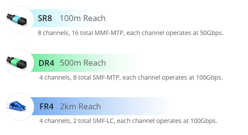
SR8-vs-DR4-vs-DR8.jpg

Figure 1: SR8-vs-DR4-vs-DR8

FS 400G MTP/MPO Cabling Solutions for Typical 400G Network Applications

As the network upgrades and data centers migrate to 400G rates, how to transition from existing 50G/100G/200G devices to 400G, here are FS MTP/MPO cabling solutions.

400G-400G Direct Connection

500m span with 8-fiber/12-fiber MTP/MPO cable

400G short and medium distance direct connection usually consists of 8-core/12-core MTP patch cable with 400G-DR4 OSFP/QSFP-DD modules. The term “DR4″—”DR” stands for 500m reach using single-mode fiber and “4” implies there are 4 x 100 Gbps optical channels. Since one optical channel requires two fibers, an 8-fiber or a 12-core MTP/MPO cable can be used for the 400G-DR4 module to achieve direct connection. In the 8-fiber MTP cabling, the fiber utilization is 100%, while in the 12-core MTP cabling, four fibers remain unused. Take 400G QSFP-DD module as an example, the following picture is presenting the MTP cabling for 400G DR4 direct connection.

400G-400G Direct Connection Scenario 1.jpg

Figure 2: 400G-400G Direct Connection Scenario 1

PRODUCTSDESCRIPTION
400G DR4 QSFP-DDGeneric Compatible 400G DR4 QSFP-DD PAM4 1310nm 500m DOM Transceiver Module
MTP®-12 (Female) 12 Fibers OS2 Single ModeOS2 Single Mode Elite Trunk Cable, 12 Fibers, Type B, Plenum (OFNP)

100m span with 16-fiber MTP/MPO cable

The 400G-SR8 transceivers require the use of a 16-core MTP cable. The term “SR8” – “SR” stands for a distance of 100 meters using multimode fiber, and “8” implies there exist 8 optical channels with each operating at 50Gbps. In this direct connection, the 16-core MTP cable has 100% fiber utilization. The primary adopters of these 400G-SR8 fiber transceivers are expected to be certain hyperscale cloud service providers in North America and China.

400G-400G Direct Connection Scenario 2.jpg

Figure 3: 400G-400G Direct Connection Scenario 2

PRODUCTSDESCRIPTION
400GBASE-SR8 QSFP-DDGeneric Compatible 400GBASE-SR8 QSFP-DD PAM4 850nm 100m DOM Transceiver Module
MTP®-16 APC (Female) OM4 CableOM4 Multimode Elite Trunk Cable, 16 Fibers, Plenum (OFNP), Magenta, 850/1300nm

400G-2x200G Direct Connection

100m span with 16-fiber MTP conversion cable

In the backbone and some more complex metropolitan area networks, the dual-carrier technology (2x200G) will be adopted to compress the channel spacing compared to a single-carrier 400G technology. Extending the transmission distance and improving the spectral efficiency, 400G-2x200G direct connection can help to deploy 400G backbone networks with minimum bandwidth resources.

In this case, 16-core MTP conversion cables terminated with MTP/MPO connectors on both ends are needed. With this type of cable, one 400G OFSP/QSFP-DD module and two 200G QSFP56 modules can be directly connected.
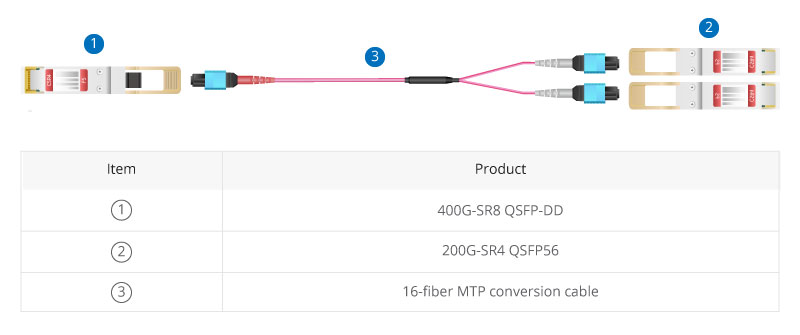
400G-2x200G Direct Connection Scenario.jpg

Figure 4: 400G-2x200G Direct Connection Scenario 3

PRODUCTSDESCRIPTION
400GBASE-SR8 QSFP-DDGeneric Compatible 400GBASE-SR8 QSFP-DD PAM4 850nm 100m DOM Transceiver Module
200GBASE-SR4 QSFP56FS for Mellanox MMA1T00-VS Compatible 200GBASE-SR4 QSFP56 850nm 100m DOM Transceiver Module
MTP®-16 APC (Female) OM4 CableOM4 Multimode Elite Trunk Cable, 16 Fibers, Plenum (OFNP), Magenta, 850/1300nm

400G-4x100G Direct Connection

500m span with 8-fiber MTP/MPO trunk cable and 4-LC duplex patch cable

In the 400G to 4x100G migration scenario, an 8-core MTP-LC cassette that packaged in the fiber rackmount enclosure is adopted to realize the transmission from MTP to LC, and then an 8-core MTP/MPO trunk and 4-LC duplex patch cables are used to connect at both ports.

The 400G-4x100G architecture uses four optical modules with 100Gbps wavelengths. However, the current 100G technology is based on a 4x25G design and unable to scale to 400G. 100Gbps per channel can be achieved using PAM4 technology and then aggregated to achieve an overall 400Gbps speed with 4x100G. MTP/MPO cables allow splitting 400G bandwidth into multiple 100G or 40G data streams.

400G-4x100G Direct Connection Scenario.jpg

Figure 5: 400G-4x100G Direct Connection Scenario 4

PRODUCTSDESCRIPTION
400G DR4 QSFP-DDGeneric Compatible 400G DR4 QSFP-DD PAM4 1310nm 500m DOM Transceiver Module
100GBASE-DR QSFP28 Single LambdaGeneric Compatible 100GBASE-DR QSFP28 Single Lambda 1310nm 500m DOM Transceiver Module
MTP® Female to 4 LC UPC Duplex 8 FibersMTP Type B Plenum (OFNP) OS2 9/125 Single Mode Elite Breakout Cable 1310/1550nm
FHD MTP®-8 Cassette to 4x LC Duplex (Blue)8 Fibers OS2 Single Mode, Universal Polarity, MTP® to 4x LC Duplex (Blue), 0.35dB max
Customized 8-144 Fibers MTP®-12OS2 Single Mode Elite Breakout Cable
FHD 144 Fibers (LC) EnclosureFHD High Density 1U Rack Mount Enclosure Unloaded, Tool-less Removable Top Cover, Holds up to 4x FHD Cassettes or Panels

400G-8x50G Direct Connection

500m span with 16-fiber MTP conversion cable and LC duplex patch cable

The rapid growth of 400G has contributed in part to the less popular 50G market, and MTP/MPO cables provide the technology to scale 50GbE to accommodate 400G (8x50G) network. For this scenario example, the MTP cassette is in the middle to connect the 16-core MTP conversion cable and the LC duplex patch cords together to realize the 400G-8x50G direct connection. Eight 50G lanes can support the optical link of 40Gbps aggregation via PAN modulation.

400G-8x50G Direct Connection Scenario.jpg

Figure 6: 400G-8x50G Direct Connection Scenario 5

PRODUCTSDESCRIPTION
400G DR4 QSFP-DDGeneric Compatible 400G DR4 QSFP-DD PAM4 1310nm 500m DOM Transceiver Module
MTP®-16 APC (Female) OM4 CableOM4 Multimode Elite Trunk Cable, 16 Fibers, Plenum (OFNP), Magenta, 850/1300nm
FHD MTP®-24 Cassette to 12x LC Duplex (Aqua)24 Fibers OM4 Multimode, Type A, MTP® to 12x LC Duplex (Aqua), 0.35dB max
MTP®-16 APC (Female) to 8 LC UPC Duplex CableOM4 Multimode Elite Breakout Cable, 16 Fibers, Plenum (OFNP), Magenta,850/1300nm
FHD 144 Fibers (LC) EnclosureFHD High Density 1U Rack Mount Enclosure Unloaded, Tool-less Removable Top Cover, Holds up to 4x FHD Cassettes or Panels

Scaling to FS 400G MTP/MPO Cabling System for 400G Networks

400G is increasingly becoming ubiquitous in many high-performance and high-density networking environments. 400G MTP/MPO cables have been widely used as cabling solutions for 400G network transmission rates due to their unique cabling simplicity and cost reduction benefits. FS offers a wide range of related 400G MTP/MPO cabling products and solutions to smoothly achieve high-speed data transmission.

Original Source: How FS 400G MTP/MPO Cables Enable Efficient Connectivity

Understanding MPO Cable and Polarity

MPO/MTP technology, which is of high density, flexibility and reliability with scalable, upgradeable properties, is one of the contributors that lead the migration to 40/100GbE. However, the network designers face another challenge which is how to assure the proper polarity of these array connections using multi-fiber MPO/MTP components from end-to-end. Maintain the correct polarity across a fiber network ensures that a transmit signal from any type of active equipment will be directed to receive port of a second piece of active equipment – and vice versa. To ensure the MPO cable work with correct polarity, the TIA 568 standard provided three methods, which will be introduced in this article.

MPO Connector

To understand the polarity in 40/100 GbE Transmission, the key of MPO technology—MPO cable connector should be first introduced. MPO connector usually has 12 fibers. 24 fibers, 36 fibers and 72 fibers are also available. Each MTP connector has a key on one of the flat side added by the body. When the key sits on the bottom, this is called key down. When the key sits on top, this is referred to as the key up position. In this orientation, each of the fiber holes in the connector is numbered in sequence from left to right and is referred as fiber position, or P1, P2, etc. A white dot is additionally marked on one side of the connector to denote where the position 1 is. (shown in the following picture) The orientation of this key also determines the MPO cable polarity.

MPO cable connector

Three Cables for Three Polarization Methods

The three methods for proper polarity defined by TIA 568 standard are named as Method A, Method B and Method C. To match these standards, three type of MPO truck cables with different structures named Type A, Type B and Type C are being used for the three different connectivity methods respectively. In this part, the three different cables will be introduced firstly and then the three connectivity methods.

MPO Trunk Cable Type A: Type A cable also known as straight cable, is a straight through cable with a key up MPO connector on one end and a key down MPO connector on the opposite end. This makes the fibers at each end of the cable have the same fiber position. For example, the fiber located at position 1 (P1) of the connector on one side will arrive at P1 at the other connector. The fiber sequence of a 12 fiber MPO Type A cable is showed as the following:

Type A MTP Cable

MPO Trunk Cable Type B: Type B cable (reversed cable) uses key up connector on both ends of the cable. This type of array mating results in an inversion, which means the fiber positions are reversed at each end. The fiber at P1 at one end is mated with fiber at P12 at the opposing end. The following picture shows the fiber sequences of a 12 fiber Type B cable.

Type B cable

MPO Trunk Cable Type C: Type C cable (pairs flipped cable) looks like Type A cable with one key up connector and one key down connector on each side. However, in Type C each adjacent pair of fibers at one end are flipped at the other end. For example, the fiber at position 1 on one end is shifted to position 2 at the other end of the cable. The fiber at position 2 at one end is shifted to position 1 at the opposite end etc. The fiber sequence of Type C cable is demonstrated in the following picture.

Type C Cable

Three Connectivity Methods

Different polarity methods use different types of MTP trunk cables. However, all the methods should use duplex patch cable to achieve the fiber circuit. The TIA standard also defines two types of duplex fiber patch cables terminated with LC or SC connectors to complete an end-to-end fiber duplex connection: A-to-A type patch cable—a cross version and A-to-B type patch cable—a straight-through version.

Duplex patch cable

The following part illustrates how the components in MPO system are used together to maintain the proper polarization connectivity, which are defined by TIA standards.

Method A: the connectivity Method A is shown in the following picture. A type-A trunk cable connects a MPO module on each side of the link. In Method A, two types of patch cords are used to correct the polarity. The patch cable on the left is standard duplex A-to-B type, while on the right a duplex A-to-A type patch cable is employed.

Method A

Method B: in Connectivity Method B, a Type B truck cable is used to connect the two modules on each side of the link. As mentioned, the fiber positions of Type B cable are reversed at each end. Therefore standard A-to-B type duplex patch cables are used on both sided.

Method B

Method C: the pair-reversed trunk cable is used in Method C connectivity to connect the MPO modules one each side of the link. Patch cords at both ends are the standard duplex A-to-B type.

Method C

Conclusion

Network designer using MPO/MTP components to satisfy the increasing requirement for higher transmission speed, during which one of the big problems—polarity, can be solved by selecting the right types of MPO cables, MPO connectors, MPO cassette and patch cables. The three different polarization methods can be applied according to the satisfy requirements in different situations. For more information about polarity in MPO systems and 40/100GbE transmission polarity solutions, please visit Fiberstore tutorial at “Polarity and MPO Technology in 40/100GbE Transmission“.

Related articles: Understanding Polarity in MPO System

                             Introduction to MTP Connector and MPO Connector

MPO/MTP Assemblies Are Ready to Greet The Future of Data Center

Rapid growth of bandwidth promotes development of data center, which drives the MPO/MTP cables providing cost-effective and efficient way to greet the future of data center. IEEE 802.3ba, the standard for implementing 40/100G Ethernet, dictates that the MPO/MTP footprint will be the standard for multi-mode transmission. This assures the MPO/MTP connector will be the future of optical transmission in the data center for the next few generations to come.

A data center, as defined in TIA/EIA-942, Telecommunications Infrastructure Standard for Data Centers, is a building or portion of a building whose primary function is to house a computer room and its support areas. The main functions of a data center are to centralize and consolidate information technology (IT) resources, house network operations, facilitate e-business and to provide uninterrupted service to mission-critical data processing operations. Yes, it is what we used to call the computer room before it grew to fill buildings. It’s easy to understand but hard to comprehend how much data is being uploaded and downloaded every second on the Internet. The following pictures will show you how big Google data center is.

Google-DS-smdata-center

Due to every data center begins with fiber optic connections to the Internet. Thus, the type of cable connectors becomes the first thing to consider. Which type will be the priority to support such big data transmission? The answer is MPO/MTP connector, because the MPO/MTP connector offers ideal solutions for setting up high-performance data networks in data centers to meet future requirements. The MPO/MTP connector (known as multi-fiber push-on and also as multi-path push-on) can accommodate up to 72 fibers in the tiniest of spaces. MPO/MTP cables can bridge legacy 1Gbps/10Gbps networks over to 40Gbps/100Gbps networks, and can act as the trunk line on a network backbone. There are various types of MPO/MTP cables, such as, trunk cables, harness cables and cassettes. Among these cables, trunk cables are unique and useful due to following features and advantages.

Fiber trunk cables are typically 12-144 fibers and create the permanent fiber links between patch panels in a structured environment. They are pre-terminated from the manufacturer with MPO/MTP Connectors at a specified length and have a pulling grip for easy installation.

Trunk cable has the following advantages:

  • Higher quality—Trunk cable can achieve higher quality with factory termination and testing of each individual product.
  • Minimal skew—The skew can be measured and minimized with factory-terminated trunk cables.
  • Shorter installation time—The pre-terminated MPO/MTP cable system can be incorporated and immediately plugged in with its plug and play design. This design greatly reduces the installation time.
  • Better protection—All termination is done in the factory, so cables and connectors are completely protected from ambient influences. Fiber optic lines lying about in the open in splice trays are exposed at least to the ambient air and may age more rapidly as a result.
  • Smaller volume of cable—Smaller diameters can be achieved in the production of MPO/MTP  cabling from fiber optic loose tube cables.
  • Lower total costs—In splice solutions, splicing including much time and equipment, such as, skilled labor, meters of cable, pigtails, splice trays, splice protection and holders. By comparison, pre-terminated trunk cables not only have technical advantages but also usually involve lower total costs than splice solutions.

MPO/MTP trunk cable is designed for high density application which offers excellent benefits in installation time and space saving. With its features and advantages, MPO/MTP trunk cable is ready to greet the future of data center. Definitely, there will be increasing demand of big data in the next few generations of data center. The ultimate goal of MPO/MTP trunk cable is to keep pace with the rapid development of data center.