Tag Archives: CWDM SFP

Embedded CWDM Solution for Fiber Channel SAN Extension

CWDM, as an established optical transport technology, is universally employed in optical network for transmission distance extension and fiber exhaust reduction. This technology has evolved for years and now is available for Fiber Channel applications with the rate up to 4.25Gb/s. Moreover, when compared with traditional transmission approach via multiple fibers, embedded CWDM technology also makes economic sense while used in 4G Fiber Channels, and that’s what we are going to address in this article.

Fiber Channel Overview

The 4G Fiber Channel effectively improves storage area networks (SANs) performance by doubling speed and offering backward compatibility with 2G and 1G systems. With the proliferation of bandwidth-extensive applications, fiber capacity is on the edge of exhaustion. However, the demand for extremely high-capacity data transmissions began to soar. In this case, it is critical for IT technicians to enhance Fiber Channel SAN capacity without increasing costs.

Economical Fiber Channel Solution: Embedded CWDM Technology

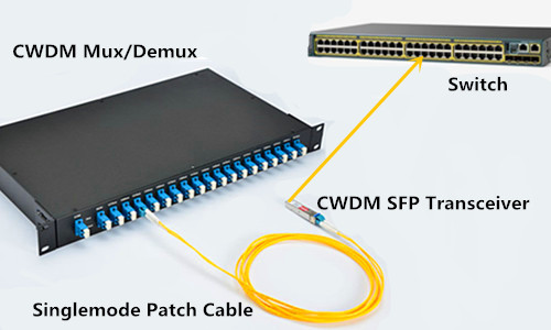
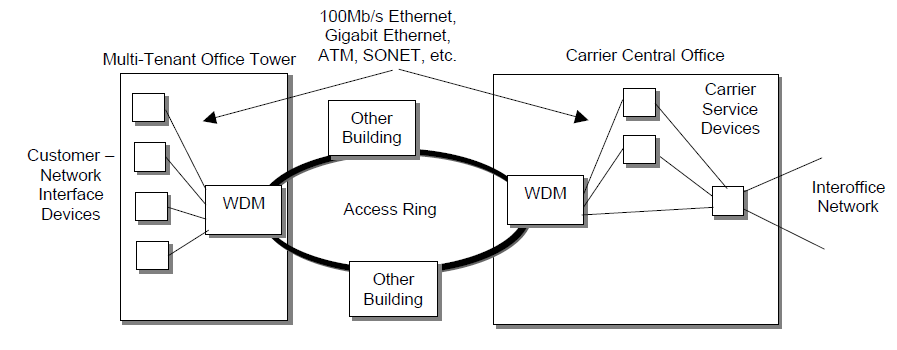
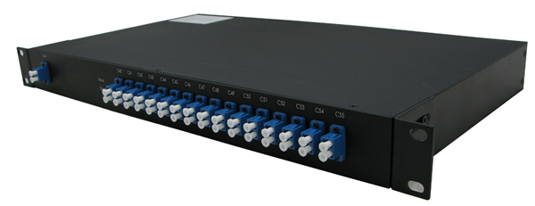
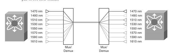
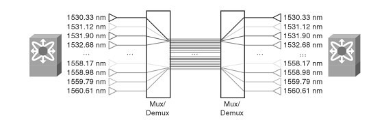
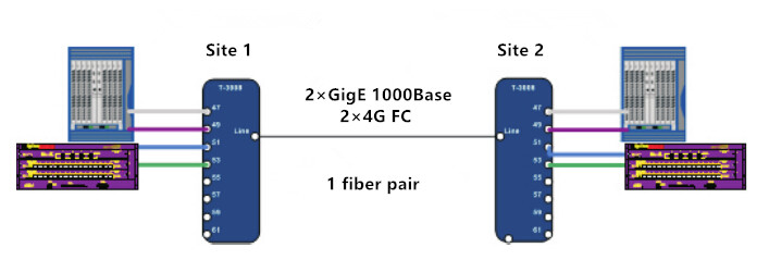
CWDM technology expands fiber capacity by multiplexing optical light signals of different wavelength on a single optical fiber. In a CWDM network, components like CWDM Mux/Demux and CWDM transceivers are indispensable. With CWDM, IP data (Gigabit Ethernet or 10G Ethernet) and storage data (4G/2G/1G Fiber Channel) can be transported over a single fiber infrastructure, eliminating the need for complex protocol conversion.

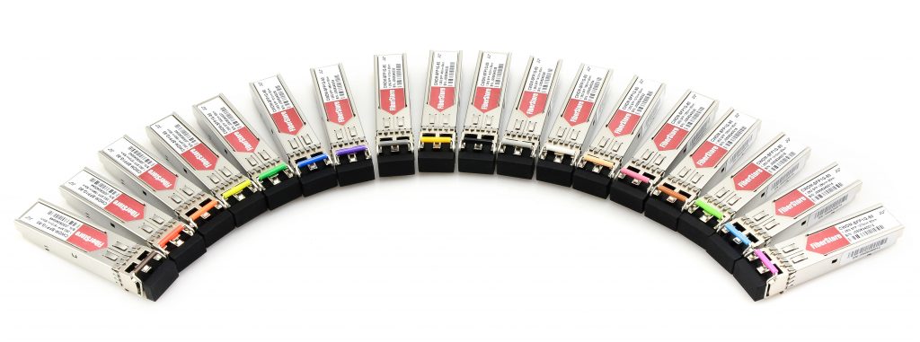
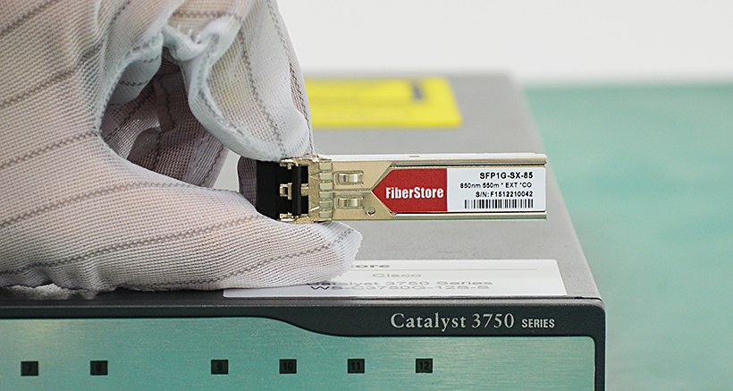
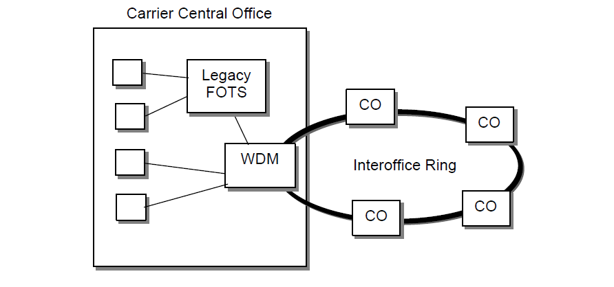
Until now, standalone CWDM solutions are the commonly used methods to transport LAN connections and SAN connections simultaneously between main and recovery sites. Despite that it generates high equipment cost and reduces system reliability. In this case, embedded CWDM emerges as an ideal alternative for use in Fiber Channel applications. Embedded CWDM integrates CWDM optics (like CWDM SFP transceivers) directly into the Fiber Channel switch or Ethernet router, offering better reliability and simplicity. Thus instead of laying more fibers and equipment, users can extend system capacity only by adding new CWDM SFPs, which greatly reduces human labor and overall expenditure.

embedded CWDM solution with CWDM SFPs

Embedded CWDM for Distance Extension in 4G Fiber Channel

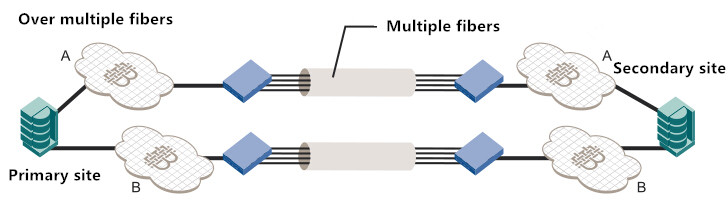
While used for SAN distance extension, CWDM functions to reduce the amount of required WAN fibers. Here we take the example of a SAN extension between a primary site and secondary site. With solution A, the implementation requires several WAN fibers to get the capacity required.

multiple fiber in SAN

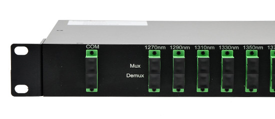
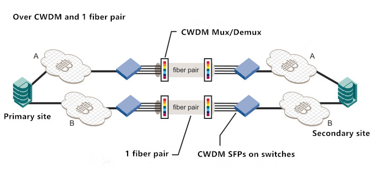
As for solution B, CWDM is adopted to multiplex several signals onto a single fiber pair. CWDM SFPs are directly plugged into the ports from the Fiber Channel switch to generate signals of specific CWDM wavelength. The CWDM Mux combines wavelengths onto a fiber pair, while the CWDM Demux splits these wavelengths into several fiber on the receiver site. Thus the number of required WAN fibers is reduced by the number of wavelengths used.

embedded CWDM in SAN extension

Benefits of Embedded CWDM Solution

Embedded CWDM system is easier to operate, which requires no additional network management or training. It introduces more reliability, flexibility and simplicity due to fewer components involved in the system. And its advantages become more evident when it comes to cost: Embedded CWDM solution simply offers lower investment expenditure and operation cost, since it removes the need for adding new fibers and equipment, which can be cost-prohibitive. Even that CWDM SFPs and CWDM Mux/Demux should be involved in CWDM system, the overall cost is just a fraction of multiple fiber transmission.

Conclusion

CWDM solution allows IT managers to achieve network capacity expansion in a more cost-effective, simplified and flexible way. Besides, it also provides enhanced performance and reliability for current need and future growth. For more CWDM solutions and information, visit www.fs.com or contact us via sales@fs.com.

How to Build 10G CWDM Network

As a passive technology, CWDM allows for any protocol to be transported over fiber optic link at specific wavelengths. CWDM technology is a cost-effective and simple method to increase the capacities of fiber optic network, by using different wavelengths to carry different signals over a single optical fiber. The wide deployment of CWDM network is greatly driven by its affordable cost.

What Is Need for A 10G CWDM Network?

The deployment of a 10G CWDM network is relaying on the exiting fiber optic network. Adding some components on the existing network can largely increase its capacity for data transmission. Here will introduce the key component and an important step during 10G CWDM network deployment.

CWDM Mux/Demux
A Key Component—CWDM Mux/Demux

A key component should be deployed is CWDM Mux/Demux, which combines different wavelength signals from different optical fibers into a single optical fiber, or separates different wavelength signals coming from a single optical fiber to separate optical fibers. The Channel number of a CWDM Mux/Demux is an important factor to divide this device. Standards have identified 18 CWDM Channels. Most of the CWDM Mux/Demux are provided with Channel number range from 2 to 16. However, FS.COM provides a 18-Channel CWDM Mux/Demux which can increase capacity of CWDM network to the most. CWDM Mux/Demuxs also come into a variety of package form factors. The most commonly used are LGX design, rack design and pigtail design.

CWDM Cabling
An Important Step—Connecting CWDM Mux/Demux With 10G Switch

Connecting CWDM Mux/Demux with a 10G switch, is the most important step to build a 10G CWDM network. In simple, to add more devices on the fiber optic network by CWDM technology is to connect the CWDM Mux/Demux with the 10G switches which are linked to the end users. To link CWDM Mux/Demux with the switches, fiber patch cable and 10G CWDM SFP+ transceiver are needed. 10G CWDM SFP+ transceiver should be installed on the switch SFP+ port (some switches use XFP port, then 10G CWDM XFP transceiver is required). Then a length of fiber patch cable should be used to link the transceiver and CWDM Mux/Demux.

CWDM SFP+

How to Select to Right 10G CWDM SFP+ Transceivers?

Choose the Right Working Wavelength: To ensure the right connection, the specific wavelength port should be connected to the same wavelength CWDM SFP+ transceivers. For example, the port on the CWDM Mux/Demux marked with 1270 nm, should be connected to a CWDM SFP+ transceiver that working over wavelength of 1270 nm. As there are 18 different CWDM wavelengths, 10G CWDM SFP+ transceivers that are provided in the market also can 18 different versions for these wavelengths.

Choose the Compatible CWDM SFP+: It is common sense that the fiber optic transceiver should be compatible with the switch which it works on. For instance, if you are using a Cisco switch, the fiber optic transceivers that you used with this switch should be original Cisco transceivers or Cisco compatible transceivers which are provided by third party vendors. The latter is usually the choice of many companies, this is because third party transceivers are usually more cheap than the original brand transceivers. Fiber optic transceivers provided by third party vendor like FS.COM are all fully tested on original brand switch to ensure their compatibility and quality. What’s more, most of FS.COM fiber optic transceivers support same day shipping. Select the right SFP do not only cut your cost and time, but also provide high network performance.

Choose the Transmission Distance According to Your Needs: CWDM network is usually deployed for long distance transmission. Thus the 10G CWDM SFP+ transceiver that are provided in the market usually support transmission distance longer than 20 km, some can support link length up to 80 km or more. You can select the 10G CWDM SFP+ according to your requirements.

Here list the generic whole band 10G CWDM SFP+ fiber optic transceivers that support link length of 20km, 40km and 60km. If you need the brand compatible CWDM SFP+, kindly contact sales@fs.com or visit FS.COM for more details.

Wavelength 20km CWDM SFP+ 40km CWDM SFP+ 60km CWDM SFP+
1270 nm 44170 44363 44743
1290 nm 44171 44364 44744
1310 nm 44172 44365 44745
1330 nm 44173 44366 44746
1350 nm 44269 44367 44747
1370 nm 44270 44368 44748
1390 nm 44271 44369 44749
1410 nm 44272 44370 44750
1430 nm 44273 44371 44751
1450 nm 44274 44372 44752
1470 nm 44299 44550 44827
1490 nm 44300 44551 44828
1510 nm 44301 44552 44829
1530 nm 44302 44553 44830
1550 nm 44303 44554 44831
1570 nm 44304 44555 44832
1590 nm 44305 44556 44833
1610 nm 44306 44557 44834
Conclusion

With the improvement of technology and market, the cost of CWDM network has decrease a lot. To build a 10G CWDM network is affordable to most companies. For full series of CWDM network Solutions, please visit the following link: WDM Solution

Connect Cisco Catalyst 3750 Series Switches to Network

Cisco Catalyst 3750 series switches are widely used in today’s access layer of the network, which can provide Ethernet speed of Gigabit. There are a variety of configurations in this series of Cisco switches. They can fit different applications and offering forward data rates from 32G to 128G by using Cisco StackWise technology. It is an economical solution to many midsize enterprises and office. However, to make full use of these switches, how to connect them to network becomes very important. This post will illustrate Cisco Catalyst 3750 series switches connection in details.

cisco catalyst 3750 and optics

Do You Know Cisco Catalyst Series Switches?

The ports on switches decide what types of connectors and cables can be connected with the switches. Thus, let’s get a close look at Cisco Catalyst 3750 switches ports details first. As mentioned, one of the biggest advantages is that Cisco Catalyst 3750 can support Cisco StackWise technology. Up to nice physical Catalyst 3750 switches can be interconnected into one logical switch with a high performance of 32G or 128G. This is largely depending on the StackWise ports on the rear panel of the switch as shown in the following picture.

Cisco Catalyst 3750G-48TS rear panel

Another great advantage of Cisco Catalyst 3750 switch is its great flexibility and adaptability owning to its various configurations. The Ethernet ports of Cisco Catalyst 3750 can support data rage from 10M to 1G. For instance, or example, Cisco Catalyst 3750G-12S contains 12 SFP ports, Cisco Catalyst 3750G-24TS-1U has 24 Ethernet 10/100/1000 ports plus 4 SFP uplinks in 1 rack unit (RU) height, Cisco Catalyst 3750G-48PS is armed with 48 Ethernet 10/100/1000 ports with IEEE 802.3af PoE and 4 SFP uplinks. The following picture shows the detailed ports information of Cisco Catalyst 3750G-48TS, which has 48 Ethernet 10/100/1000 ports and 4 SFP uplinks.

Cisco Catalyst 3750G-48TS front panel

Connecting Cisco Catalyst 3750 Series Switch to Network

There are mainly two types of ports on Cisco Catalyst 3750 switches: RJ45 and SFP. Different cables and connectors are used to connect the switches to network. The following will offer detailed information about how to connect these ports.

Cisco Catalyst 3750 Switch 10/100/1000 Ports Connection

10/100/1000 Ports on Cisco Catalyst 3750 are RJ45 ports, which should be connected with copper cables (as shown in the following picture). For different applications, the cable types are also different. For example, when connecting Cisco Catalyst 3750 to workstation, servers, router, the straight-through cables are suggested to use with RJ45 connector. When it the switch is connected to repeaters, crossover cable is recommended. When connecting to 1000Base-T-compatible devices, be sure to use a twisted four-pair, Cat5 cable.

Cisco Catalyst 3750 RJ45 connection
Cisco Catalyst 3750 Switch SFP Module Ports Connection

Most Cisco Catalyst 3750 switches have several SFP ports on their front panel. They can support Gigabit Ethernet, by using SFP modules related. Both copper and fiber optic links can be built with these ports and SFP modules. If connected with fiber optic 1000Base-LX or 1000Base-SX SFP modules a link supporting Gigabit Ethernet based on fiber optic can be built. If connected with copper SFP module like 1000Base-T, a copper link will be built. The following picture illustrates the connections with fiber optic SFP module port and Copper SFP module port from left to right separately.

Cisco catalyst 3750 SFP port connection

Cabling Solution for Cisco Catalyst 3750 Series Switches

More related cables and modules that Cisco Catalyst 3750 switches supporting are listed in the following chart for your reference.

Port Type
Data Rate
Connectors/Modules & Cables
RJ45 Ports 10BASE-T ports  RJ-45 connectors, two-pair Cat 3, 4, or 5 unshielded twisted-pair (UTP)
10BASE-T PoE ports  RJ-45 connectors, two-pair Cat 3, 4, or 5 UTP cabling power pins 1, 2 (negative) and 3, 6 (positive)
100BASE-TX ports  RJ-45 connectors, two-pair Cat 5 UTP
100BASE-TX PoE ports  RJ-45 connectors, two-pair Cat 5 UTP, power on pins 1, 2 (negative) and 3, 6 (positive)
SFP Ports 100M GLC-GE-100FX LC duplex, MMF
GLC-FE-100FX
GLC-FE-100LX LC duplex, SMF
GLC-FE-100BX-D LC simplex, SMF
GLC-FE-100BX-U
1G GLC-SX-MM LC duplex, MMF
GLC-SX-MMD
SFP-GE-S
GLC-EX-SMD LC duplex, SMF
GLC-LH-SM
GLC-ZX-SM
SFP-GE-Z
SFP-GE-L
CWDM SFP
DWDM SFP
GLC-BX-U LC simplex, SMF
GLC-BX-D
GLC-T RJ-45, Cat 5

All the above mentioned products are fully tested in FS.COM Test Center. Please contact sales@fs.com for more details.

Fiberstore WDM Solution

WDM Application Overview
Since the advent of optical communications,great technological efforts happen to be dedicated to the exploitation of the large bandwidth of optical fibers.The Wavelength Division Multiplexing (WDM) Techonology is such one of these techonologies.WDM provide high performance multiplexing or de-multiplexing for various of applications. CTC Union WDM product family covers following wavelength windows widely used in optical fiber systems: From 1471nm to 1611nm for CWDM optical communications.The optical multiplexers are utilized to combine signal in the traffic card (single channel transponders or GE Multiplexer) onto a single pair of fiber.The WDM components cash wider operating bandwidth,lower insertion loss,higher power handling,high isolation,etc.(Application diagram see Figure 1.2.3)

ph_healthcare_dwdm_diagram_lg

Figure 1. WDM Application Digram

local network application

Figure 2.Local Network Application—Access

Local Network Application—Interoffice

Figure 3. Local Network Application—Interoffice

Fiberstore WDM VALUE PROPOSITION
1.Significantly increases the amount of data transmitted over a single fiber (up to 80x)
2.Expands the capacity of the network without laying additional fiber
3.Allows Operators of Storage Area Networks (SANs) and Datacenters to increase bandwidth between sites without
4.leasing additional fiber from carriers
5.Flexibility: each wavelength can carry a different type of data(Ethernet, Fibre Channel, SONET/SDH, etc)
6.Easy to manage

Fiberstore’s OPTICAL NETWORK BUILDING BLOCKS
CWDM & DWDM Passive OADM and MUX/DEMUXs
CWDM & DWDM SFP and GBIC Transceivers
DWDM XFP
WDM transponder

Fiberstore Hot sale WDM Product
Fiberstore CWDM MUX DEMUX
CWDM MUX/DEMUX (Coarse Wavelength Division Multiplexer/Demultiplexer) is a flexible and low-cost solution that enables the expansion of existing fiber capacity. Coupled with highly reliable passive optics certified for environmentally hardened applications,the CWDM MUX/DEMUX solution lets operators make full use of available fiber bandwidth in local loop and enterprise architectures.Fiberstore CWDM MUX/DEMUX modules split up to 18 channels (20 nm spaced) to a single fiber.The standard packages are ABS Plastic Box,19″ Rack Mount Chassis and LGX Metal Box.No matter what kind of connectors (such as FC, ST, SC, LC, etc.) are all available,and we can also mix connectors on one device.

4CH CWDM mux single fiber details

Fiberstore DWDM MUX DEMUX
Fiberstore DWDM MUX DEMUX with 50GHz/100GHz/200GHz channel spacing can be used to combine or separate wavelength channels at standard ITU grid.The common configuration including 2,4,8,16,24,32,40,44,and 48 channels.These DWDM modules passively multiplex the optical signal outputs from 4 or more electronic devices,and send them over a single optical fiber and then de-multiplex the signals into separate,distinct signals for input into electronic devices at the other end of the fiber optic link. Our standard package types of DWDM MUX DEMUX are Field Module ABS Plastic Box,19″ Rack Mount Chassis and LGX Metal Cassette Box.We also supply custom package to meet customers’requirements.All the DWDM MUX DEMUX modules provide excellent optical performance and high reliability to ease of fiber handling and power saving solution.

16CH DWDM MUX dual fiber details(1)

Fiberstore CWDM SFP Module
The Fiberstore Coarse Wavelength-Division Multiplexing (CWDM) Small Form-Factor Pluggable (SFP)(Figure 1) provides scalable and easy-to-deploy Gigabit Ethernet(GE) and Fibre Channel(FC) services in optical networks.These products enable the design of flexible multiservice networks.The Fiberstore CWDM SFP provides a convenient and cost-effective solution for Gigabit Ethernet and Fibre Channel in campus,data-center,and metropolitan-area access networks.The Fiberstore CWDM SFP solution consists of ten different pluggable transceivers complimented by different CWDM multiplexer/demultiplexer or optical add/drop multiplexers (OADMs).The CWDM SFP transceivers are compliant with the ITU-T G.694.2 standard CWDM grid.

CWDM-SFP-1470-120-EC

More about Fiberstore’s WDM products and solution,please log in our website: http://www.fs.com

CWDM/DWDM technical overview

CWDM is an optical technology for transmitting up to 16 channels, each in a separate wavelength or color, over the same fiber strand. The CWDM solutions help enable enter-prises and service providers to increase the bandwidth of an existing Gigabit Ethernet optical infrastructure without adding new fiber strands. Unlike DWDM, which can transmit up to 160 channels on the same fiber by tightly packing them, CWDM technology relies on wider spacing between channels. this design makes CWDM a relatively inexpensive technology for transmitting multiple gigabit-per-second signals on a single fiber strand as compared with DWDM because it can support less-sophisticated, and therefore cheaper, transceiver designs. In the point-to-point configuration shown in Figure 1-1, two rndpoints are directly connected through a fiber link. The ITU has standardized a 20-nm channel-spacing grid for use with CWDM, using the wavelengths between 1310 nm and 1610 nm. Most CWDM systems support eight channels in the 1470-to 1610-nm range. The Fiberstore CWDM Gigabit Interface Converter small form-factor pluggable(SFP) solution allows organizations to add or drop as many as eight channels (Gigabit Ethernet or Fibre Channel) into a pair of single-mode (SM) fiber strands. As a result, the need for additional fiber is minimized. You can create redundant point-to-point links by adding or dropping redundant channels into a second pair of SM fiber strands.

9     Figure 1-1


CWDM Technical Overview

CWDM Multiplexer is achieved thruogh special passive (nonpowered) glass devices known as filters. The filters act as prisms, directing lights from many incoming and outgoing fibers (client ports) to a common transmit and receive trunk pots. Optical multiplexing in a ring with CWDM networks is supported with optical add/drop multiplexers (OADM). OADMs can drop off one or more CWDM wavelengths at a specific location and replace that signal with one or more diferent outbound signals. The Fiberstore CWDM GBIC/SFP solution has two main components: a set of eight different pluggable transceivers (Fiberstore CWDM GBICs and CWDM SFP), and a set of different Fiberstore CWDM passive multiplexers/demultiplexers or OADMs. Both the transceivers and the passive multiplexers are compliant with the CWDM grid defined in the standards. CWDM can be used by enterprises on leased dark fiber to increase capacity (for example, from 1 Gbps to 8 Gbps or 16 Gbps) over metro-area distances. One problem with CWDM is that the wavelengths are not compatible with erbium-doped fiber amplifier (EDFA) technology, which amplifies all light signals within their frequency range. CWDM supports up to a 30 -dB power budget on an SM fiber. This restricts the distances over which CWDM may be used. CWDM supports distances of approximately 60 miles (100km) in a point-to-point topology and about 25 miles (40 km) in a ring topology. in some areas, service providers use CWDM to provide lambda or wavelength services. A lambda service is where a provider manages equipment and multiplexes customer traffic onto one or more wavelengths for a high-speed connection, typically bet ween two or more points.

DWDM Technical Overview

DWDM is a core technology in an optical transport network. The concepts of DWDM are similar to those for CWDM. However, DWDM spaces the wavelengths more tightly, yielding up to 160 channels. The tighter channel spacing in DWDM requires more sophisticated, precise,and therefore more expensive transceiver designs. In a service provider is backbone network, the majority of embedded fiber is standard SM fiber with high dispersion in the 1550-nm wubdiw, DWDM supports 32 or more channels in the narrow band around 1550 nm at 100-GHz spacing, or about 0.8 nm, as illustrated in Figure1-2. Because of the EDFA compatibility of the wavelenths used, DWDM is also available over much longer distances than CWDM and supports metropolitan-area network (MAN) and WAN applications. In practice, signals can travel for up to 75 miles (120 km) between amplifiers if fiber with EDFA is used. At distances of 375 miles (600 km) to 600 miles (1000 km), the signal must be regenerated.
8

Figure 1-2

DWDM can be used as a high-speed enterprise WAN connectivity service. Typical DWDM uses include connectivity between sites and data centers for example 1-, 2-, or 4- Gbps Fiber channel; IBMfiber connectivity (FICON) and Enterprise System Connection(ESCON); and Gigabit and 10 Gigabit Ethernet. Protection options include client-side safeguards using rerouting, an optical splitter that allows the signal to go both ways around a ring or line-card-based protection that detects boss of signal and wraps.

Continue reading