Tag Archives: FTTH

PLC Splitter Selection Guide

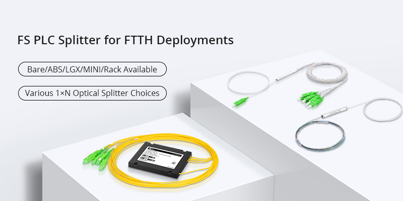
PLC splitter is a simple passive component which plays an important role in the applications of technologies like GPON, EPON and BPON. It allows a strand of fiber optic signal being equivalently splitted into several strands of optical signal, which can support a single network interface to be shared by many subscribers. When selecting it, split ratios should always be considered. However, with the network cabling environment becoming increasingly complex, various PLC splitters with different package form factors are being invented. Now the package form factor of it is also a key factor to be considered. This post will introduce the most commonly used PLC splitters in different package form factors for your reference during selection.

Bare Fiber PLC Splitter

Bare fiber PLC splitter is commonly used in FTTx projects. It leaves bare fiber on all its ends. Thus, they can be spliced by network engineer freely according to the applications. Meanwhile, it requires the least space during cabling. They can be installed in fiber optic splicing closure easily to provide FTTH signal distribution.
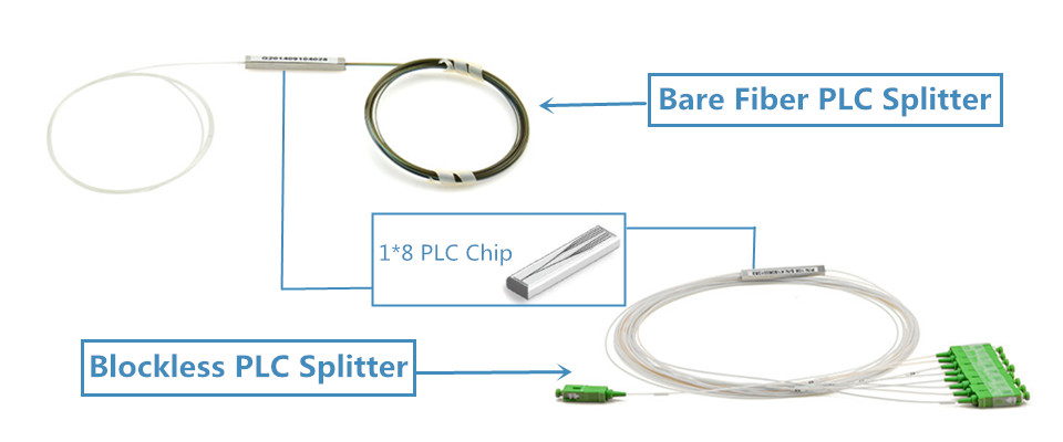
blockless bare fiber PLC splitter

Blockless PLC Splitter

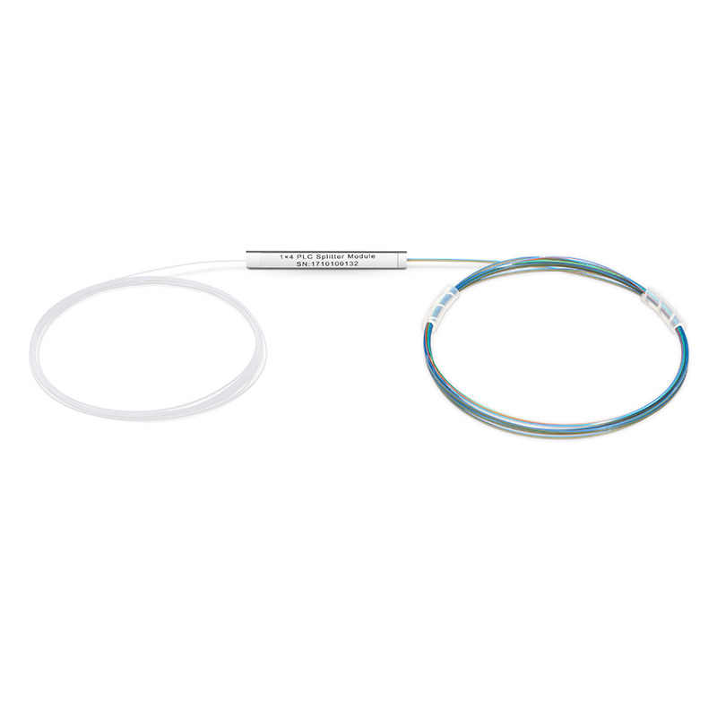
A blockless PLC splitter looks like a bare fiber splitter. The main differences are that the blockless one is usually terminated with fiber optic connectors and it uses a compact stainless tube package. It is also common that many bare fiber PLC splitters also use stainless tube package for the split chip.

Fanout PLC Splitter

Fanout PLC splitter generally uses 0.9mm buffer fiber, added with a length of ribbon fiber terminated with fanout kit behind the PLC split chip. The splitter ratios of it also come in various types. The following picture shows a 1:8 fanout version which is terminated with SC/APC connectors.
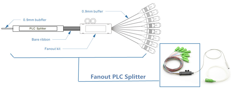
fanout PLC splitter

ABS PLC Splitter

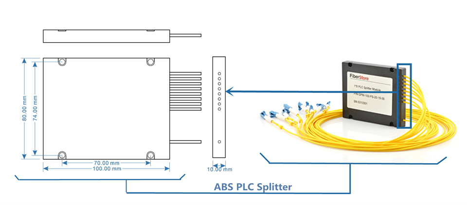
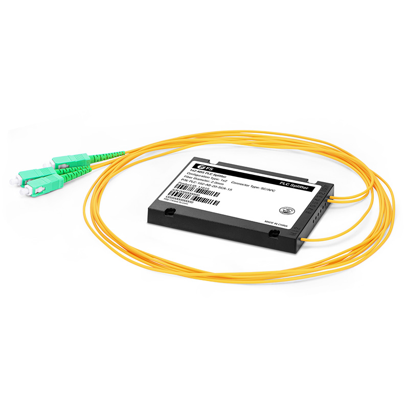
ABS PLC splitter uses ABS plastic box to holding the splitter chip. The inbound fibers and distribution fibers are arranged on the same plate of this ABS box, which can provide easier and more flexible cabling. Except providing reliable protection, it can also be installed in a variety of boxes or enclosures. It is very commonly to install a it in a standard 19-inch rack unit.

ABS PLC splitter

LGX Box PLC Splitter

LGX Box PLC splitter looks like an MTP LGX cassette. It houses the whole splitter inside a metal box and leave fiber optic adapters for both inbound fibers and distribution fibers on its front panel. The LGX splitter can be used stand alone or be installed in the standard rack unit or fiber enclosures for better cabling.
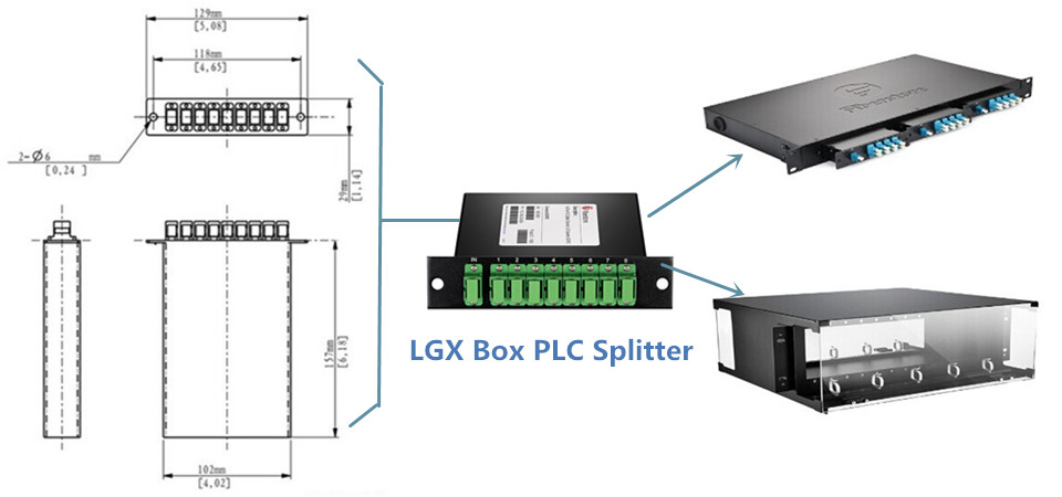
LGX PLC splitter

Mini Plug-in PLC Splitter

Mini plug-in PLC splitter is now widely used in FTTx project, especially at the distribution points near the end users of the FTTx networks. It provides fast installation and low space requirement helping to alert the deployment of FTTs projects. Fiber pigtails for input and output can be directly connected with this passive component easily.
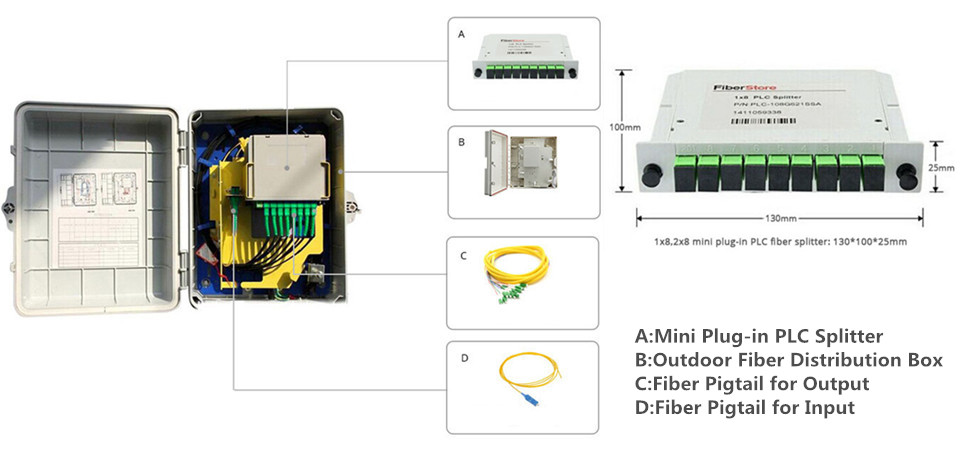
mini plug-in PLC splitter

Tray Type PLC Splitter

Tray type PLC splitter also uses a space saving package form factor for better cable management. However, it uses a international 19-inch design which can be deployed in ODF for compact cable management and signal distribution. With this design, the ports on tray type splitter are clearly marked, which can reduce the faults caused by wrong connections.
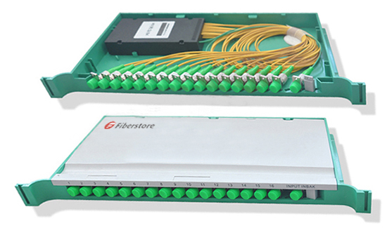
tray type PLC splitter

Rack Mount PLC splitter

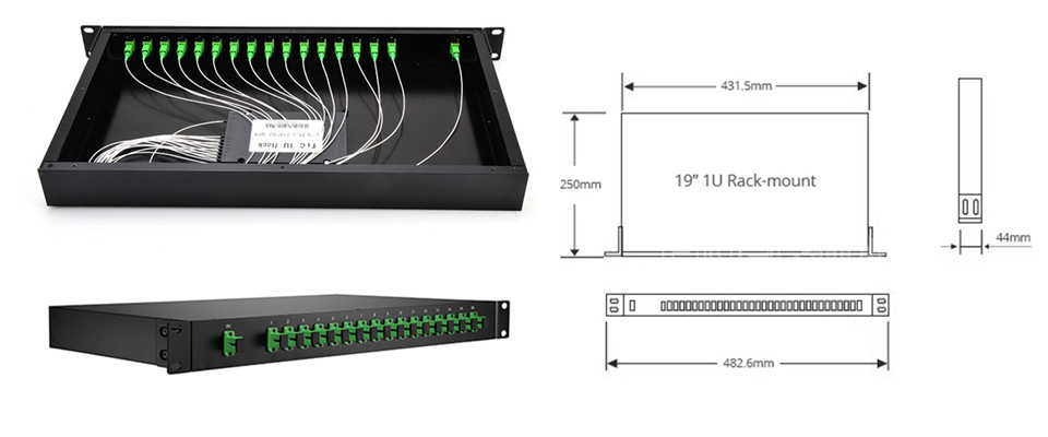
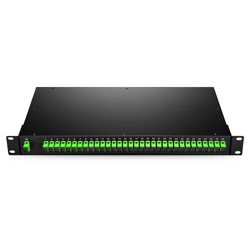
Rack mount PLC splitter is designed to meet the requirement of high cabling density for data centers or server room. It can be firmly installed on the data center or server racks. It is an ideal solution for high density cabling environment. FS.COM can provide PLC splitter ports up to 64 in 1U 19-inch rack. The following picture shows the details of a 1:8 rack mount one provided in FS.COM.

rack mount PLC splitter

FS.COM PLC Splitter Solution

PLC splitter is a cost-effective passive optical component enabling a single network interface to be shared by two or more users. Selecting the right package form factor for it can help a lot during both the network deployment and maintaining. Most of the above mentioned splitters in different package form factors are all being provided in FS.COM. Customized ones are also available in FS.com. Kindly contact sales@fs.com for more details if you are interested.

Source:

How Many Fiber Optic Splitter Types Are There? – FS Community


Causes of Mechanical Splice Termination Failures

FTTH (fiber to the home) has become increasingly popular in optical communication industry. Fiber optic termination, as one of the topics which have never been out of fashion in this field, has naturally become a focus of FTTH network deployment, especially the indoor termination. In FTTH network, mechanical splice connectors are usually used in FTTH indoor termination with the advantages of flexibility, fast-installation and cost-effective. Currently manufactures can provide various types of mechanical splice connectors of high quality which have low insertion loss and high performance. However, no matter how excellent the mechanical splicing technology is, there are still fiber optic termination failures and bad fiber optic termination due to improper operation. To avoid it, this post is to offer the causes of mechanical splice termination failures.

The Basic of Mechanical splicing

Before finding the cause of mechanical splice failure, the basic of mechanical splicing should be introduced. To finish a mechanical splice, the buffer coatings of fiber optic should be removed mechanically with sharp blades or calibrated stripping tools. In any type of mechanical stripping, the key is to avoid nicking the fiber. Then the fibers will be cleaved. Two fiber ends are then held closely in retaining and aligning a mechanical splice connector with some index matching gel between them. The gel are used to form a continuous optical path between fibers and reduce reflecting losses.

mechanical splicing

Causes of Mechanical Splice Termination Failures

Mechanical splice connector is sensitive to many factors. There are also a large number of factors to cause failures. However, most of the factors are located at the end face of fiber optic. The following is to describe them in details.

Contamination

When facing mechanical splice failures, there would be no argument that contamination is the first thing to think about. There are many ways that contamination can be carried into the fiber termination splices. Generally, there are the following possible causes of splice contamination:

  • Using a dirty cleave tool: as the fiber should be cleave before inserted in the connector, a fiber optic cleaves would be used. If a dirty cleave is used, the contamination would be attached on the end face of the fiber optic and be embedded in the connector. Thus, do remember to clean the surfaces thoroughly with alcohol wipes;
  • Wiping the fiber after cleaving;
  • Setting the connector or fiber down on a dusty surface;
  • Heavy airborne dust environment;
  • Glass fragments from insertion broken fibers, or applying excessive force;
  • Polluted index matching gel.

comtamination

Please note that once the contamination is carried inside the mechanical splice connector, especially with the index matching gel, there would be little possibility to clean them out, which means the connector may be scrapped.

Glass Fragmentation

Improper operation like overexertion when inserting the fiber optic into the mechanical splice connector might break the fiber optic and produce glass fragmentation which will cause air gap and optical failure. Or if a broken fiber if inserted, there will also be optical failure. If the glass fragments are embedded in the connector, they cannot be cleaned out and the connector would be scrapped. Thus, be gentle and carefully when splicing the fiber ends.

glass-fragmentation

Bad Cleave

Cleaving the fiber optic is an important step during fiber optic mechanical splicing. The quality of the cleave can decide the quality of the optical splice transmission to some degree. It is not easy to inspect the cleave quality in the field. There are several possibilities there might cause the bad cleaves:

  • Dull or chipped cleave tool blade
  • The bent tongue on the cleave tool concentrated too much bend stress on the fiber
  • Bending the fiber too much or too tight of a radius
  • Applying no tension or insufficient tension to the fiber while cleaving.

bad cleave

Excessive Fiber Gap

Fiber gap is another factor that might cause the fiber optic termination failure. The fiber optic transmission is very sensitive to the gap between two fiber ends in the mechanical splice connector. Improper operations that might cause the excessive fiber gap are listed as following:

  • Cleaving the fiber without enough lengths;
  • The fiber is not fully inserted, or pulled back during termination;
  • The fiber was not held steady during termination and was pushed back into the fan-out tubing when terminating outdoor cable.

These faults can be corrected one time.

fiber gap

Excessive Cleave Angle

During fiber cleaving, cleave angle can be produced easily and is difficult to be inspected in field. These angles are typically ranging from 1 to 3 degree. Even with precision tool, there might still be cleave angle ranging from 0.5 to 1 degree. The angle is generally produced by bent tongue, fiber bending or insufficient fiber tension.

cleave-angle

However the cleave angles can be corrected by fine tuning with a VFL (visual fault locator). Rotating the fiber while using a VFL and terminate the connector at the position (as shown in the following picture).

VFL-tuning-fiber

Conclusion

Fiber optic mechanical splicing gives quick and high quality result at a low price for fiber optic termination. Choosing the right fiber optic mechanical splice connector and fiber optic cleaver of high quality is not enough. Acknowledge the possible causes to fiber optic termination failures and use the right tools with skills can reduce the risk of termination failure effectively.

Source: https://www.fs.com/blog/causes-of-mechanical-splice-termination-failures.html

Lower FTTH Cost and Increase Reliability With Tight Buffer Indoor/Outdoor Cable

FTTH (Fiber to the Home) network connects a large number of end users to a central point known as an access node to provide the application and services of high speed. The links between end users and access node are achieved largely by fiber optic cables. Loose buffer cables and tight buffer cables are commonly used to transmit signals with high speed, which are capable of surviving outdoor environment or indoor environment. However, to accomplish the whole transmission link, loose buffer cables for outdoor application should be connected with the tight buffer cables for indoor application. The splicing and termination of these fiber optic cables come as one of the largest link items in a FTTH system installation budget.

Is There A Better FTTH Cable Solution?

Is there a cost-effective and time-saving solution by using a single type of cable that can survive both indoor and outdoor environment in FTTH network? The answer is YES. Tight buffer indoor/outdoor cable is such a cable. It is a specially designed tight buffer cable which can answer the market call for a single type cable surviving both indoor and outdoor environment. To understand why it is a better choice for FTTH installation, the construction and comparison of loose tube cable and tight buffer cable will be introduced firstly.

Loose Buffer VS Tight Buffer

The “buffer” previously mentioned in “loose buffered” and “tight buffer” is actually a basic component of fiber optic cable and the first layer used to define the type of cable construction. A typical fiber optic cable consists of the optical fiber, buffer, strength members and an outer protective jacket (as showed in the following picture). The buffer literally is used to provide protection and some tensile strength, which are useful when pulling the cable to install it or when it must hang between two suspension points.

cable structure

Loose buffer cable consists of a buffer layer that has an inner diameter much larger than the diameter of the fiber (showed in the following picture). Thus, the cable will be subject to temperature extremes that cause expansion or contraction. That’s why loose buffered cable are usually used outdoor. The loose buffer cables designed for FTTH outdoor application are usually loose-tube gel-filled cables (LTGF cable). This type of cable is filled with a gel that displaces or blocks water and prevents it from penetrating or getting into the cable.

loose buffer cable

Tight buffer cable using a buffer attached to the fiber coating is generally smaller in diameter than loose buffer cable (showed in the following picture). The minimum bend radius of a tight buffer cable is typically smaller than a comparable loose buffer cable. Thus tight buffer cable is usually used in indoor application.

tight buffer

Tight buffered indoor/outdoor cable with properly designed and manufactured can meet both indoor and outdoor application requirements. It?combines the design requirements of traditional indoor cable and adds moisture protection and sunlight-resistant function to meet the standards for outdoor use. Tight buffered indoor/outdoor cable?also meets one or more of the code requirements for flame-spread resistance and smoke generation.

A Better Choice for FTTH Cable Solution

The structure and performance advantages of tight buffer indoor/outdoor cable have been introduced above. How about the other advantages? The following will explain why tight buffered indoor/outdoor cable is a better FTTH cable solution from the aspects of cost and reliability.

Cost

Using the traditional choice of LTGF cables as the outdoor cable, there would be a conversion from one fiber type from another type, which includes prep work on the fiber, the need for splice tray, the routing of fibers in the tray, and other similar detail. Before termination and splicing, the gel of LTGF cable must be cleaned and the breakout point of the main cable must be blocked by some method to prevent oozing of the cable gel. In addition, this cable type must normally be terminated or spliced close to the cable entryway of a building to switch to indoor cable, as it generally incompatible with indoor fiber codes. This time consuming and labor intensive process adds hidden costs to install the LTGF cables.

However, using only tight buffer indoor/outdoor cable for FTTH is much more convenient and cost-effective. A tight-buffered indoor/outdoor cable can be used throughout the link, requiring no transitions at the building entryway. Tight buffer indoor/outdoor cable requires less care to avoid damaging fibers when stripping back the cable. The termination and splicing of these cables are easier than that of LTGF cables.

Reliability

An important reason why choose tight-buffered indoor/outdoor cable for FTTH cable installation is the reliability of the overall system. Splicing are the weakest point in a FTTH network. With splicing, the bare fiber ends are open to dust, dirt, water, vapor, and handing which might reduce the fiber strength and increase brittleness. Choosing loose tube outdoor cable for FTTH, there will be splices after the conversion from one cable type to another type. The splices inside a building may be held in a cabinet that is open to the air, which might decrease the reliability of the FTTH network. Using the tight buffer indoor/outdoor cable could eliminate splicing and improve the installation reliability greatly.

Conclusion

In conclusion, the benefits of tight buffer indoor/outdoor cable are clear. The installer can run a single cable type and remove a transition point between the outside plant and the inside plant, which decrease FTTH installation cost and time effectively. At the same time, the reliability of the overall FTTH network can be increased greatly.

Source: https://www.fs.com/blog/lower-ftth-cost-and-increase-reliability-with-tight-buffer-indooroutdoor-cable.html

Drop Cable and Its Termination in FTTH

FTTH (fiber to the home) networks are installed in many areas covering indoor section, outdoor section, as well as the transition in between. To fulfill the cabling requirements from different areas, different types of fiber optic cable are well developed. Drop cable as an important part of FTTH network forms the final external link between the subscriber and the feeder cable. This blog post will focus on this special outdoor fiber optic cable.

The Basic of FTTH Drop Cable

Drop cables, as previously mentioned, are located on the subscriber end to connect the terminal of a distribution cable to a subscriber’s premises. They are typicality small diameter, low fiber count cables with limited unsupported span lengths, which can be installed aerially, underground or buried. As it is used in outdoor, drop cable shall have a minimum pull strength of 1335 Newtons according to the industry standard. Drop cables are available in many different types. The following part introduces three most commonly used drop cables divided according to the cable structure.

Flat Type Drop Cable, also known as flat drop cable, with a flat out-looking, usually consists of a polyethylene jacket, several fibers and two dielectric strength members to give high crush resistance. Drop cable usually contains one or two fibers, however, drop cable with fiber counts up to 12 or more is also available now. The following picture shows the cross section of a flat drop cable with 2 fibers.

flat drop cable

Figure-8 Aerial Drop Cable is self-supporting cable, with the cable fixed to a steel wire, designed for easy and economical aerial installation for outdoor applications. This type of drop cable is fixed to a steel wire as showed in the following picture. Typical fiber counts of figure-8 Drop Cable are 2 to 48. Tensile load is typically 6000 Newtons.

Figure-8 Aerial Drop Cable

Round Drop Cable usually contains a single bend-insensitive fiber buffered and surrounded by dielectric strength members and an outer jacket, which can provide durability and reliability in the drop segment of the network. The following shows the cross section of a round drop cable with one tight buffered optical fiber.

round drop cable

Drop Cable Connectivity Method: Splice or Connector?

It’s necessary to choose a right architecture for FTTH network from overall. However, drop cable as the final connection from the fiber optic network to customer premises also plays an important role. Thus, finding a flexible, efficient and economical drop cable connectivity method becomes a crucial part of broadband service. Whether to use a fiber optic connector, which can be easily mated and un-mated by hand or a splice, which is a permanent joint? The following will offer the answer and the solutions for your applications.

It is known that splice, which eliminates the possibility of the connection point becoming damaged or dirty with a permanent joint, has better optical performance than fiber optic connector. However, splice lack of operational flexibility compared with fiber optic connector. Fiber optic connector can provide an access point for networking testing which cannot be provided by splicing. Both methods have their own pros and cons.

Generally, splice is recommended for drop cables in the places where no future fiber rearrangement is necessary, like a greenfield, new construction application where the service provider can easily install all of the drop cables. Fiber optic connector is appropriate for applications which flexibility is required, like ONTs which have a connector interface.

Choosing the Right Splice Method

For splice, there are two methods, one is fusion splicing, the other is mechanical splicing. Fusion splicers have been proved to provide a high quality splice with low insertion loss and reflection. However, the initial capital expenditures, maintenance costs and slow installation speed of fusion splicing hinder its status as the preferred solution in many cases. Mechanical splicing are widely used in FTTH drop cable installation in countries, as a mechanical splice can be finished in the field by hand using simple hand tools and cheap mechanical splicer (showed in the following picture) within 2 minutes. It’s a commonly used method in many places, like China, Japan and Korea. However, in US mechanical splicing is not popular.

FTTH Drop Cable Mechanical Splicer

Choosing the Right Connector

For fiber optic connector, there are two types connector for drop cable connection. Field terminated connector, which contains fuse-on connector and mechanical connector, and pre-terminated drop cable, which is factory terminated with connector on the end of drop cable.

Fuse-on connector uses the same technology as fusion splicing to provide the high optical connection performance. However, it requires expensive equipment and highly trained technician, and more time like fusion splicing. Mechanical connector could be a replacement of fuse-on connector (showed in the following picture), if the conditions do not fit the mentioned ones. It could be a time-save and cost-save solution for drop cable termination.

fuse-on connector

If you have no limits in cost and want high performance termination in a time-save way, pre-terminated drop cable could be your choice. Many factories can provide you customized drop cables in various fiber types, fiber optic connector and lengths.

Conclusion

Customer demand for higher bandwidth will continue to drive the development of FTTH as well as its key component like drop cable. Choosing the right drop cable and drop cable termination method is as important as choosing the right network architecture in FTTH.

Source: https://www.fs.com/blog/drop-cable-and-its-termination-in-ftth.html

G.fast Offers Fiber Speed Ethernet Over Copper

The demand for higher data rates is continuously increasing driven by the applications like Cloud Computing, Big Data and Internet of Things. Meanwhile, the strong market competition makes the network operators to improve the network architecture and deliver high speed services. Pure fiber network should be the best solution. There is no wonder that the fiber network is the trend of the future and it is gradually extended closer to users during the transition from copper-based access networks to pure fiber networks. However, it is not favorable to connect the fiber directly to the customer premises and the cost is high in some cases, like old buildings. To find the fast and cost-effective way to deliver Gigabit speed Ethernet, copper access technology is being applied in some cases. This technology is known as G.fast.

G.fast and FTTdp

G.fast, based on the latest VDSL technology including cross talk cancellation and re-transmission, is designed for use in a ‘last-mile’ of less than 250 meters. Combining the advantages of fiber optic access technology and copper access technology, G.fast can deliver data at fiber speed to the customers using telephone copper wires.

The problem with G.Fast is that its ultra-fast speeds only work over very short distances. To shorten the copper distance, FTTdp is usually applied with G.fast. “dp” here stands for “distribution point”. This solution brings the fiber optic cable out of street cabinets and moves it closer to home via the distribution point. The following network diagram shows the difference of FTTH and FTTdp using G.fast. The blue lines represent fiber optic cable, the red ones represent copper wire.

G.fast and HTTdp

G.fast Shifts the Limits of Copper

It seems that there is no need for copper access in building a FTTx connection. But in practice, connecting the fiber directly to the customer premises causes some disadvantages which can be solved by G.fast.

There might be many difficulties when deploying fibers to the user homes, especially some existing buildings. Sometime it is even not possible to deploy fibers to the user homes. In addition, most in-house telephone installations still rely on copper cables for most existing and newly constructed buildings because fibers are expensive and difficult to handle. There is no need to deploy fiber optic cable in building and home when delivering Gigabit Ethernet with G.fast.

The fiber optic based customers premises equipment (CPE) are usually installed by technician. Compared with fiber optic connections, copper-based CPE installation is simple. Just connecting the CPE to the telephone plug with the delivered cable would finish the installation, which can be installed by customer. Thus, G.fast can save the cost for new users and makes the home installation much easier.

Optical fibers can be broken or have transmission loses when wrapped around curves and optical fibers require more protection around the cable compared to copper. What’s more, the fault location from the CPE is not easy. It would cost more to maintain the fiber connections compared with copper connections achieved by G.fast.

G.fast Paves the Way to FTTH

At first glance, G.fast is limiting the transmission from copper to fiber. Actually, G.fast accelerates the deployment of fiber optic networks. It cost a lot of time and money to process the paperwork and get permission of the subscriber before deploying the fiber optic cable. The processing is complicated. Hardware foundation is the main advantages of G.fast which eliminates the need to rewire the whole building and still allows a noteworthy uplift in access speeds. Copper is everywhere in telecommunication network. The hybrid copper/fiber approach—G.fast making full use of the telephone wires in the buildings actually makes the customers closer to optical fibers in time save and cost save manners. In this way, the transmission from copper to fiber is actually being promoted by G.fast.

Weighing time, broadband speed and cost, operators figure out that applying G.fast in FTTH is an economical and time-saving way to bring Gigabit speed Ethernet to the users. To capture market share of broadband service, some network operators are considering to use G.fast. Alcatel-Lucent and communications services company BT have already started a consumer trial of G.fast technology in Gosforth (situated in North-Eastern England), for offering ultra-broadband access to consumers.

Source: https://www.fs.com/blog/delivering-gigabit-ethernet-with-g-fast.html