Tag Archives: Fiber patch cable

LC-LC Patch Cable in Data Center

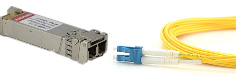
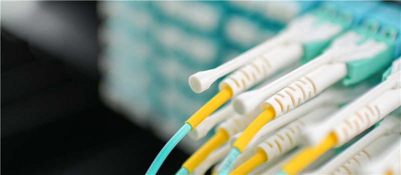
LC-LC patch cable has already become the main force of high density cabling network infrastructure. To future increase the profits of LC-LC fiber patch cable, manufactures has invented LC-LC patch cables of different features to meet various requirements in data center and increase the network performance.

What Kind of Fiber Patch Cable Is Required in Data Center?

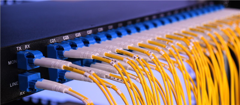
Data center is a place of thousands fiber links. The selection of fiber patch cables will directly affect the network performance. More and more data centers choose to select fiber patch cable of high performance. Generally, insertion loss and return loss of connectors terminated on patch cable and light loss of optical fiber used for fiber patch cable are three most basic factors for fiber patch cable selection. To satisfy the increasing demands for higher density and easier management in data center, the optimization of fiber patch cable has never stopped. The following introduces several popular LC-LC fiber patch cables which represent the trends of fiber patch cable that data center is asking for.

LC-LC fiber patch cable

Low Insertion Loss and Bend Loss LC-LC Patch Cable

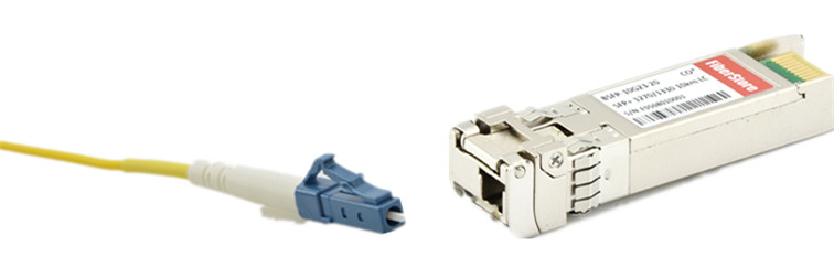
When a length of fiber patch cable is connected in network, optical light loss occurs at the optical fiber and the connectors terminated on it. There are different optical light losses, among which insertion loss at the connectors and bend loss in fiber optic cables are the two most commonly light losses that technicians are trying to overcome. Manufactures provides LC-LC fiber patch cables which can minimize these losses to the most.

Insertion loss refers to the fiber optic light loss caused when a fiber optic component insert into another one to form the fiber optic link. To provide low insertion loss patch cable, LC connectors terminated on the patch cable has been optimized. Standard LC-LC patch cable usually has an insertion loss less than 0.3 dB. However, for upgraded LC-LC patch cable, the insertion loss is usually lower than 0.2 dB. To decrease the bend loss, a type of bend insensitive fiber (BIF) has been used in fiber patch cable. With optimized LC connectors and bend insensitive fiber, LC-LC fiber patch cable could provide lower light loss during network transmission.

uniboot LC cable

High Density LC-LC Patch Cable

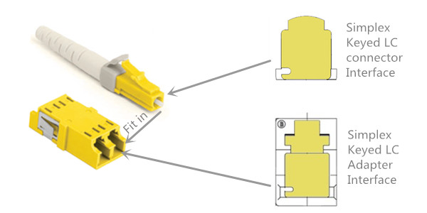
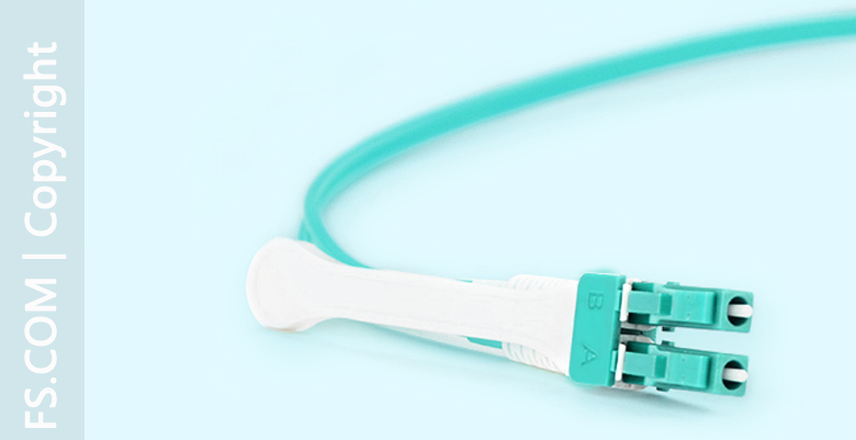
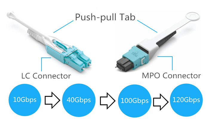
LC connector was invented for higher cabling density. standard duplex LC-LC fiber patch cable can provide much higher cabling density than other duplex fiber patch cables. To further increase cabling density in data center, the connectors and cable diameter of LC-LC patch cable are becoming smaller. Uniboot LC-LC patch cable is a typical example. This kind of fiber patch cable designed the two fibers of the duplex patch cable into a single cable. In adding the two connectors terminated at each end of the duplex patch cable share the same boot. With less using cable counts, uniboot patch cable can provide higher cabling density and better cooling environment in data center.

Polarity Switchable LC-LC Patch Cable

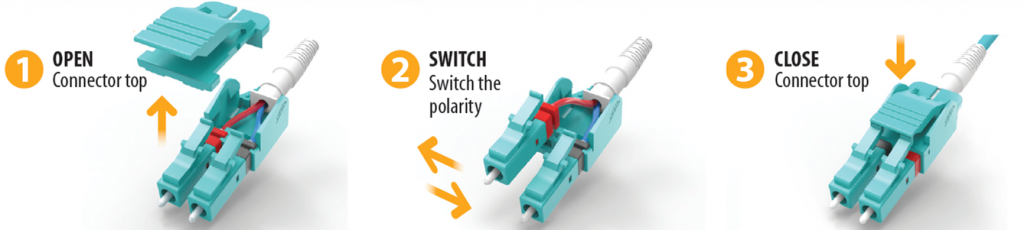
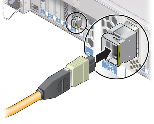
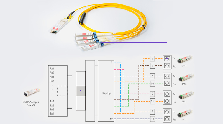
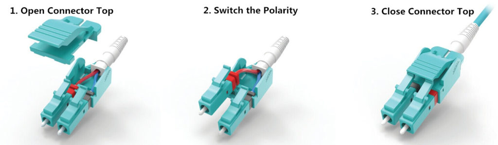
The development of patch cable won’t stop at low loss and high density. Making fiber patch cable easier-to-use is also important. Polarity of fiber patch cable matters a lot during installation of fiber patch cable, especially for duplex fiber patch cable and MTP patch cable. It is common to change the polarity of a duplex patch cable during deployment. Technicians might need tools to change the polarity of patch cable. However, a polarity switchable LC-LC patch cable can make things much easier. Without any tools you can polarity reversal could be really easy. The following picture shows the polarity reversal of a special designed LC-LC patch cable.

polarity switchable LC patch cable

Conclusion

LC-LC patch cable has been designed into many different types. A high performance fiber patch cable should not only provide low insertion loss and bend loss, but also higher cabling density and easy-to-use features. This is also the trend of data center development.

How Many Choices Do You Still Have for Fiber Patch Cable?

Fiber patch cable, also known as fiber jumper, is a key component in today’s fiber optic network. They play the role of veins in the whole fiber optic network bringing fiber optic signals between devices.

How to Select Standard Fiber Patch Cable?

During the selection of standard fiber patch cables, several questions are usually take into consideration:

  • What’s the fiber type of the patch cable? The available selection are Multimode (OM1, OM2, OM3, OM4) and single-mode (OS1 and OS2).
  • What’s the connector type and connector polishing type on the two ends of fiber patch cable? Currently the most commonly used fiber patch cables are usually terminated with LC, SC and MPO connectors.
  • What’s the fiber count of the patch cable? Simplex (one fiber) and duplex (2 fibers) fiber patch cable are very common. For fiber patch cables terminated with MTP/MPO connector or breakout fiber patch cables. Their fiber count would be larger, sometime up to 24 fibers or more.
  • What’s the material of the fiber patch cable jacket? PVC, LSZH, Armored, and OFNP are the choice of most situations.
Not All Fiber Patch Cable Are Created Equal

Now with the fiber optic cable being widely used in a variety of industries and places, the requests for fiber patch are being refined. Fiber patch cable are being required to be improved and provide more possibilities to satisfy various application environments. Actually, many specially fiber patch cable have been created to answer the market call. Here will introduce several unique but useful fiber patch cable for your references.

Bend Insensitive Fiber Patch Cable for Lower Signal Loss

Bend loss issues are always a headache problem for most fiber optic network designers and installers. Why? Cause signal loss caused by bend loss issues are really hard to handle. In addition the bend loss issues are difficult to locate. That’s why bend insensitive fiber patch cables are created. Literally, it tells us that this type of fiber patch cable is not as sensitive as other fiber patch cables. The secrets is lays on the fibers which is made of bend insensitive glass. More and more data centers and FTTH systems are tend to use these bend insensitive fiber patch cables, because they do not provide lower signal loss, but also provide a much more durable and easy to maintain networking environment. Fiber optic installer is able to save installation cost with faster installation due to easier fiber optic cable handling.

bend insensitive fiber patch cable
Keyed LC Fiber Patch Cable for Data Security

Keyed LC fiber patch cable, is also called secured LC fiber patch cable. This is because, the fiber optic connectors on the two end of the patch cable are specially designed LC connectors, which can ensure the data security at the mechanic level. Keyed LC fiber patch cable is identifies by the connector color. Keyed LC fiber patch cable is just a part of the Keyed LC connectivity product family. It should be used with the same colored fiber adapters or fiber adapter panels. Each color of a set of keyed LC connectivity products represents a unique keying pattern that only allows matched color mating. This is how keyed LC fiber patch cable can provide data security for fiber optic network. A previous article (Secure Fiber Optic Link With Keyed LC Connectivity Products) of my has introduce keyed LC connectivity in details, kindly follow the link on the article title if you need more information about them.

keyed-lc-connector-and-adapter
Uniboot LC Fiber Patch Cable for Easier Cable Management

Uniboot LC fiber patch cable is a fiber patch cable with two fibers wrapped in the same strand of cable. A duplex LC fiber optic connector which can provide easy polarity reversal is terminated on each end of the uniboot LC fiber patch cable. The following picture show the polarity reversal of a typical uniboot LC fiber patch cable. With less cabling space are require, better cooling is available. With easier polarity reversal, no additional tools are required. And easier cable management can be enjoyed.

uniboot LC fiber patch cable
HD TAB Fiber Patch Cable for Space Saving

HD (high density) TAB fiber patch cable is a fiber patch cable with its connectors attached with a push pull tab, which can provide easier finger access and cable locating. Today’s fiber optic network is increasing depended on high density which results in difficult finger access and difficult cable management. With a push-pull tab attached on the connector, problem are solved easily. The connecting and disconnection of fiber patch cables will be easier without affecting other surrounding links. Currently most HD TAB fiber patch cables available the market are terminated with LC and MTP/MPO connectors. For more information about this type of patch cable kindly visit my article: Cabling With High Density Push-Pull Tab Patch Cords.

HD TAB fiber patch cable
HD Uniboot LC Fiber Patch Cable—Space Saving to the Extreme

HD uniboot LC fiber patch cable combine the advantages of uniboot LC fiber patch cable and HD TAB fiber patch cable. Combining two optical fibers in a single cable strand and attaching a push-pull tab on the connectors, HD uniboot LC fiber patch cable can minimize the required cabling spaces to extreme. It is an ideal solution for high density cabling environment.push-pull tab patch cords connectors

Except the standard fiber patch cable, there are still a lot of choices which can meet the requirements of various networking environment. All the above mentioned fiber patch cable are all available in FS.COM. Kindly visit FS.COM or contact sales@fs.com for more details.

10G SFP+ Transceiver Modules and Patch Cords Selection Guide

10G connection in telecommunication network is gradually moving from the backbone to layer 2 and layer 3. Both technology and market of 10G SFP+ transceiver modules are mature: the 10G transceiver modules have advanced from XENPAK which is the first generation of 10G transceiver to SFP+ which is now the most popular 10G optics. In addition, the price of 10G modules is getting lower. 10G modules are becoming affordable. Some genius guys even buy 10 SFP+ modules online to DIY private point to point 10G network. This article will offer basic information about 10G SFP+ transceiver modules and their connection instructions.

Basic of 10G SFP+ Transceiver Module

10G SFP+ transceiver has the same form factor of Gigabit SFP transceiver. Thus, many 10G modules can support 1/10G data rate to increase its flexibility during practical using. A SFP+ transceiver usually has two LC ports (as shown in the following picture). While 10G BiDi SFP+ transceiver, which transmitting and receiving signals from the same fiber optic cable, only has one LC port.

10G SFP+ transceiver and duplex patch cable

Except fiber optical transceivers, there are also various factory terminated copper-based or fiber optic based cables which are terminated with a SFP+ module on each end of the cable. There are mainly three types of these 10G cables: 10G SFP+ passive direct attached copper cable, 10G active direct attached copper cable and 10G SFP+ active optical cable. These 10G SFP+ cables eliminate the used of additional patch cable and can be directly plugged into the 10G SFP+ ports on switches. It is acceptable that these cables are an cost-effective and reliable solutions for 10G connections in short distance.

Optical Standards of 10G SFP+ Transceiver

According to IEEE standards, there are a variety 10GBASE SFP+ transceivers. For short distance transmission, 10GBASE-SR SFP+ and 10GBASE-LRM SFP+ can support transmission distance up to 300 meters and 220 meters over multimode fiber optic cables separately. 10GBASE-SR SFP+ modules is the most commonly used transceiver for short distance. It is suggested to work over wavelength of 850 nm.

There are a lot of 10G SFP+ transceivers that support long distance, like 10GBASE-LR SFP+, 10GBASE-ER SFP+, 10GBASE-ZR SFP+, CWDM SFP+, DWDM SFP+, BiDi SFP+, etc. These transceivers can support transmission distances ranging from 10 km to 120 km over single-mode fiber optic cables.

There is another special type of 10G transceivers which has been mentioned in this post, which is known as dual-rate SFP+. For example, dual-rate 1000BASE-LX and 10GBASE-LR SFP+ transceiver can be adjusted to support both 1G and 10G data rate up to 10 km over wavelength of 1310 nm.

10G BiDi SFP+ and simplex patch cable

Fiber Patch Cable Selection Guide for 10G SFP+ Transceivers

As 10G SFP+ DAC and AOC eliminate the using of additional patch cords. This part will introduce the selection guide for 10G SFP+ transceivers. During the selection of fiber optic patch cables for 10G SFP+ transceivers, the transmission distance is the first element to be considered. Single-mode patch cable is used for long distance transmission and multimode is designed for short distance transmission. Then the ports on the transceiver for receiving and transmitting should be considered. As mentioned, most 10G transceiver use duplex LC port, while BiDi SFP+ use simplex port (as shown in the above picture). Thus, simplex LC patch cords or duplex LC patch cords are used according to the port type on the transceiver. The following chart introduces detailed cabling information for 10G SFP+ transceivers.

10G SFP+ Transceivers Cabling Solution
Optical Standards Cable Type Distance
10GBASE-SR SFP+ LC duplex, MM 300 m
10GBASE-LRM SFP+ LC duplex, MM 200 m
10GBASE-LR SFP+ LC duplex, SM 10 km
10GBASE-ER SFP+ LC duplex, SM 40 km
10GBASE-ZR SFP+ LC duplex, SM 80 km
10GBASE-BX SFP+ LC simplex, SM 80 km
CWDM SFP+ LC duplex, SM 120 km
DWDM SFP+ LC duplex, SM 80 km
Dual-Rate 1000BASE-LX/10GBASE-LR LC duplex, SM 10 km
Dual-Rate 1000BASE-SX/10GBASE-SR LC duplex, MM 300 m

This post just introduced the basic information of 10G optics and cabling information. For more specific information, please visit FS.COM, where you can find a variety of 10G SFP+ optics modules.

How to Select the Right Fiber Patch Cable for 40G QSFP+ Transceiver?

It is clear that most servers in data center can support Ethernet transmission of 40G, and 40G QSFP+ transceivers are considered to be the most economical solution for 40G transmission in data center. However, to make all these devices run normally and effectively, fiber patch cables must be used to connect the fiber optic transceivers which are plugged in Ethernet switches shown in the following picture. As the structure of 40G transmission is more complex than ever, the select of patch cords for 40G transceiver becomes more difficult. This article will focus on how to select the proper patch cords for 40G QSFP+ transceivers in details.

switch connection

Numerous things need to be taken into consideration for proper selecting the fiber patch cables for 40G QSFP+ transceivers in practical cabling. However, several factors should always be considered: the cable type of the patch cords, the connector attached on the ends of the patch cords, and the ports of the switches that need to be connected.

For the first factor to be considered is cable type. This is because of the transmission characteristic optical signals of the fiber optic. Optical signals performs different over different wavelength. And optical signals with the same wavelength performs totally different when they run through different types of cables.

A question that people might come across can illustrate the above point well. Can a 40GBASE universal QSFP+ transceiver working on wavelength of 850nm be used with OM1 patch cords? Usually, signals with wavelength of 850nm are transmitted over short distance. Thus selecting a multimode fiber patch cords would be more economical. However, OM1 patch cords, which are ususally suggested for 100Mb/s and 1000Mb/s, cannot support 40G transmission and the quality of the 40G transmission is bad. This is because the transmission distance reduced as the data rate raised. For this case, OM3 and OM4—the optimized multimode fiber optic cables for 40G transmission in short distance are suggested. OM3 can support 40G transmission up to 100 meters and OM4 can support 40G transmission up to 150 meters.

The second aspect should be considered is the connector type that attached on the both ends of the patch cords. It usually decided by the interface of the 40G transceivers. Usually 40G QSFP+ transceivers for short distance are armed with MPO interface and for long transmission distance up to 10 km usually employ LC interface. However, there are several 40G QSFP+ transceivers do not follow this rule, like 40GBASE-PLR4 and 40GBASE-PLRL4. These transceiver with MPO interface can support transmission over long distance. The biggest characteristics of MPO connector is high density which seems perfectly satisfy the requirement of 40G transmission. However, for this kind of connect, the polarity becomes complex. Thus during the selecting of this types of patch cords. The polarity must be considered. For your reference, here offers another article which is informative about MPO polarity—”Understanding Polarity in MPO System”. The following pictures shows the commonly used 40G transceivers with MPO or LC interfaces.

QSFP+ transceivers

The third importance factors is the switch ports which is closely related to the applications. During the practical cabling, two situations are common. One is 40G QSFP+ to 40G QSFP+ cabling and the other is 40G QSFP+ to 10G SFP+ cabling.

For 40G QSFP+ to 40G QSFP+ cabling: for distance up to 100m, the 40GBASE-SR4 QSFP+ transceiver can be used with OM3 fiber patch cable attached with a MPO one each end. For distance up to 150m, the 40GBASE-SR4 QSFP+ transceiver can be used with OM4 fiber patch cable attached with a MPO one each end. For distance up to 10km, the 40GBASE-LR4 QSFP+ transceiver can be used with single-mode fiber with LC connectors. The picture above shows the transmission of 40GBASE-LR4 QSFP+ transceiver with LC connector over single-mode fiber.

For the 40G QSFP+ to 10G SFP+ cabling, fan out patch cable with MTP connector on one end and four LC duplex connectors on the other end is suggested (as shown in picture below).

MTP=8LC patch cords

In conclusion, three main factors must be considered are fiber optic cable type, fiber optic connector type and the switch port. In practical cabling, more should be considered. These three aspects are far from enough. However, FS can solve your problems with professional one-stop service including the cost-effective and reliable network designing and 40G products. You can contact sales@fs.com for more details.

Related article: Fiber Optic Cable Types, Pros & Cons, and Selection Guide

Fiber Patch Cable Management

Deploying more fiber optic cable is just the first step to meet the high-bandwidth requirements, strong management over the fiber optic cable is a basic requirement for a successful fiber optic network infrastructure. Fiber patch cable might be the weakest link in optical network infrastructures. To deliver and guarantee and optimal network performance, patch cable management is critical. In addition, cable management of optical fiber can lower operation cost & time and increases the reliability and flexibility of network operation and maintenance. This post will offer the critical elements that should be noted during patch cable management, as well as tips for fiber patch cable management.

Elements That Affects Patch Cable Management

To get a flexible and well-organized patch cable management, the factors that affect the performance of the fiber optic patch cable should be introduced first. Here are four key elements that should be considered during patch cable management.

Bend Radius

Unlike copper, fiber optic made of glass is much fragile and need more protection and attention during the operation and management. Thus, the fiber’s bend radius will impact its reliability and performance. If a fiber cable is bent excessively, the optical signal within the cable may refract and escape through the fiber cladding which will cause a loss of signal strength and is known as bend loss. What’s more, bending, especially during the installation and pulling of fiber optic patch cable might also cause micro cracks and damage the fiber permanently. Generally, there are two basic types of bends in fiber, which are microbends and macrobends as shown in the following picture. The macrobends are larger than microbends.

bend radius

What should be noted is that bend radius might not be seen during the initial installation of fiber patch cable. This is because the number of patch cables routed to the optical distribution ODF is usually small. However, when more patch cords are added on the top of installed patch cables in the future the problems will come across (shown in the following picture). A fiber patch cable that working fine for years might suddenly have an increased level of attenuation, as well as a potentially shorter service life.

effect of adding cable

Path of Patch Cable

Patch cable path is an aspect closely related to bend radius that can affect the performance and maintenance of the patch cable. The path of the patch cable should be clearly defined and easy to follow. Improper cable routing can cause increased congestion in the termination panel, increasing the possibility of bend radius violations and long-term failure. However, the well-managed patch cable path ensures that bend radius requirements are maintained at all points and makes accessing individual patch cable easier, quicker and safer. What should be mentioned is that the well-organized fiber patch cords can help to decrease operating costs and the time required to turn-up or restore service.

Accessibility of Patch Cable

The third aspect is the accessibility of the installed patch cable. If the installed patch cable is easy to be accessed, the maintenance and operation would be quick without inducing a macrobend on an adjacent fiber, and it can also offer proper bend radius protection. Accessibility is critical during network reconfiguration operations and directly impacts operation costs and network reliability.

Physical Protection

Patch cables routed between pieces of equipment can largely affect network reliability. Without proper protection, they would be easy to be damaged by technicians and equipment accidentally. Thus, physical protection of the installed patch cords is very important.

Tips for Fiber Patch Cable Management

According to the mentioned aspects that can affect the performance and maintenance of the fiber optic patch cable, here offers several tips that can help to increase the performance of patch cords, as well as the reliability and flexibility of patch cable management.

Tip 1: Pay attention to the bend radius of the patch cable. Generally, for 1.6mm and 3.0mm cords, the minimum un-loaded bend radius is 3.5 cm, and the minimum bend radius of MPO patch cable is ten times the cord diameter.

bend radius of fiber optic

Tip 2: Never pull or stress the patch cords (shown in the following figure). During the patching process, excessive force can stress fiber patch cables and connectors attached to them, thus reducing their performance. There might be something wrong if you need to use force in pulling a cord.

pulling fiber patch cable

Tip 3: Routing cords through cable pathways. If the existing cord is the right length, it may be possible to re-use it. If this is the case, remove the cord completely and re-run it in through the cable pathways. This is the only sure way to ensure there are no tangles, kinks or strains in the cord. For efficient routing, find the best path between the ports to be connected. Avoid routing cords through troughs and guides that are already congested.

Tip 4: Bundling and tying cords give the panel a neat appearance but tight bundling increases the risk of pinching (as shown in the following figure). Do not tighten cable ties beyond the point where individual cords can rotate freely.

cable management

Tip 5: Labeling is necessary. Labeling is the most important part of a System Administrator’s responsibilities. At any administration point in a cabling infrastructure, including patch panel, accurate labels are essential. These will identify pair modularity and tell technicians where the other end of the cable is terminated.

Tip 6: Inspect fiber cords for physical damage including stress marks from sharp bends on the sheath, or damage to connectors as shown in the following figure.

physical damage

Conclusion

A strong and successful patch cable management which can increase the reliability and flexibility and decrease the cost of network operation and maintenance should provide bend radius protection, reasonable patch cable path, easy accessibility of patch cable and physical protection. When the four mentioned aspects are satisfied, there is already half the success of strong patch cable management.

Source: http://www.fs.com/blog/fiber-patch-cable-management.html