Category Archives: WDM Optical Network

DWDM Network over Long Distance Transmission

With the ever-increasing need for higher bandwidth, DWDM technology has been one of the most favorable optical transport network (OTN) applications. In this post, we will reveal FS.COM DWDM-based network solutions over various transmitting distances as well as some suggestions for the DWDM networks deployment.

DWDM Networks Basics

As usual, let’s review some basics of DWDM networks. In this part, we will figure out two questions: What is DWDM? What are the components of DWDM networks?
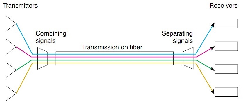
DWDM Technology
DWDM Networks

Figure 1: DWDM Networks

DWDM (Dense Wavelength Division Multiplexing) is an associate extension of optical networking. It can put data signals from different sources together on a single optical fiber pair, with each signal simultaneously carried on its own separate light wavelength. With DWDM, up to 160 wavelengths with a spacing of 0.8/0.4 nm (100 GHz/50 GHz grid) separate wavelengths or channels of data can be transmitted over a single optical fiber.

DWDM Networks Components

Conventionally, for DWDM networks, there are four devices showed as below that are commonly used by IT workers:

  • Optical transmitters/receivers
  • DWDM mux/demux filters
  • Optical add/drop multiplexers (OADMs)
  • Optical amplifiers transponders (wavelength converters)

DWDM Networks Over Long Distance Transmission Solutions

Scenario 1: 40 km Transmission
40km DWDM Network

Figure 2: 40km DWDM Network

For this case, the 80km DWDM SFP+ modules and 40ch DWDM Mux/Demuxs are recommended to use. Since the 80km DWDM SFP+ modules are able to support 10G transmission over 40 km, no additional device is needed under this scenario.

Scenario 2: 80 km Transmission
80km DWDM Network

Figure 3: 80km DWDM Network

Deploying this 80 km DWDM network, we will still use 80km DWDM SFP+ modules and 40ch DWDM Mux/Demuxs. The light source of 80km DWDM SFP+ modules might not be able to support such long transmission distance, as there might be a light loss during transmission. In this case, pre-amplifier (PA) is usually deployed before the location A and location B to improve the receiver sensitivity and extend signal transmission DWDM distance. Meanwhile, the dispersion compensation module (DCM) can be added to this link to handle the accumulated chromatic dispersion without dropping and regenerating the wavelengths on the link. The above diagram shows the deploying method of this 80km DWDM network.

Scenario 3: 100 km Transmission
100km DWDM Network

Figure 4: 100km DWDM Network

Under this scenario, the devices used in scenario 2 still need to remain. Since the transmission distance has been increased, the light power will be decreased accordingly. Besides that, you will also need to use booster EDFA (BA) to amplify the optical signal transmission of the 80km DWDM SFP+ modules.

By the way, if you want to extend DWDM transmission distance, you can read this post for solutions: Extend DWDM Network Transmission Distance With Multi-Service Transport Platform.

Factors to Consider in Deploying DWDM Networks

1. Being compatible with existing fiber plant. Some types of older fiber are not suitable for DWDM use. Currently, standard singlemode fiber (G. 652) accounts for the majority of installed fiber, supporting DWDM in the metropolitan area.

2. Having an overall migration and provisioning strategy. Because DWDM is capable of supporting massive growth in bandwidth demands over time without forklift upgrades, it represents a long-term investment. Your deployment should allow for flexible additions of nodes, such as OADMs, to meet the changing demands of customers and usages.

3. Network management tools. A comprehensive network management tool will be needed for provisioning, performance, monitoring, fault identification and isolation, and remedial action. Such a tool should be standards-based (SNMP, for example) and be able to interoperate with the existing operating system. For example, the FMT DWDM solutions from FS.COM are able to support kinds of network management, including NMU line-card, monitor online, simple management tool, and SNMP.

4. Interoperability issues. Because DWDM uses specific wavelengths for transmission, the DWDM wavelengths used must be the same on either end of any given connection. Moreover, other interoperability issues also need to be considered, including power levels, inter- and intra-channel isolation, PMD (polarization mode dispersion) tolerances, and fiber types. All these contribute to the challenges of transmission between different systems at Layer 1.

5. Strategy for protection and restoration. There might have hard failures (equipment failures, such as laser or photodetector, and fiber breaks) and soft failures such as signal degradation (for example, unacceptable BER). Therefore, you need to have a protection strategy while deploying a DWDM network.

6. Optical power budget or link loss budget. Since there might be an optical signal loss over the long distance transmission, it’s critical to have a link loss budget in advance.

Summary

Bringing great scalability and flexibility to fiber networks, the DWDM networks solutions obviously enjoys plenty of strengths, which is also proved to be future-proof. In this post, we make a revelation of the DWDM-based network over long distance transmission. Also, some tips for deploying a DWDM network has also been shared for your reference.

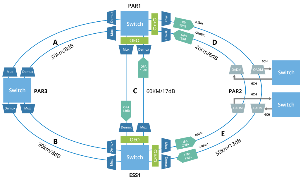
How to Light a DWDM Ring Beyond 10G?

Network layout nowadays is no longer limited by old rules created for early Ethernet networks. The technology and infrastructure devices available currently allow for different network topologies, including bus, star, ring and mesh networks. Each of them has its benefits and drawbacks and can be combined to suit application needs. This article emphasizes on the DWDM ring network configuration, illustrating the approaches to build a fiber ring beyond 10G.

What Is a DWDM Fiber Ring?

A fiber ring refers to the network topology in which each node connects to exactly two other nodes, forming a single continuous pathway for signals through each node. A ring configuration is designed to withstand a single failure. If there happens to be a failure, the system automatically reconfigures itself.

Similarly, a DWDM ring network includes fiber in a ring configuration that fully interconnects nodes. Two fiber rings are even presented in some systems for network protection. This DWDM  ring topology is commonly adopted in a local or a metropolitan area which can span a few tens of kilometers. Many wavelength channels and nodes may be involved in DWDM ring system. One of the nodes in the ring is a hub station where all wavelengths are sourced, terminated, and managed, connectivity with other networks takes place at this hub station. Each node and the hub have optical add-drop multiplexers (OADM) to drop off and add one or more designated wavelength channels. As the number of OADMs increases, signal loss occurs and optical amplifier is needed.

DWDM ring

How to Create a DWDM Fiber Ring Beyond 10G?

Assuming to build a higher than 10G optical ring using two strands of dark fibers, all nodes in this ring configuration are less than 10km apart and there are 8 nodes in total. Here we illustrate the options for achieving a DWDM ring beyond 10G.

20G Fiber Ring

For a 20G ring, the configuration is rather simple. There is no need for an OADM or Mux/Demux, it is recommended to use an Ethernet switch with two SFP+ ports and a pair of BIDI SFP+ optics.

Items Description
S5800-48F4S High Performance Data Center Switch (48*1GE+4*10GE)
10GBASE-BX SFP+ Generic Compatible 10GBASE-BX SFP+ 1270nm-TX/1330nm-RX 10km DOM Transceiver
10GBASE-BX SFP+ Generic Compatible 10GBASE-BX SFP+ 1330nm-TX/ 1270nm-RX 10km DOM Transceiver
40G Fiber Ring

There are three options for creating a 40G DWDM ring.

1. Use a switch with QSFP+ ports, and using QSFP+ optics in accordance. This can be the most cost-effective option for 40G if you have no future plan for more than 40G on the ring.

Items Description
S5850-48S6Q High Performance Data Center Switch (48*10GE+6*40GE)
40GBASE-LR4 Generic Compatible 40GBASE-LR4 and OTU3 QSFP+ 1310nm 10km LC Transceiver for SMF

2. Use four 10G SFP+ optics and a CWDM OADM. You could even scale up to 18 channels giving you a 180G ring if you used all 18 CWDM channels and had that large of an OADM or Mux/Demux. First, four channels with lower cost SFP+ optics, wavelength 1270nm through 1310nm. Then the next 14 channels 1350nm to 1610nm adopt SFP+ with relatively higher cost. You would need a SFP+ port per channel on both ends, and a passive CWDM OADM.

Items Description
CWDM OADM Single Fiber/ Dual Fiber CWDM OADM, East and West
10GBASE-LR SFP+ Generic Compatible 10GBASE-LR SFP+ 1310nm 10km DOM Transceiver
10GBASE-ER SFP+ Generic Compatible 10GBASE-ER SFP+ 1550nm 40km DOM Transceiver

3. Use 10G DWDM SFP+ optics and a DWDM OADM. You can choose less expensive 100Ghz optics that have up to 40 or 44 channels or the expensive 50Ghz optics that can reach up to 80 or 88 channels.

Items Description
DWDM OADM Single Fiber/ Dual Fiber DWDM OADM, East and West
10G DWDM SFP+ Generic C40 Compatible 10G DWDM SFP+ 100GHz 1545.32nm 40km DOM Transceiver
10G DWDM SFP+ Generic H50 Compatible 10G DWDM SFP+ 50GHz 1537nm 40km DOM Transceiver
100G Fiber Ring

As for a 100G fiber ring, you can count on Ethernet switches that have 100G QSFP28 uplink ports, along with 100G QSFP28 optics. This would allow a 100G connection each way around the ring.

Items Description
S5850-48S2Q4C Carrier Grade 100G-uplink Switch (48*10GE + 2*40GE + 4*100GE)
100GBASE-LR4 Generic Compatible QSFP28 100GBASE-LR4 1310nm 10km Transceiver
Conclusion

Fiber ring enables more reliability and survivability: if a single link failure should occur – the traffic can simply be sent the other way around the ring. With the pervasiveness of Ethernet technology, the ring architecture is widely adopted to construct a Metropolitan Area Network (MAN), Metro-Ethernet service and school district that uses municipal fiber pathways. Several options for creating fiber ring beyond 10G are presented, along with the optical components needed. Hope this could be informative enough.

Related Article: Complete Analysis on DWDM Technology

40G Transceiver vs 100G Transceiver: Which One Is Worth the Investment?

Today, the trend for high-speed data transmission and high-bandwidth is overwhelming. Some years ago, people had witnessed upgrading from 10Mbps Ethernet to 100Mbps Ethernet. And the migration from 1G to 10G was happened not very long ago. But now, whether you believe it or not, prepared or not prepared, 40G and 100G have already on the way. Meanwhile, 40G transceiver and 100G transceiver are widely deployed among data center managers and IT engineers. 40G transceiver vs 100G transceiver, which one is worth the investment.

The Rise of 100G

To begin with, it has to be made clear that the market trend is 100G Ethernet, which will eventually become the mainstream in the future. The strong demand in 100G Ethernet is being driven by cloud services and hyper-scale data centers. And there is a demand for lower-priced 100G pluggable transceivers from data center customers. Currently, the market transition to 100GE is in full swing, fueled primarily by the seemingly insatiable need for networking bandwidth by hyper-scale data centers and cloud services. As it has been shown in the picture below, 100G Ethernet transceivers will exceed 15 million units a year.

100G market

This tremendous growth in deployments by a small number of key customers, together with a large number of suppliers competing for these orders, will undoubtedly drive down the cost of 100GE modules rapidly. It is predicted that the cost of 100G optical transceiver is expected to decline by 75% in the next couple of years. In the meantime, Facebook has publicly set a target cost of $100 for a 100G transceiver with a reach of less than 2km. While the Facebook target appears to be years away, we believe that a 70% cost reduction in 2 years is possible. By that time, the 100G transceiver will be more affordable.

Why not 40G?

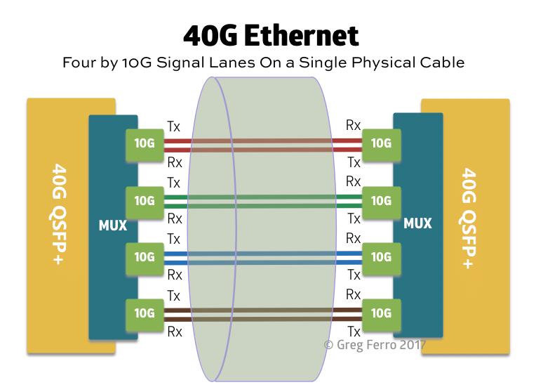
If you ask me why 40G Ethernet will be obsolete? The short answer is “cost”. From the technical point, The primary issue lies in the fact that 40G Ethernet uses 4x10G signalling lanes. On UTP, 40G uses 4 pairs at 10G each. Early versions of the 40G standard used 4 pairs, but rapid advances in manufacturing developed a 4x10G WDM on a single fiber optic pair. Each 40G SFP module contains a silicon chip that performs multiplexing so that the switch see 40 gigabits in and 40 gigabits out. It’s similar to Coarse Wave Division Multiplexing when using fiber. When you buy a 40G cable or QSFP, you are paying for the cost of the chip and software, plus the lasers, etc. When using 25/50/100G, the “lane speed” is increased to 25 gigabits per second. For 100G Ethernet, there are four 25G signalling lanes. It’s cheaper to buy 100G with four lanes rather than 40G with a four-lane MUX.

40GEthernet

Scale up to 100G with FS 100G Optics Solution

As one of the leading providers in optical communication , FS provides customers with 100G optics that are manufactured at the highest quality of standards in the industry, including QSFP28, CFP, CFP2, CFP4, 100G patch panels, 100G switches, etc. Part of the products are listed as follow:

Model ID Description    Price

48862

Juniper JNP-QSFP-100G-SR4 Compatible 100GBASE-SR4 850nm 100m Transceiver

   US$  269

48354

Cisco Compatible QSFP28 100GBASE-SR4 850nm 100m Transceiver

   US$  269

65228

Juniper Networks CFP-100GBASE-SR10 Compatible 100GBASE-SR10 850nm 150m Transceiver

   US$  1,500

Summary
100G Ethernet are racing to market and will finally takeover the 40G market. FS provides both 40G transceiver and 100G transceiver for your network deployment. They are compatible with major brands, like Cisco, Brocade, Juniper, Dell, Arista, etc. If you had any inquiry, you can kindly visit www.fs.com.

Related Article: Preparation for 40G/100G Migration

Introduction to WDM Transponder

With the development of wavelength-division multiplexing (WDM) technology, the network traffic volume is increasing and the demand for more network bandwidth is also on the rise. By converting the operating wavelength of the incoming bitstream to an ITU-compliant wavelength, WDM transponder serves as a key component in WDM system. As an important technology in the fiber optical network, WDM is moving beyond transport to become the basis of all-optical networking. And how to optimize WDM network has always been a hot topic. The transponder is a device to optimize the performance of WDM network, which plays an important in the whole system of WDM network. This article will introduce you the information on WDM transponders.

What Is WDM Transponder?

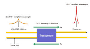
Also called as an OEO (optical-electrical-optical) transponder, a WDM transponder unit is an optical-electrical-optical wavelength converter, which has been widely adopted in a variety of networks and applications. The picture below shows us how a bidirectional transponder works. In this picture, the transponder is located between a client device and a DWDM system. And we can see clearly that, from left to right, the transponder receives an optical bitstream operating at one particular wavelength (1310 nm), and then converts the operating wavelength of the incoming bitstream to an ITU-compliant wavelength and transmits its output into a DWDM system. On the receive side (right to left), the process is reversed. The transponder receives an ITU-compliant bitstream and converts the signals back to the wavelength used by the client device.

WDM transponder

The Application of a WDM Transponder

According to its function, the application of WDM transponders can be classified into the following types.

  • Wavelength Conversion. It is known to us that when a CWDM Mux/Demux or DWDM Mux/Demux is added into a WDM network, there is a requirement to convert optical wavelengths like 850nm, 1310nm and 1550nm to CWDM or DWDM wavelengths. Then the OEO transponder comes to assist. The OEO transponder receives, amplifies and re-transmits the signal on a different wavelength without changing the signal content.
  • Fiber Mode Conversion. Multimode fiber optic cables (MMF) are often used in short distance transmission, while single-mode fiber optic cables (SMF) are applied in long optical transmission. Therefore, in some network deployment, considering the transmission distances, MMF to SMF or SMF to MMF conversions are needed. WDM transponders can convert both multimode fiber to single-mode fiber and dual fiber to single fiber.
  • Signal Repeating. In long haul fiber optic transmission, WDM transponder also can work as repeaters to extend network distance by converting wavelengths (1310nm to 1550nm) and amplifying optical power. The OEO converters convert the weak optical signals from the fiber into electrical signals, and regenerate or amplify, then recover them into strong optical signals for continuous transmission.
WDM Transponder and FMT Solution

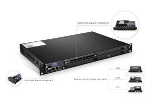
At FS, OEO transponders are made into small plug-in cards to be used on the FMT platform. FMT platform makes devices like EDFA, OEO, DCM, OLP and VOA into plug-in cards and provides standard rack units as well as free software to achieve better management and monitoring. In addition, FMT series products like OEO, DCM and OLP also have higher performance than that of old ones. FMT series OEO transponder can convert optical signals into DWDM wavelengths, reducing the fault risk caused by high power consumption of DWDM fiber optic transceiver. Since the OEO transponder is made into small plug-in card in the FMT platform, it only occupies one slot in the special designed chassis when installed, thus saving a lot of space. In addition, all these FMT plug-in cards, including OEO, in a rack unit share the same power source and support hot plug & play operation. And they can be inserted or removed flexibly in the racks for DWDM networking.

FMT

Conclusion

Since the OEO or WDM transponder plays an important role in WDM network, such as receiving, amplifying and re-transmitting the signal on a different wavelength, adding an OEO transponder into the WDM network is very essential. The OEO transponders in our FMT series are made into small plug-in cards with high quality to ensure good transmission performance. For more information on our FMT system, please visit www.fs.com.

Related Article: The Versatile Fiber Optic Transponder (OEO) in WDM System

Brief Introduction to EDFA

In fiber optic communication systems, problems arise from the fact that no fiber material is perfectly transparent. The visible-light or infrared beams carried by a fiber are attenuated as they travel through the material. This necessitates the use of optical amplifiers. And EDFA (Erbium Doped Fiber Amplifier) is a representative one in the optical amplifier. There is one saying that EDFA is the most popular optical amplifier in optical network communications. Next, we will begin with the definition of EDFA.

The Definition of EDFA

An EDFA, also called optical amplifier or an erbium-doped fiber amplifier or erbium amplifier, is an optical or IR (Infrared Radiation) repeater that amplifies a modulated laser beam directly, without opto-electronic and electro-optical conversion. The device uses a short length of optical fiber doped with the rare-earth element erbium. When the signal-carrying laser beams pass through this fiber, external energy is applied, usually at IR wavelengths. This so-called pumping excites the atoms in the erbium-doped section of optical fiber, increasing the intensity of the laser beams passing through. The beams emerging from the EDFA retain all of their original modulation characteristics, but are brighter than the input beams.

Three Major Applications for Optical AmplifierThree Major Applications for Optical Amplifier

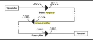
The above picture illustrates the three major applications for optical fiber amplifiers: booster, in-line amplifier, and pre-amplifier. These applications are described in more details below:

Booster Amplifier

Booster amplifiers are placed directly after the optical transmitter. In this application, booster amplifier is adopted to compensate for the losses of optical elements between the laser and optical fibers so that the increased transmitter power can be used to go further in the link.

In-line Amplifier

In-line amplifiers or in-line repeaters are placed along the transmission link to compensate for the losses incurred during propagation of optical signal. They take a small input signal and boost it for re-transmission down the fiber. Here it should also be pointed out that to control the signal performance and the noise added by the EDFA is important, because noise added by amplifier will limit the system length.

Pre-amplifier

Pre-amplifiers are placed just before the receiver to increase the signal level before the photodetection takes place in an ultra-long haul system so as to improve receiver sensitivity. By placing a pre-amplifier, a much larger signal can be presented to the receiver, thus easing the demands of the receiver design.

Top EDFA Products Overview

By now, you should have a basic idea of what an EDFA is and what it is used for, next I will introduce you some truly excellent EDFA products on the market.

Type
Description
22dBm Output Booster DWDM EDFA C-band 24dB Gain, 1U Rack Mount
16dBm Output Mid-stage DWDM EDFA C-band 26dB Gain, Plug-in Card for FMT Multi-Service Transport System
17dBm Output Mid-stage DWDM EDFA C-band 17dB Gain, Plug-in Card for FMT Multi-Service Transport System
Conclusion

Of the various technologies available for optical amplifiers, EDFA technology is the most advanced, and consequently the vast majority of optical amplifiers are designed based on this technology. In addition, the combination of reliable performance and relatively low cost allows EDFA to be widely deployed in modern optical networks.