Tag Archives: Ethernet switches

TAP Aggregation Switch: Key to Monitor Network Traffic

For network professionals, Ethernet switches have already been used very commonly in network design. In order to ensure network security and monitor the performance of the standard Ethernet switches, network test access port (TAPs) have emerged as one of the primary sources for data monitoring or network traffic monitoring. What is network TAP or TAP aggregation switch, and how to deploy it for network traffic monitoring? This post will give you the answer.

What Is TAP Aggregation Switch or Network TAP?

A network tap is a hardware device which provides an approach to access the data flowing across a network. It functions by flow copy or aggregation, thus it’s also called TAP aggregation switch. TAP aggregation switch works by designating a device to allow the aggregation of multiple TAPs and to connect to multiple monitoring systems. In this process, all the monitoring devices are linked to specific points in the network fabric that handle the packets that need to be observed. In most cases, a third party TAP aggregation switch monitors the traffic between two points in the network. If the network between point A and B consists of a physical cable, a network TAP or TAP aggregation switch might be the best way to accomplish this monitoring. TAP aggregation switch deployed between point A and B passes all traffic through unimpeded, but it also copies that same data to its monitor port, which could enable a third party to listen.

Deployment Scenario of TAP Aggregation Switch

TAP aggregation switches or network TAPs can be extremely useful in monitoring traffic because they provide direct inline access to data that flows through the network. The following part illustrates the typical applications of TAP aggregation switches in data center and carrier network.

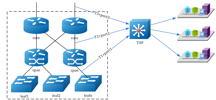
    • Application in Data Center
      As shown in the figure below, user can enable the timestamp and source port label function of TAP devices. The server cluster can access the exact packet process time in each data center layer via source port and timestamp message carried by the packets. From port1, port2, port3, user can distinguish the devices that the streams come from. Through T1, T2 and T3, packets forward latency of each device can be calculated, according to which users can find out the bottleneck during packet forwarding for the further optimization of data center network.

TAP Aggregation Switch for Data Center

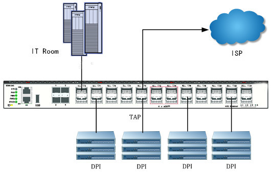
  • Application in Carrier Network
    TAP aggregation switch can also be used to assist DPI (Deep Packet Inspection) in carrier networks. As illustrated below, TAP aggregation switch is applied to forward flows of carrier at internet access point and sends a mirrored copy of the packet flow to DPI device at the same time. The DPI device is for traffic analysis, once a virus on website or illegal information has been monitored, the flows will be blocked by a five elements table sent from management channel between DPI and TAP.

TAP Aggregation Switch for Carrier Network

FS TAP Aggregation Switches Solution

FS network TAPs or TAP aggregation switches deliver security, visibility and traffic analysis for high density, non-blocking 1G/10/40/100GbE networks at any scale with advanced traffic management capabilities for lossless monitoring of network traffic. They can cost-effectively and losslessly monitor all data center network traffic, while capturing and analyzing only the traffic that is needed. The table below lists FS T5800 and T8050 series TAP aggregation switches.

TAP Aggregation
Key Features
  • Standard 1U 19’’ rack mountable, 240 Gbps switching capability
  • 8×10/100/1000 Base-T Ethernet Ports, 8×1000 Base-X SFP Ports (Combo)
  • 12x10GE SFP+ Ports
  • Dual modular power supply
  • Standard 1U 19’’ rack mountable
  • 4x10GE SFP+ Ports(Combo)
  • 20x40GE QSFP+ Ports
  • 4x100GE QSFP28 Ports
  • Dual modular power supply
  • Standard 1U 19’’ rack mountable
  • 48x10GE SFP+ Ports
  • 2x40GE QSFP+ Ports
  • 4x100GE QSFP28 Ports
  • Dual modular power supply
  • Standard 1U 19’’ rack mountable
  • 48x10GE SFP+ Ports
  • 6x40GE QSFP+ Ports
  • Dual modular power supply
  • Standard 1U 19’’ rack mountable
  • 32x10GE SFP+ Ports
  • 2x40GE QSFP+ Ports
  • Dual modular power supply

Conclusion

TAP aggregation switches are crucial to any network monitoring plan because they offer an uncensored view of all network traffic. With FS TAP aggregation switches, customers can transform opaque data center traffic into comprehensive visibility for security threat detection, service availability monitoring as well as traffic recording and troubleshooting. Apart from TAP aggregation switches, the standard Ethernet switches including Gigabit switches, 10gb switches, 40gb switches and 100gb switches are also available for your choice.

Ethernet Switches: to Stack or Not to Stack?

Over past years, stacking has escalated from a premium feature to a core constituent of an Ethernet switch. Stack switch has become more and more popular among users. When it comes to network design, you may often face two challenges: maximizing scalability and optimizing performance. Finding the right balance can be tricky. This is why you’ve considered stacking or not stacking when managing your Ethernet switches.

What Is Switch Stacking or Stack Switch?

Stack switch is a type of switch designed to be stacked on top of one another. Stackable Ethernet switch is now well established as a stable, standards-based connectivity technology to efficiently handle and manage bandwidth-hungry applications. Stacking allows you to manage multiple switches as a single entity and provides increased bandwidth between the switches. Stack switches can be placed in networking closets and stand alone as a whole unit. The feature sets of stack switch vary depending on vendor and platform. Most stack switches support advanced functions like QoS, multicasting, and VLAN management. For instance, the following FS S3800-24T4S stack switch gigabit is a 24-Port 10/100/1000BASE-T Gigabit switch with QoS flow control and IP subnet-based VLAN. It supports up to 4 switches stacking and up to 96 Gigabit ports and 8 10G SFP+ ports per physical stack, providing up to 512Gbps total switching capacity for the network.

stack switch

To Stack or Not to Stack – Think Twice Before Buying

Whether an enterprise outfits its wiring closets with stack switch or not will depend on what services are needed and how much redundancy is required at the network edge. Stacking multiple switches allows for efficiency and ease of management when you do it right. The switch capacity of a stack is the total port density of the combined switches that are stacked together. For example, when you stack four 24-port switches, you will get one large 96-port switch when it comes to configuration. All these switches in the stack share a single IP address for remote administration instead of each stack unit having its own IP address.

In a small business where access to data and resources are critical, it is a wise option to choose stackable switches because they can significantly reduce downtime and make your network more resilient. In mission critical networks, if a switch within the stack went down, another switch would take over, ensuring that your network remains up and running uninterruptedly. In this way, stackable switches provide additional protection and redundancy for your network. Moreover, you can replace the breakdown switch in the stack without having your network offline for extended periods and impacting employee productivity in the process.

Approaches to Stack Ethernet Switches

Generally, there are mainly two ways to stack multiple network switches into a group. For stack switch with dedicated stacking ports, a stack cable is used to realize switch stacking among them. But only approved cable can be used as stack cable, or else it would cause damage to the switches. The other approach is to use the uplink ports on the switch to connect each switch together in the stacking system. Most stack switches on the market today can be stacked using several types of Ethernet ports including 10GBASE-T copper port, 10G SFP+ fiber port and 40G QSFP+ port as an uplink. For example, FS S3800-24F4S gigabit ethernet switch uses 4 10G SFP+ ports as uplink ports to stack between switches. Up to four of the same type of models can be stacked together via SFP+ transceivers (with fiber patch cable) or DAC cables. Here’s the video to show you how to stack FS S3800 series switches step by step.

FS.COM Stackable Managed Switch List

Model Switch Class Switching Capacity Gigabit RJ45 Ports SFP Ports SFP+ Ports Combo Ports Price
S3800-24T4S Layer2+ 128Gbps 24 N/A 4 N/A US$369
S3800-24F4S Layer2+ 128Gbps N/A 20 4 4 US$389
S5900-24S Layer3 480Gbps N/A N/A 24 N/A US$1999

Note: Please be careful about Ethernet switches in the market which are sold as “stackable” when they merely offer a single user interface, or central management interface, for getting to each individual switch unit. This approach is not stackable, but really “clustering”. You still have to configure every feature such as ACLs, QoS, Port mirroring, etc, individually on each switch.

Conclusion

As your business grows, is your network prepared to grow accordingly? Stack switches have become extremely popular for good reasons. They can simplify management and enhance switching capacity for easy network expansion. But for most customers, achieving super high availability may not be the goal. Then standalone switches are already enough for you rather than stack switches. Thus the pay-as-you-grow stack switch model is suitable for those who need flexibility, not only in their physical network, but also in the amount of traffic that is going through it.

Related Article: FS S5900-24S Stackable Switch: Affordable Option for Network Expansion

How to Light a DWDM Ring Beyond 10G?

Network layout nowadays is no longer limited by old rules created for early Ethernet networks. The technology and infrastructure devices available currently allow for different network topologies, including bus, star, ring and mesh networks. Each of them has its benefits and drawbacks and can be combined to suit application needs. This article emphasizes on the DWDM ring network configuration, illustrating the approaches to build a fiber ring beyond 10G.

What Is a DWDM Fiber Ring?

A fiber ring refers to the network topology in which each node connects to exactly two other nodes, forming a single continuous pathway for signals through each node. A ring configuration is designed to withstand a single failure. If there happens to be a failure, the system automatically reconfigures itself.

Similarly, a DWDM ring network includes fiber in a ring configuration that fully interconnects nodes. Two fiber rings are even presented in some systems for network protection. This DWDM  ring topology is commonly adopted in a local or a metropolitan area which can span a few tens of kilometers. Many wavelength channels and nodes may be involved in DWDM ring system. One of the nodes in the ring is a hub station where all wavelengths are sourced, terminated, and managed, connectivity with other networks takes place at this hub station. Each node and the hub have optical add-drop multiplexers (OADM) to drop off and add one or more designated wavelength channels. As the number of OADMs increases, signal loss occurs and optical amplifier is needed.

DWDM ring

How to Create a DWDM Fiber Ring Beyond 10G?

Assuming to build a higher than 10G optical ring using two strands of dark fibers, all nodes in this ring configuration are less than 10km apart and there are 8 nodes in total. Here we illustrate the options for achieving a DWDM ring beyond 10G.

20G Fiber Ring

For a 20G ring, the configuration is rather simple. There is no need for an OADM or Mux/Demux, it is recommended to use an Ethernet switch with two SFP+ ports and a pair of BIDI SFP+ optics.

Items Description
S5800-48F4S High Performance Data Center Switch (48*1GE+4*10GE)
10GBASE-BX SFP+ Generic Compatible 10GBASE-BX SFP+ 1270nm-TX/1330nm-RX 10km DOM Transceiver
10GBASE-BX SFP+ Generic Compatible 10GBASE-BX SFP+ 1330nm-TX/ 1270nm-RX 10km DOM Transceiver
40G Fiber Ring

There are three options for creating a 40G DWDM ring.

1. Use a switch with QSFP+ ports, and using QSFP+ optics in accordance. This can be the most cost-effective option for 40G if you have no future plan for more than 40G on the ring.

Items Description
S5850-48S6Q High Performance Data Center Switch (48*10GE+6*40GE)
40GBASE-LR4 Generic Compatible 40GBASE-LR4 and OTU3 QSFP+ 1310nm 10km LC Transceiver for SMF

2. Use four 10G SFP+ optics and a CWDM OADM. You could even scale up to 18 channels giving you a 180G ring if you used all 18 CWDM channels and had that large of an OADM or Mux/Demux. First, four channels with lower cost SFP+ optics, wavelength 1270nm through 1310nm. Then the next 14 channels 1350nm to 1610nm adopt SFP+ with relatively higher cost. You would need a SFP+ port per channel on both ends, and a passive CWDM OADM.

Items Description
CWDM OADM Single Fiber/ Dual Fiber CWDM OADM, East and West
10GBASE-LR SFP+ Generic Compatible 10GBASE-LR SFP+ 1310nm 10km DOM Transceiver
10GBASE-ER SFP+ Generic Compatible 10GBASE-ER SFP+ 1550nm 40km DOM Transceiver

3. Use 10G DWDM SFP+ optics and a DWDM OADM. You can choose less expensive 100Ghz optics that have up to 40 or 44 channels or the expensive 50Ghz optics that can reach up to 80 or 88 channels.

Items Description
DWDM OADM Single Fiber/ Dual Fiber DWDM OADM, East and West
10G DWDM SFP+ Generic C40 Compatible 10G DWDM SFP+ 100GHz 1545.32nm 40km DOM Transceiver
10G DWDM SFP+ Generic H50 Compatible 10G DWDM SFP+ 50GHz 1537nm 40km DOM Transceiver
100G Fiber Ring

As for a 100G fiber ring, you can count on Ethernet switches that have 100G QSFP28 uplink ports, along with 100G QSFP28 optics. This would allow a 100G connection each way around the ring.

Items Description
S5850-48S2Q4C Carrier Grade 100G-uplink Switch (48*10GE + 2*40GE + 4*100GE)
100GBASE-LR4 Generic Compatible QSFP28 100GBASE-LR4 1310nm 10km Transceiver
Conclusion

Fiber ring enables more reliability and survivability: if a single link failure should occur – the traffic can simply be sent the other way around the ring. With the pervasiveness of Ethernet technology, the ring architecture is widely adopted to construct a Metropolitan Area Network (MAN), Metro-Ethernet service and school district that uses municipal fiber pathways. Several options for creating fiber ring beyond 10G are presented, along with the optical components needed. Hope this could be informative enough.

Related Article: Complete Analysis on DWDM Technology