Category Archives: Fiber Optic Transmission

400G Transceiver, DAC, or AOC: How to Choose?

Due to the increasing growth in the demand for data centers and cloud computing, enterprises are eager for data centers with higher speed, larger bandwidth, and lower latency. In this case, 400G Ethernet has become an inevitable trend in data centers. With the advent of 400G technology, there are typically two options for 400G data center connectivity: 400G transceivers and 400G DAC/AOC.

400G Transceivers

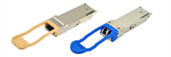
400G transceivers are common solutions for 400G data center interconnection. According to different 400G transceiver form factors, there are CFP8, QSFP-DD, OSFP, COBO, etc., of which the most common type is QSFP-DD. These transceivers are different from each other in terms of transmission distance, connector, media and so on.

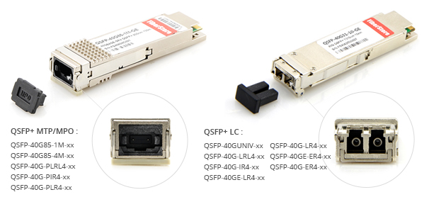
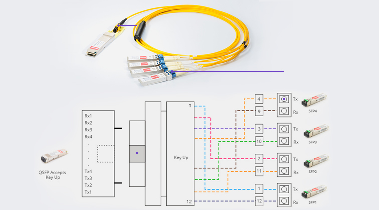
Usually, the SR8 module uses an MPO-16 connector to connect to 8 fiber pairs, realizing 400G transmission. The DR4 / XDR4 / PLR4 modules use an MPO-12 connector to connect to 4 fiber pairs. Unlike the SR8 and DR4, the FR4 optical modules use a duplex LC optical connector. And the FR8 modules (also called 2FR4 modules) use a dual CS connector to connect to 2 fiber pairs.

400G Cables: 400G DAC & AOC

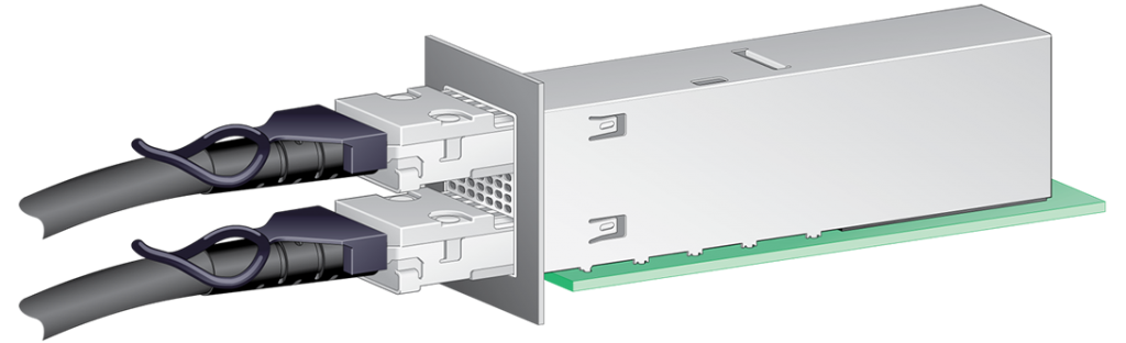
400G Direct Attached Cable (DAC) is suitable for very short-distance data center interconnection and it is cost-efficient. Besides, it uses copper cable as the transmission media. Typically, there are two types of DACs: passive copper cables for distance from 0 to 5m and active copper cables for distance from 5 to 15m.400G Direct Attached Cable

Different from 400G DAC, 400G Active Optical Cable (AOC) uses fiber optical fiber as the transmission media. It is equivalent to using transceivers and separate cables. Besides, 400G AOCs support longer distance transmission than DACs, which can be up to 100m. They are also lighter and smaller than DACs, but they are more costly. Unlike DACs, AOCs are not affected by Electromagnetic Interference (EMI). You can check this article for more details on the 400G DAC and AOC.400G Active Optical Cable

Apart from 400G to 400G DAC/AOC, there are also 400G DAC/AOC breakout cables, such as 400G QSFP-DD to 4x100G QSFP56 DAC breakout cable, 400G QSFP-DD to 2x200G QSFP56 breakout AOC cable, and 400G QSFP-DD to 8x50G SFP56 DAC Breakout Cable. In this article, we’ll focus on 400G to 400G connection over 400G DAC/AOC.

Common 400G Transceiver/DAC/AOC Scenarios

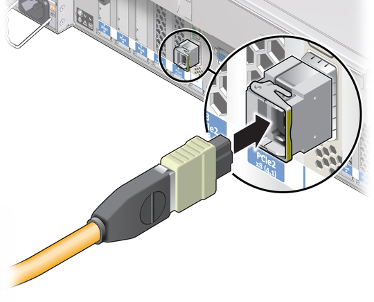
Connectivity from ToR Switch to Server (Up to 2.5m)

400G DAC Connectivity

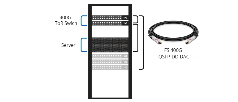
400G DAC is the perfect solution for linked switches and servers inside racks. As shown in the figure above, 400G QSFP-DD DAC is used to connect 400G ToR switch and server in a 42U server cabinet. Because the height of the 42U server cabinet is only about 2 meters and 400G DAC is also cost-efficient, the 400G DAC becomes an ideal solution for short-distance transmission inside cabinet.

Connectivity from EoR Switch to Server (Up to 30m)400G AOC Connectivity

The 400G AOC usually connects switches and servers between racks in a data center. As the picture above shows, the 400G EoR switch is connected to the server rack and aggregation rack through 400G QSFP-DD AOC. Since the 400G AOC uses optical fiber as the transmission media, it can achieve longer distance transmission and higher bandwidth than the 400G DAC. Besides, it is also used to connect separate switches to create a larger switch architecture.

Connectivity from ToR Switch to Server (Up to 100m)400GBASE-SR8 QSFP-DD transceivers connection

400GBASE-SR8 QSFP-DD transceivers can be used for leaf-spine switches interconnection and the transmission distance can reach 100m over OM4 MMF with MTP/MPO-16 connector.

Connectivity from ToR Switch to Server (Up to 150m)400GBASE-SR4.2 QSFP-DD transceivers connection

Different from 400GBASE-SR8 QSFP-DD transceivers, the 400GBASE-SR4.2 QSFP-DD transceivers support 150m distance transmission over MPO/MTP-12 OM5 MMF.

Connectivity from ToR Switch to Server (Up to 500m)400GBASE-DR4 QSFP-DD transceivers connection

400GBASE-DR4 QSFP-DD transceivers support up to 500m transmission distance over OS2 SMF with MPO/MTP-12 connector.

Data Center Interconnection (up to 2-120km)Data Center Interconnection

  • Up to 2km: Usually, the data center interconnection needs transceivers that support longer distance and higher bandwidth transmission. 400GBASE-FR4 QSFP-DD transceivers support link lengths of up to 2km over OS2 SMF with duplex LC connector.
  • Up to 10km: For data center interconnection over 2km, 400GBASE-LR8 QSFP-DD transceiver is a better choice. It can support data transmission distances of up to 10km over OS2 SMF.
  • Up to 40km: 400GBASE-ER8 QSFP-DD enables link lengths of up to 40km over OS2 SMF with duplex LC connectors. Besides, it also features low-power, high-density and high-speed, which is a high-efficient option for 400G data center interconnection. However, it uses EML laser, APD detector, and also needs to use Mux combiner and Demux splitter, which leads to high cost.
  • Up to 120km: As for hyperscale data center interconnection, only 400G-ZR CSFP Coherent optical modules can meet the demands, supporting OS2 SMF transmission distances up to 120km.

Conclusion

In conclusion, 400G transceivers and 400G AOC and DAC cables are effective choices for the 400G data center connectivity. Both 400G AOC and DAC are more suitable for short distance transmission. However, the 400G AOC supports higher data transfer speed, while the 400G DAC is more cost-efficient. As for 400G transceivers, the application scenarios are more abundant. Data center operators should make appropriate choices based on their actual needs.

Article Source:

https://community.fs.com/blog/400g-transceiver-dac-or-aoc-how-to-choose.html

Related Articles:

https://community.fs.com/blog/faqs-on-400g-transceivers-and-cables.html
https://community.fs.com/blog/fs-400g-cabling-solutions-dac-aoc-and-fiber-cabling.html

Double Density QSFP (QSFP-DD) Is Coming

Recently the building of QSFP-DD (Multi Source Agreement) Group has excited optical communication industry. This group, including 13 members which are all the leading vendors in the industry, like Cisco, Brocade and Finisar, aims to create a upgraded version of QSFP transceiver, which is called QSFP-DD ( double density QSFP) and will be able to support 200G/400G Ethernet.

Introduction

The QSFP-DD is similar to the current QSFP. But there are many differences between the current QSFP. The reason why the new transceiver is called “double density” is related to the current 100G QSFP28 transceivers. The “double density” means the doubling of the number of high-speed electrical interfaces that the module supports compare to regular QSFP28 module.

QSFP-DD transceiver

QSFP-DD and QSFP28

We can understand the QSFP-DD better by comparing it with the current 100G QSFP28 module. QSFP28 transceiver is a four-channel transceiver which is able to transmit and receive 100G per second simultaneously. With the advantages of high speed and low power, QSFP28 transceiver is becoming more popular than other 100G transceivers like CFP2 and CFP4. The 100G QSFP28 transceiver is implemented with four lanes with each supporting data rate of 25G.

The working principle of QSFP-DD is similar with 100G QSFP28 transceiver. The QSFP-DD MSA group will increase the lane to eight. There will be a row of contacts providing for an eight lane electrical interface in QSFP-DD. If modulated by NEZ, each lane of the QSFP-DD can support data rate up to 25G, thus, it can support a total data rate of 200G. If modulated by PAM4, it can support data rate up to 400G with each lane supporting data rate of 50G. The MSA group also announced that the QSFP-DD can enable up to 14.4Tbps aggregate bandwidth in a single switch slot, which can definitely satisfy the increasing need for higher bandwidth.

Another great feature of QSFP-DD is that its system will be backwards compatible, allowing them to support existing QSFP modules and provide flexibility for end users and system designer. This means the data center could save a considerable sum of money in the future upgrading.

Future and Present

The appearance of QSFP28 transceiver has changed the regular development road map of Ethernet. The regular upgrade road is 10G to 40G and then 100G. While the QSFP28 transceiver has changed it from 25G directly to 100G. The road map of this QSFP-DD is also drawing our attention. It is predicted that it will become a useful family of modules for the industry with application at greater than 400G. Meanwhile, there is no efforts underway to define these new speeds but it is expected that QSFP-DD will have a roadmap that supports.

qsfp28 transceiver

Any way, no matter where the QSFP-DD lead our Ethernet to, it is good news for our future networking system. The creating of this new module will still need some time. For now, many data centers are considering about upgrading their data center with 100G QSFP28 transceivers. And there are a variety of switches which support QSFP28 interfaces on the market. However, 100G QSFP28 transceiver is still not cheap in the current market. For example, the price of a 100GBASE-SR4 QSFP28 transceiver is generally more than $2000.00. However, in FS.COM, supported by OEM, the price is much more favorable. A 100GBASE-SR4 QSFP28 transceiver only cost $650.00 in FS.COM. The following chart is detailed information of 100G QSFP28 transceivers in FS.COM.

FS P/N Form Type Data Rate Wavelength Max Cable Distance Interface Cable Type DOM Support
100G QSFP28-SR4 QSFP28 103.1 Gbps 850 nm 100 m MPO (MTP12) MMF Yes
100G QSFP28-LR4 QSFP28 103.1 Gbps 1310 nm 10 km LC Duplex SMF Yes

For more details, please contact us at sales@fs.com or visit FS.COM.

Related Articles: 40GBASE QSFP+ AOC VS 40GBASE SR4 QSFP+ Transceiver

                              40G Transceiver Module: QSFP+ Module And CFP Module

How to Select the Right Fiber Patch Cable for 40G QSFP+ Transceiver?

It is clear that most servers in data center can support Ethernet transmission of 40G, and 40G QSFP+ transceivers are considered to be the most economical solution for 40G transmission in data center. However, to make all these devices run normally and effectively, fiber patch cables must be used to connect the fiber optic transceivers which are plugged in Ethernet switches shown in the following picture. As the structure of 40G transmission is more complex than ever, the select of patch cords for 40G transceiver becomes more difficult. This article will focus on how to select the proper patch cords for 40G QSFP+ transceivers in details.

switch connection

Numerous things need to be taken into consideration for proper selecting the fiber patch cables for 40G QSFP+ transceivers in practical cabling. However, several factors should always be considered: the cable type of the patch cords, the connector attached on the ends of the patch cords, and the ports of the switches that need to be connected.

For the first factor to be considered is cable type. This is because of the transmission characteristic optical signals of the fiber optic. Optical signals performs different over different wavelength. And optical signals with the same wavelength performs totally different when they run through different types of cables.

A question that people might come across can illustrate the above point well. Can a 40GBASE universal QSFP+ transceiver working on wavelength of 850nm be used with OM1 patch cords? Usually, signals with wavelength of 850nm are transmitted over short distance. Thus selecting a multimode fiber patch cords would be more economical. However, OM1 patch cords, which are ususally suggested for 100Mb/s and 1000Mb/s, cannot support 40G transmission and the quality of the 40G transmission is bad. This is because the transmission distance reduced as the data rate raised. For this case, OM3 and OM4—the optimized multimode fiber optic cables for 40G transmission in short distance are suggested. OM3 can support 40G transmission up to 100 meters and OM4 can support 40G transmission up to 150 meters.

The second aspect should be considered is the connector type that attached on the both ends of the patch cords. It usually decided by the interface of the 40G transceivers. Usually 40G QSFP+ transceivers for short distance are armed with MPO interface and for long transmission distance up to 10 km usually employ LC interface. However, there are several 40G QSFP+ transceivers do not follow this rule, like 40GBASE-PLR4 and 40GBASE-PLRL4. These transceiver with MPO interface can support transmission over long distance. The biggest characteristics of MPO connector is high density which seems perfectly satisfy the requirement of 40G transmission. However, for this kind of connect, the polarity becomes complex. Thus during the selecting of this types of patch cords. The polarity must be considered. For your reference, here offers another article which is informative about MPO polarity—”Understanding Polarity in MPO System”. The following pictures shows the commonly used 40G transceivers with MPO or LC interfaces.

QSFP+ transceivers

The third importance factors is the switch ports which is closely related to the applications. During the practical cabling, two situations are common. One is 40G QSFP+ to 40G QSFP+ cabling and the other is 40G QSFP+ to 10G SFP+ cabling.

For 40G QSFP+ to 40G QSFP+ cabling: for distance up to 100m, the 40GBASE-SR4 QSFP+ transceiver can be used with OM3 fiber patch cable attached with a MPO one each end. For distance up to 150m, the 40GBASE-SR4 QSFP+ transceiver can be used with OM4 fiber patch cable attached with a MPO one each end. For distance up to 10km, the 40GBASE-LR4 QSFP+ transceiver can be used with single-mode fiber with LC connectors. The picture above shows the transmission of 40GBASE-LR4 QSFP+ transceiver with LC connector over single-mode fiber.

For the 40G QSFP+ to 10G SFP+ cabling, fan out patch cable with MTP connector on one end and four LC duplex connectors on the other end is suggested (as shown in picture below).

MTP=8LC patch cords

In conclusion, three main factors must be considered are fiber optic cable type, fiber optic connector type and the switch port. In practical cabling, more should be considered. These three aspects are far from enough. However, FS can solve your problems with professional one-stop service including the cost-effective and reliable network designing and 40G products. You can contact sales@fs.com for more details.

Related article: Fiber Optic Cable Types, Pros & Cons, and Selection Guide

Do You Know Virtual Data Center?

virtual data center

Data centers are important to our daily life and work. However, in traditional data centers, engineers are struggling with the need to use multiple tools to maintain the data center management, like provisioning, managing and monitoring server, which is complex, expensive, inefficient and labor-intensive. Is there any better method to solve those problems and improve data center? The answer is virtualization. A modern data center is considered to be the future of the data center, which is known as virtual data center.

What Is Virtual Data Center?

A traditional data center is built by adding more compute, more storage and more networking, while a virtual data center is a data center that operates using virtualization technology which partitions a single physical server into multiple operating systems and applications, thereby emulating multiple servers, known as virtual machines (VMs). In other words, in a virtual data center all the infrastructure is virtualized and the control of the hardware configuration is automated through intelligent software system. This is the largest difference between the traditional and virtual data centers as well as one of the outstanding advantages of virtual data center.

Benefits of Virtual Data Center

As mentioned that data center virtualization is considered as the trend of the future data center. But what can virtual data center provide? What’s the advantages of virtual data center compared with the traditional one? The main abilities and advantages of virtual data center are illustrated in this part.

Cost Saving: it is known that hardware is usually the highest cost in data center. The development of the traditional data center depends on hardware and storage. Except the cost of hardware, the management and maintenance of the hardware are largely depend on labor operation of which the cost would go well beyond that of hardware. Thus, with virtual data center, the costs would be cut largely.

Easier Management and Maintenance: in traditional data center, things like heat dissipation, physical server, data backup and testing should be considered. And a lot of labor work and money has gone into these part of daily management and maintenance. Virtualize the servers using less physical hardware, less heat would be generated. The backup steps would be much easier in a virtual data center operated by software. Both full backups and snapshots of the virtual server and virtual machines can be done and these VMs can be moved from one server to another easier and faster. As to testing, with virtual data center the testing environments can be isolated from end users while keeping them online. When you’ve perfected your work, deploy it as live.

closer-to-cloud

Faster Recovery: if the a physical server dies, the redeployment might need a lot of time. However, with virtualization, the redeploy can occur within minutes with just a few clicks. Facing disaster, if the data center is virtualized, with up-to-date snapshots of your VMs, you can quickly get back up and running. With virtual data center, a host of issues go away.

Closer to Cloud: with virtual machines, you will be closer to enjoying a Cloud environment. You may even reach the point where you can deploy VMs to and from your data center to create a powerful cloud-based infrastructure. But beyond the actual virtual machines, that virtualization technology gets you closer to a cloud-based mindset, making the migration all the more easy.

The First Step to Achieve Virtual Data Center

These outstanding benefits are the main factors that drive the trend of data center to virtualization. However, to take full advantages of the virtual data center, many challenges are ahead, like security, allocating resources, maximizing investments in infrastructure. One of the most conspicuous challenges is bandwidth. As mentioned, virtual data center is automated through intelligent software system, which need the support of high bandwidth. Currently 10 Gigabit Ethernet (GbE) is now being widely adopted which could be a good choice for a storage access network. However, there might be potential blocks in the journey to virtual data center with 10GbE. To fully realized the benefits of a virtualized environment, the implementation for 40/100 GbE is recommended as the first step to virtualization. Currently, more vendors are supplying solutions for 40/100GbE. The cost of 40/100GbE is decreasing in a foreseen future. The increased traction of 40/100GbE has led to its best practice status as the standard for the next generation of high-bandwidth virtualized application.

Conclusion

The trend of the data center virtualization is clear with great benefits and potential application that virtual data center can bring to us. 40/100GbE is just the first step of the journey to virtual data center, barriers like security and resources are there to be broken down.

Source:http://www.fs.com/blog/do-you-know-virtual-data-center.html

Lower FTTH Cost and Increase Reliability With Tight Buffer Indoor/Outdoor Cable

FTTH (Fiber to the Home) network connects a large number of end users to a central point known as an access node to provide the application and services of high speed. The links between end users and access node are achieved largely by fiber optic cables. Loose buffer cables and tight buffer cables are commonly used to transmit signals with high speed, which are capable of surviving outdoor environment or indoor environment. However, to accomplish the whole transmission link, loose buffer cables for outdoor application should be connected with the tight buffer cables for indoor application. The splicing and termination of these fiber optic cables come as one of the largest link items in a FTTH system installation budget.

Is There A Better FTTH Cable Solution?

Is there a cost-effective and time-saving solution by using a single type of cable that can survive both indoor and outdoor environment in FTTH network? The answer is YES. Tight buffer indoor/outdoor cable is such a cable. It is a specially designed tight buffer cable which can answer the market call for a single type cable surviving both indoor and outdoor environment. To understand why it is a better choice for FTTH installation, the construction and comparison of loose tube cable and tight buffer cable will be introduced firstly.

Loose Buffer VS Tight Buffer

The “buffer” previously mentioned in “loose buffered” and “tight buffer” is actually a basic component of fiber optic cable and the first layer used to define the type of cable construction. A typical fiber optic cable consists of the optical fiber, buffer, strength members and an outer protective jacket (as showed in the following picture). The buffer literally is used to provide protection and some tensile strength, which are useful when pulling the cable to install it or when it must hang between two suspension points.

cable structure

Loose buffer cable consists of a buffer layer that has an inner diameter much larger than the diameter of the fiber (showed in the following picture). Thus, the cable will be subject to temperature extremes that cause expansion or contraction. That’s why loose buffered cable are usually used outdoor. The loose buffer cables designed for FTTH outdoor application are usually loose-tube gel-filled cables (LTGF cable). This type of cable is filled with a gel that displaces or blocks water and prevents it from penetrating or getting into the cable.

loose buffer cable

Tight buffer cable using a buffer attached to the fiber coating is generally smaller in diameter than loose buffer cable (showed in the following picture). The minimum bend radius of a tight buffer cable is typically smaller than a comparable loose buffer cable. Thus tight buffer cable is usually used in indoor application.

tight buffer

Tight buffered indoor/outdoor cable with properly designed and manufactured can meet both indoor and outdoor application requirements. It?combines the design requirements of traditional indoor cable and adds moisture protection and sunlight-resistant function to meet the standards for outdoor use. Tight buffered indoor/outdoor cable?also meets one or more of the code requirements for flame-spread resistance and smoke generation.

A Better Choice for FTTH Cable Solution

The structure and performance advantages of tight buffer indoor/outdoor cable have been introduced above. How about the other advantages? The following will explain why tight buffered indoor/outdoor cable is a better FTTH cable solution from the aspects of cost and reliability.

Cost

Using the traditional choice of LTGF cables as the outdoor cable, there would be a conversion from one fiber type from another type, which includes prep work on the fiber, the need for splice tray, the routing of fibers in the tray, and other similar detail. Before termination and splicing, the gel of LTGF cable must be cleaned and the breakout point of the main cable must be blocked by some method to prevent oozing of the cable gel. In addition, this cable type must normally be terminated or spliced close to the cable entryway of a building to switch to indoor cable, as it generally incompatible with indoor fiber codes. This time consuming and labor intensive process adds hidden costs to install the LTGF cables.

However, using only tight buffer indoor/outdoor cable for FTTH is much more convenient and cost-effective. A tight-buffered indoor/outdoor cable can be used throughout the link, requiring no transitions at the building entryway. Tight buffer indoor/outdoor cable requires less care to avoid damaging fibers when stripping back the cable. The termination and splicing of these cables are easier than that of LTGF cables.

Reliability

An important reason why choose tight-buffered indoor/outdoor cable for FTTH cable installation is the reliability of the overall system. Splicing are the weakest point in a FTTH network. With splicing, the bare fiber ends are open to dust, dirt, water, vapor, and handing which might reduce the fiber strength and increase brittleness. Choosing loose tube outdoor cable for FTTH, there will be splices after the conversion from one cable type to another type. The splices inside a building may be held in a cabinet that is open to the air, which might decrease the reliability of the FTTH network. Using the tight buffer indoor/outdoor cable could eliminate splicing and improve the installation reliability greatly.

Conclusion

In conclusion, the benefits of tight buffer indoor/outdoor cable are clear. The installer can run a single cable type and remove a transition point between the outside plant and the inside plant, which decrease FTTH installation cost and time effectively. At the same time, the reliability of the overall FTTH network can be increased greatly.

Source: http://www.fs.com/blog/lower-ftth-cost-and-increase-reliability-with-tight-buffer-indooroutdoor-cable.html