Author Archives: Alice Gui

White Box Switch VS Traditional Switch

Network switch can be considered as the heart of the telecommunication network, especially when the fiber optic network is being widely deployed. A good switch usually has high requirements on both hardware and software. Switch vendors usually bounds the hardware and software together, which means, if you choose a vendor’s switch, you will have to use their software. Thus, the switch market of telecommunication network has been monopolized for many years by several large vendors like Cisco, HP, Juniper network, etc. And the cost of their switches is usually expensive. In the recent year, these traditional switch vendors are being challenged by a new type of switch which is called white box switch. Confusion and controversy about traditional switches and white box switches have never stopped.
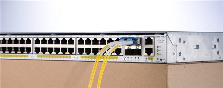
Cisco switch

What’s the Magic of White Box Switch?

The biggest difference between white box switch and traditional switch is the software of the white box switch is not dependent on its hardware. If you bought a white box switch from one provider, you can also use the software from another provider. This allows the customers to flexibly design and set their network and switches. This features makes the white box switches become very popular in SDN (Software Defined Network). Customers can program white box switches to create routing tables and route connections by the using of OpenFlow protocol or another south bound API in SDN environments.
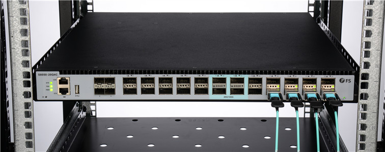
white box switch

In another aspect, the white box switch is usually much cheaper than the traditional switch, which makes it become popular for both large data center and smaller network. Most white box switch has high port density. Some large companies like Facebook, which need massive switches to be deployed in their data centers. The using of the high density white box switch would save a lot. They don’t need to depend on the traditional switch vendors. Meanwhile, they are able to customize their white box switches to meet the specific requirements for networking and business. The price and flexibility of the white box switches are also very attractive to some small network.

Some might get confused about the quality of the white box switch, because they are so cheap. Actually, the hardware of most switches is coming from the same company, what the customers pay for is usually the software and the logo of the traditional switch. The white box switch can also provide high performance.

Will White Box Switch Change the Future?

The white box switch can have as good or even better performance in SDN applications compared with traditional switch. However, it has great advantages on the cost, flexibility and applications. We don’t know how things will go in the future. But it is sure that white box switch will make some difference. According to the survey, more than 90% of the operators thought they will deploy the SDN in some point in the future, which means the white box switches are also being looking good in the future. Even some larger vendors are thinking about providing white box switches. It is sure that the white box switch is at its very early stage, but it is providing tremendous potential for our telecommunication network and many data centers or server rooms.

Conclusion

It is apparent that the traditional switch will still be an important role of the telecommunication network and data centers for a long time. However, benefits of the white box switch and SDN won’t be ignored. The fierce competition in white box switch market is also a great promoter. No matter how the future will go, it is worth trying for the deployment of the white box switch and SDN.

Resource: http://www.fs.com/blog/white-box-switch-or-traditional-switch.html

Cat5e Cable Structure and Cat5e Wiring Diagram

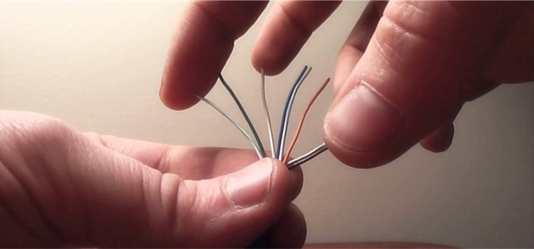
Network cables like Cat5, Cat5e and Cat6 are widely used in our network. Various Ethernet network cables are being invented. They can support different transmission distances and applications. Cat5e cables can support 1000base-T transmission up to 100 m, which meet the requirements of various applications in our home, office and data center. It has better performance than Cat5 and lower price than Cat6 making it a widely accepted type of Ethernet cable. This post introduces the details of Cat5e cable structure, Cat5e wiring, and wiring diagram.

Cat5e Wiring

Structure of Cat5e Cable

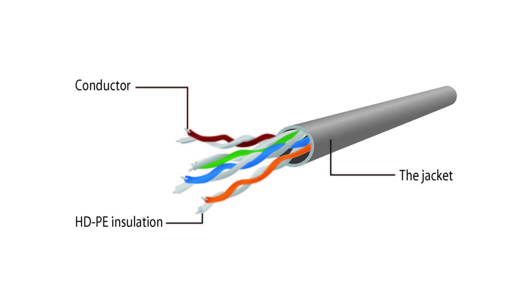
Cat5e uses four twisted pairs for transmission in each cable. The following picture shows the structure of the Cat5e cable. The termination of Cat5e Ethernet cable should use RJ45 connectors. As there are four pairs of copper wires inside a length of Cat5e cable, the cable pinouts should be carefully managed. For Cat5e, there are two commonly used methods for termination: straight-through and Crossover.

cat5e cable

Cat5e Wiring Diagram and Methods

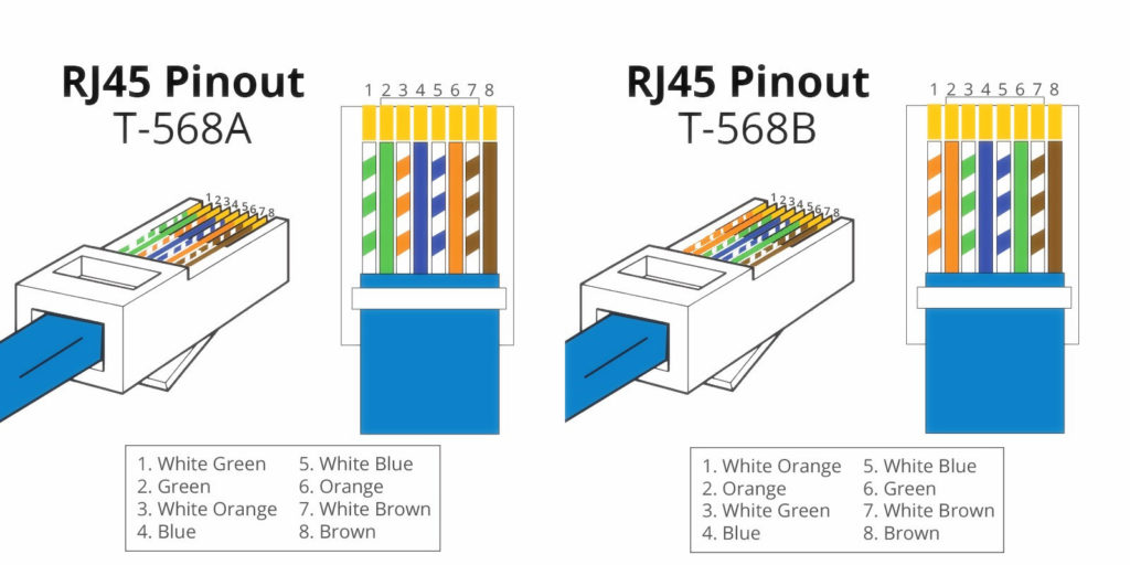
Each pair of copper wires in the Cat5e has insulation with a specific color for easier identification. Cat5e wiring should follow the standard color code.

For the straight-through wiring method, there are two standards recognized by ANSI, TIA and EIA: T568A and T568B. Both of them can be used. However, the T568B is considered better than T568A wiring standard. The following picture shows, the wiring diagram of the two standards.

straight through cat5e

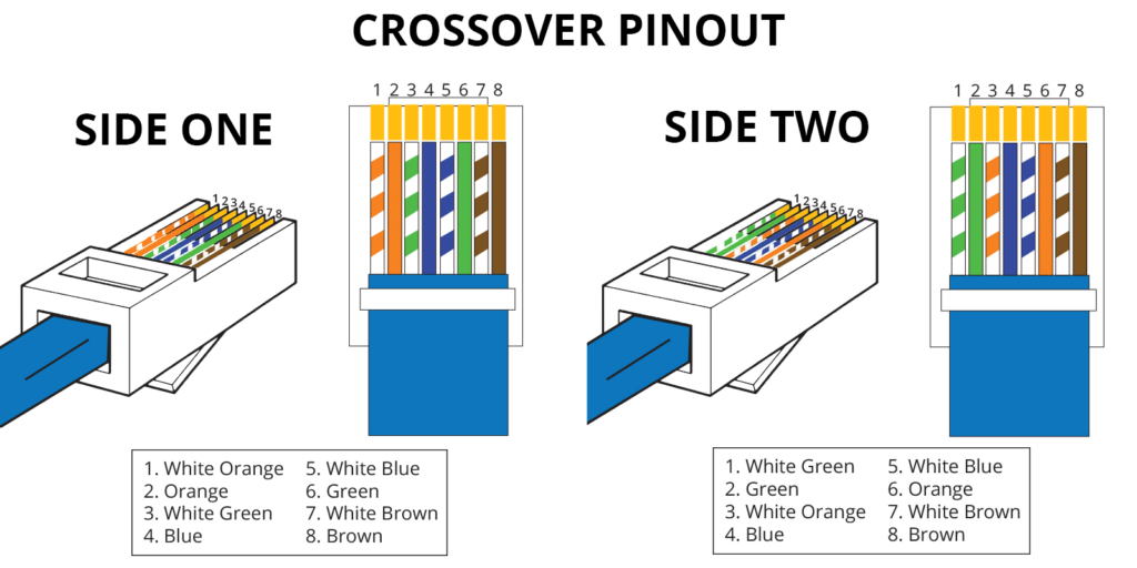
When you are doing the straight-through wiring, the cable pinout on the two ends of the Cat5e cable should be the same. However, for the crossover wiring method, the RJ45 pinouts on each end of the Cat5e are different. The following picture shows how the eight wires are used for transmission in a crossover terminated Cat5e cable.

Crossover cat5e

Actually, if you want to connect a T568A device with T568B device, you can use this crossover wiring method. The following picture shows the pinouts on each end of the Cat5e cable.

Crossover cat5e

How to Wire Cat5e Cables?

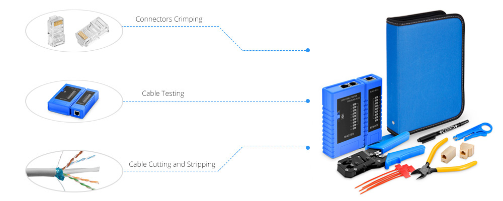
To terminate a Cat5e cable, you should prepare the cable. Here recommend a set of network installation tool kit which contains all you need to wire a category cable.

network installation tool kit

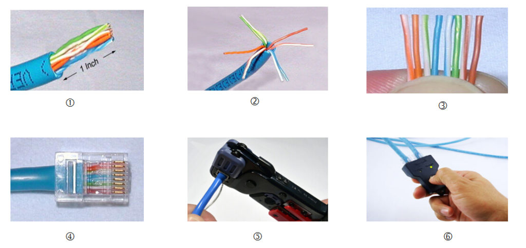
The following shows the process of how to terminate theEthernet cable:

cat5e wiring

Step 1, cut the cable to proper length and use the wire stripper to remove the outer jacket.

Step 2, untwist wires and trim the excess part. Flatten the wires out as much as possible, because they need to be very straight for proper insertion into the connector.

Step 3, hold the cable ends and place the wires in orders from left to right according to T568A or T568B wire scheme.

Step 4, insert the wires into the RJ45 connector. The wires must be sequenced in the same order of step 3.

Step 5, use the crimping tool to squeeze the plug. This ensures the firm connection between the cable and the plug.

Step 6, repeat the process on the opposite end and test the terminated cable to make sure communications between cable ends and the network is correct.

Cat5e Solution

The Cat5e has great advantages in various applications and there are many related products, like Cat5e patch cable, Cat5e bulk cable, Cat5e patch panel provided in the market. Kindly contact sales@fs.com for more details about Cat5e products, if you are interested.

Related Articles:
Quick View of Ethernet Cables Cat5, Cat5e And Cat6
Home Ethernet Wiring Guide: How to Get a Wired Home Network?
Patch Cable vs. Crossover Cable: What Is the Difference?

MTP Conversion Cable and Its Usage

12-fiber MTP and 24-fiber MTP cables are widely used in 40G and 100G high density cabling. However, in many cases, not all the fibers are used. For instance, to connect a 40G-SR4 QSFP+ module, we usually use a 12-fiber MTP cable with only 8 fibers in use. If you have built a 24-fiber cabling system, you can use MTP conversion cable to make full use of the existing optical fibers.

MTP conversion cable

MTP Conversion Cable

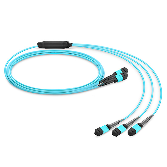
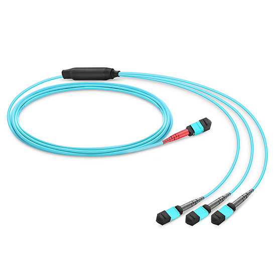
Unlike MTP-LC harness cable, MTP conversion cables are terminated with MTP connectors on both ends. However, the MTP connectors on each end are different in fiber counts and types. MTP conversion cable can provide more possibilities for the existing 24-fiber cabling system. The following are the most commonly used MTP conversion cable:

1*2 MTP conversion cable 2*3 MTP conversion cable 1*3 MTP conversion cable
1*2 MTP conversion cable 2*3 MTP conversion cable 1*3 MTP conversion cable
24-Fiber MTP to 2*12-Fiber MTP 2*12-Fiber MTP to 3*8-Fiber MTP 24-Fiber MTP to 3*8-Fiber MTP
MTP Conversion Cable Application

The total fiber counts of the above three MTP conversion cables are all 24. But the can provide different connections in multi-fiber cabling system. The following will introduce the applications of these cables.

1*2 MTP Conversion Cable

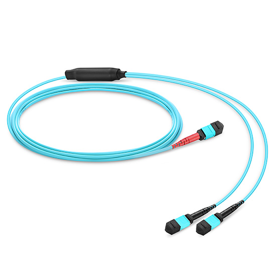
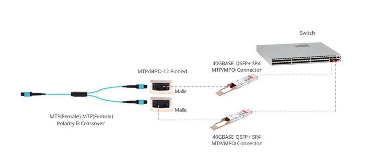
This MTP conversion cable has one end terminated with a 24-fiber MTP connector and the other end terminated with two 12-fiber MTP connector. With this cable, two 12-fiber optical singles can be transferred on to a 24-fiber cable for transmission. In multimode cabling system, the optical signals of two 40G-SR4 QSFP+ modules can be transmitted over a single 24-fiber MTP cable as shown in the following picture.

1*2 MTP conversion cable
1*3 MTP Conversion Cable

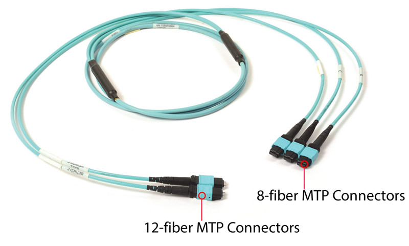
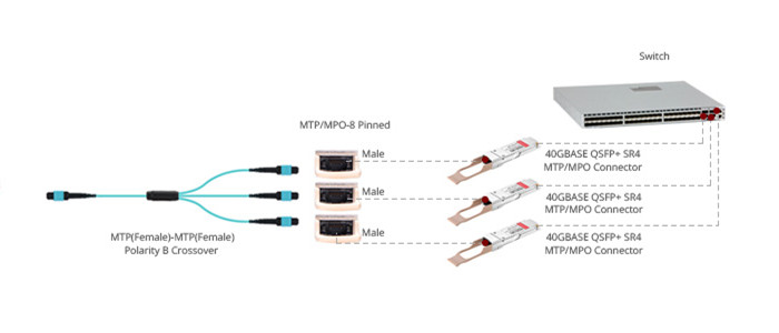
1*3 MTP conversion cable has one 24-fiber MTP connector terminated on one end and three 8-fiber MTP connector one the other end. The 8-fiber MTP connectors can be connected to 40G-SR4 QSFP+ modules. This MTP conversion cable utilizes 100% of the existing 24 optical fibers. Each fiber can be used to transmit 10G optical data. Three 40G dual-way transmissions can be achieved on the existing 24-fiber MTP cable. It can also be used to breakout the 120G CXP module signals into three 40G QSFP+ SR4 optical signals.

1*3 MTP conversion cable
2*3 MTP Conversion Cable

2*3 MTP conversion cable is terminated with two 12-fiber MTP connectors and three 8-fiber MTP connectors. This MTP conversion cable allows three 40G-SR4 optical signal transmit on the existing two 12-fiber MTP trunk cables as shown in the following. If you have built a 12-fiber MTP cabling system. This 2*3 MTP conversion cable can increase about 30% capacity of the existing network.

2*3 MTP conversion cable

MTP Conversion Cable Selection

MTP conversion cables are designed to provide a more flexible multi-fiber cabling system based on MTP products. It can largely increase the capacity of the existing 12-fiber and 24-fiber MTP network. The above mentioned MTP conversion cable in different fiber types and cable lengths. Kindly contact sales@fs.com for more details if you are interested.

Optical Line Protection System

Increasing the stability and reliability of the optical network is really important to our optical network. However, problems like optical fiber faults and line interruption are the largest risks that affect the communication and services that carried by optical fibers. To minimized the affection by these problems, optical line protection (OLP) systems are usually built in today’s optical networks, especially for backbone and important business line. Optical line protection uses principle of optical switch to build a backup path on vacant optical fiber. A simple optical line protection should contain a main path and a secondary path.

optical line protection

OLP 1:1 and OLP 1+1

There are different types of optical line protection devices for network protection. The most commonly used OLP are OLP 1:1 and OLP 1+1. Both of them require a spare fiber optic path. But they use different methods to secure the optical communication networks.

The following picture shows the transmission method of a fiber network deployed with OLP 1:1. The 1:1 optical line protection system uses a selective transmitting and selective receiving mode. There are a main route and a standby route between the two sites. The Tx port is connected to the optical switch inside the OLP device. When there is a fault on the main route, the Rx port will detect the decreasing of the optical power. Then, this OLP 1:1 system will switch the transmitting and receiving businesses from the main route to the standby route. 1:1 OLP system has low insertion loss and support the monitoring of the backup path. In this OLP system the optical fiber for backup path can be used for other business.

OLP 1:1

For OLP 1+1, things will be different as shown in the following picture. OLP 1+1 system chooses a mode of dual transmitting and selective receiving. In OLP 1+1, the optical power from Tx are splitted with a split ratio of 50:50 on the main route and the standby route, which means both the main and standby routes are in use no matter whether there is a fault in the main route. While for Rx, the optical signal with better quality will be selected. The advantage of OLP 1+1 system is fast switching and low cost. However, there will be larger insertion loss compared with OLP 1:1 system. This OLP 1+1 system is suggested to be used with short-distance optical lines with large surplus.

OLP 1+1

OBP (Optical Bypass Protection)

The OLP 1+1 and OLP 1:1 are used to ensure the optical transmission when there are faults in optical fibers. However, some problems of the optical networks are caused by devices that are deployed in the optical network, which will affect the transmission in the whole link. To increase the stability in this situation, optical bypass protection devices are deployed in the network. The following picture shows how the bypass protection device protect the optical line from normal to barrier situation. When there is no optical signal of the device or power down occurs, it will automatically bypass the device, so as to ensure the normal communication.

optical bypass protection

OLP and OBP Solution

The OLP and OBP systems are both economical solutions to secure our optical network. There are mainly two designs of these devices—plug-in card version and standalone version. The following listed several OLP and OBP for your references.

ID Product Description
66007 Optical Line Protection (OLP) 1:1, 1U Rack Mount
66008 Optical Line Protection (OLP) 1+1, 1U Rack Mount
66009 Optical Line Protection (OLP) 1:1, Plug-in Card Type
66010 Optical Line Protection (OLP) 1+1, Plug-in Card Type
66011 Optical Bypass Protection (OBP), 1U Rack Mount
66012 Optical Bypass Protection (OBP), Plug-in Card Type

OEO 3R Converter Instruction

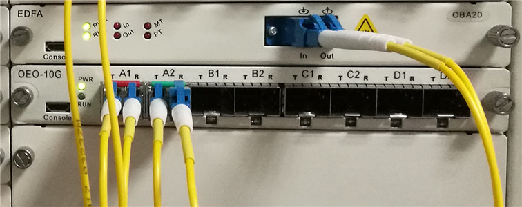
Optical signals are transmitted on specific wavelengths like 850nm, 1310nm, 1550nm and CWDM wavelengths and DWDM wavelengths. In some cases, it occurs that you need to converter a wavelength of optical signals into another wavelength for transmission. A useful component OEO 3R converter is suggested to be used. The OEO converter is also known as transponder OEO. This component uses the Optical-Electrical-Optical principle to offer the conversion between different wavelengths of optical signals. “3R” means re-timing, re-shaping, and re-amplifying.

OEO 3R

OEO 3R Converter for Wavelength Conversion

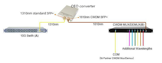
OEO 3R converter can fit various applications and can be installed in the network flexibly. It is a very popular component in DWDM and CWDM networks. In many situations, we are using fiber optic transceiver that working on 850nm, 1310nm and 1550nm for optical signal transmission. However, if you want to add optical signals of these wavelengths into a CWDM or DWDM network, you should firstly convert the wavelengths into CWDM or DWDM wavelengths. With OEO converter, this could be easy. The following picture shows a case which uses OEO converter in a CWDM network for wavelengths conversion.

OEO WDM

In this case, a 10G SFP+ to SFP+ OEO with two SFP+ ports, is being used for wavelength conversion between 1310nm and CWDM wavelength 1610nm. A 10G-LR SFP+ module working on 1310nm is used in a 10G switch on site A. To add the optical signal of this port in to the existing CWDM network, this module is being connected to another 10G LR SFP+ module which is being inserted in the SFP+ Port 1 of the OEO converter. A CWDM 1610nm SFP+ module, connected to the CWDM MUX/DEMUX on site B, is being used in the other port of this OEO converter. The OEO converter the 1310nm signal into 1610nm CWDM signal. The optical signal from site A is being added into the CWDM network via the CWDM MUX/DEMUX on site B.

OEO 3R Converter for Fiber Mode Conversion and Fiber Repeating

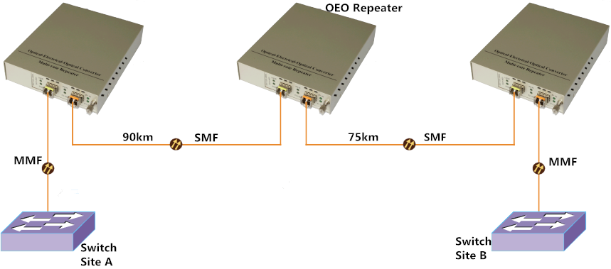
The using of OEO converter for wavelength conversion is simple. As above mentioned, the OEO 3R converter has the function of re-timing, re-shaping, and re-amplifying, the OEO 3R converter can also be used as fiber mode converter and fiber repeater converters. The following picture shows another case with OEO 3R converter working as fiber repeater and providing conversion between single-mode and multimode.

OEO 3R

In this case, three SFP+ to SFP+ OEO converters are deployed between Site A and Site B for long distance dual-way optical transmission. The optical signal from Site A is firstly converted from multi-mode fiber into single-mode fiber for 90km transmission by one OEO converter. Then, a second OEO converter is used as a repeater to “3R” the optical signals. After that, the single-mode signal will travel another 75km. Before the signal reaches the switch in Site B, another OEO converter converts the single-mode signal into multimode signal.

OEO Converter Options

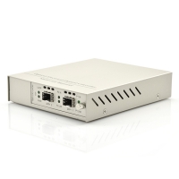
OEO converters provide flexible solution for optical transmission network. Except the above mentioned 10G SFP+ to SFP+ OEO converter, there are many other OEO converters with different port types, port counts and designs. The following table listed several OEO converters for your reference.

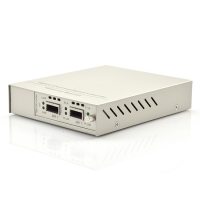
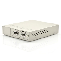
 SFP+ to SFP+ OEO  XFP OEO
SFP+ to SFP+ OEO Converter XFP to XFP OEO Converter
 QSFP+ OEO  8 SFP+ OEO
QSFP+ to QSFP+ OEO Converter 8 Ports SFP+ 10G OEO Converter