400G Multimode Fiber: 400G SR4.2 vs 400G SR8

Cloud and AI applications are driving demand for data rates beyond 100 Gb/s, moving to high-speed and low-power 400 Gb/s interconnects. The optical fiber industry is responding by developing two IEEE 400G Ethernet standards, namely 400GBASE-SR4.2 and 400GBASE-SR8, to support the short-reach application space inside the data center. This article will elaborate on the two standards and their comparison.

400GBASE-SR4.2

400GBASE-SR4.2, also called 400GBASE-BD4.2, is a 4-pair, 2-wavelength multimode solution that supports reaches of 70m (OM3), 100m (OM4), and 150m (OM5). It is not only the first instance of an IEEE 802.3 solution that employs both multiple pairs of fibers and multiple wavelengths, but also the first Ethernet standard to use two short wavelengths to double multimode fiber capacity from 50 Gb/s to 100 Gb/s per fiber.

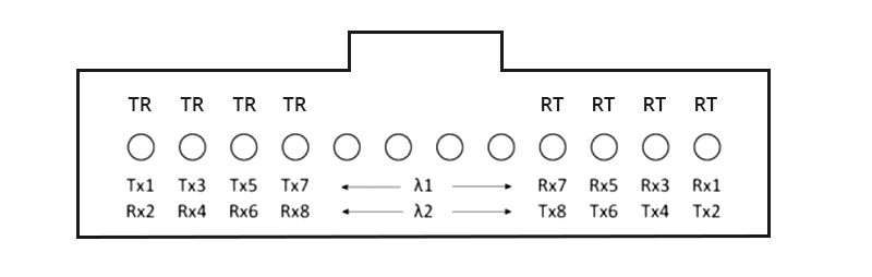
400GBASE-SR4.2 operates over the same type of cabling used to support 40GBASE-SR4, 100GBASE-SR4 and 200GBASE-SR4. It uses bidirectional transmission on each fiber, with each wavelength traveling in opposite directions. As such, each active position at the transceiver is both a transmitter and a receiver, which means 400GBASE-SR4.2 has eight optical transmitters and eight optical receivers in a bidirectional optical configuration.

The optical lane arrangement is shown as follows. The leftmost four positions labeled TR transmit wavelength λ1 (850nm) and receive wavelength λ2 (910nm). Conversely, the rightmost four positions labeled RT receive wavelength λ1 and transmit wavelength λ2.
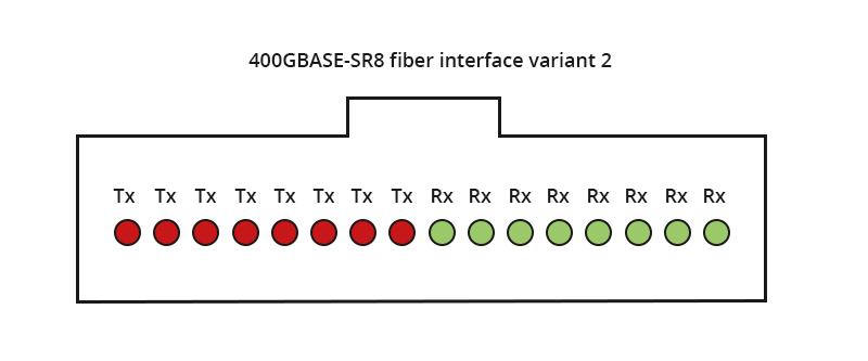
400GBASE-SR4.2 fiber interface

400GBASE-SR8

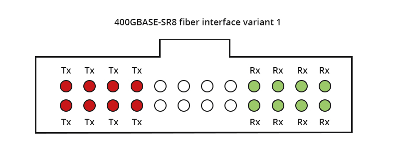
400GBASE-SR8 is an 8-pair, 1-wavelength multimode solution that supports reaches of 70m (OM3), 100m (OM4 & OM5). It is the first IEEE fiber interface to use eight pairs of fibers. Unlike 400GBASE-SR4.2, it operates over a single wavelength (850nm) with each pair supporting 50 Gb/s transmission. In addition, it has two variants of optical lane arrangement. One variant uses the 24-fiber MPO, configured as two rows of 12 fibers, and the other interface variant uses a single-row MPO-16.

400GBASE-SR8 fiber interface variant 1
400GBASE-SR8 fiber interface variant 2

400GBASE-SR8 offers flexibility of fiber shuffling with 50G/100G/200G configurations. It also supports breakout at different speeds for various applications such as compute, storage, flash, GPU, and TPU. 400G-SR8 QSFP DD/OSFP transceivers can be used as 400GBASE-SR8, 2x200GBASE-SR4, 4x100GBASE-SR2, 8x50GBASE-SR.

400G SR4.2 vs. 400G SR8

As multimode solutions for 400G Ethernet, 400GBASE-SR4.2 and 400GBASE-SR8 share some features, but they also differ in a number of ways as discussed in the previous section.

The following table shows a clear picture of how they compare to each other.

 400GBASE-SR4.2400GBASE-SR8
AllianceIEEE 802.3cmIEEE 802.3cm (breakout: 802.3cd)
Max reach150m over OM5100m over OM4/OM5
Fibers8 fibers16 fibers (ribbon patch cord)
Wavelength2 wavelengths (850nm and 910nm)1 wavelength (850nm)
BiDi technologySupport/
Signal modulation formatPAM4 signalingPAM4 signaling
LaserVCSELVCSEL
Form factorQSFP-DD, OSFPQSFP-DD, OSFP

400GBASE-SR8 is technically simple but requires a ribbon patch cord with 16 fibers. It is usually built with 8 VCSEL lasers and doesn’t include any gearbox, so the overall cost of modules and fibers remains low. By contrast, 400GBASE-SR4.2 is technically more complex so the overall cost of related fibers or modules is higher, but it can support a longer reach.

In addition, 400GBASE-SR8 offers both flexibility and higher density. It supports fiber shuffling with 50G/100G/200G configurations and fanout at different I/O speeds for various applications. A 400G-SR8 QSFP-DD transceiver can be used as 400GBASE-SR8, 2x200GBASE-SR4, 4x100GBASE-SR2, or 8x50GBASE-SR.

400G SR4.2 & 400G SR8: Boosting Higher Speed Ethernet

As multimode fiber continues to evolve to serve growing demands for speed and capacity, both 400GBASE-SR4.2 and 400GBASE-SR8 help boost 400G Ethernet and scale up multimode fiber links too ensure the viability of optical solutions for various demanding applications.

The two IEEE 802.3cm standards provide a smooth evolution path for Ethernet, boosting cloud-based services and applications. Future advances point toward the ability to support even higher data rates as they are upgraded to the next level. The data center Industry will take advantage of the latest multimode fiber technology such as OM5 fiber, and use multiple wavelengths to transmit 100 Gb/s and 400 Gb/s over fibers over short reach of more than150 meters.

Beyond 2021-2022 timeframe, once an 800 Gb/s Ethernet standard is standardized, using more advanced technology with two-wavelength operation could create an 800 Gb/s, four-pair link. At the same time a single wavelength could support an 800 Gb/s eight-pair link. In this sense, 400GBASE-SR4.2 and 400GBASE-SR8 are setting the pace for a promising future.

Article Source: 400G Multimode Fiber: 400G SR4.2 vs 400G SR8

Related Articles:

400G Modules: Comparing 400GBASE-LR8 and 400GBASE-LR4
400G Optics in Hyperscale Data Centers
How 400G Has Transformed Data Centers

Importance of FEC for 400G

The rapid adoption of 400G technologies has seen a spike in bandwidth demands and a low tolerance for errors and latency in data transmission. Data centers are now rethinking the design of data communication systems to expand the available bandwidth while improving transmission quality.

Meeting this goal can be quite challenging, considering that improving one aspect of data transmission consequently hurts another. However, one solution seems to stand out from the rest as far as enabling reliable, efficient, and high-quality data transmission is concerned. We’ve discussed more on Forward Error Correction (FEC) and 400G technology in the sections below, including the FEC considerations for 400Gbps Ethernet.

What Is FEC?

Forward Error Correction is an error rectification method used in digital signals to improve data reliability. The technique is used to detect and correct errors in data being transmitted without retransmitting the data.

FEC introduces redundant data and the error-correcting code before data transmission is done. The redundant bits/data are complex functions of the original information and are sent multiple times since an error can appear in any transmitted samples. The receiver then corrects errors without requesting retransmission of the data by acknowledging only parts of the data with no apparent errors.

FEC codes can also generate bit-error-rate signals used as feedback to fine-tune analog receiving electronics. The FEC code design determines the number of missing bits that can be corrected. Block codes and convolutional codes are the two FEC code categories that are widely used. Convolutional codes handle arbitrary-length data and use the Viterbi algorithm for decoding purposes. On the other hand, block codes handle fixed-size data packets, and partial code blocks are decoded in polynomial time to the code block length.

FEC

What Is 400G?

This is the next generation of cloud infrastructure widely used by high-traffic volume data centers, telecommunication service providers, and other large enterprises with relentless data transmission needs. The rapidly increasing network traffic has seen network carriers continually face bandwidth challenges. This exponential sprout in traffic is driven by the increased deployments of machine learning, cloud computing, artificial intelligence (AI), and IoT devices.

Compared to the previous 100G solution, 400G, also known as 400GbE or 400GB/s, is four times faster. This Terabit Ethernet transmits data at 400 billion bits per second, i.e., in optical wavelength; hence it’s finding application in high-speed, high-performance deployments.

The 400G technology also delivers the power, data density, and efficiency required for cutting-edge technologies such as virtual reality (VR), augmented reality (AR), 5G, and 4K video streaming. Besides consuming less power, the speeds also support scale-out and scale-up architectures by providing high density, low-cost-per-bit, and reliable throughput.

Why 400G Requires FEC

Several data centers are adopting 400 Gigabit Ethernet, thanks to the faster network speeds and expanded use cases that allow for new business opportunities. This 400GE data transmission standard uses the PAM4 technology, which offers twice the transmission speed of NRZ technology used for 100GE.

The increased speed and convenience of PAM4 also come with its own challenges. For instance, the PAM4 transmission speed is twice as fast as that of NRZ, but the signal levels are half that of 100G technology. This degrades the signal-to-noise ratio (SNR); hence 400G transmissions are more susceptible to distortion.

Therefore, forward error correction (FEC) is used to solve the waveform distortion challenge common with 400GE transmission. That said, the actual transmission rate of a 400G Ethernet link is 425Gbps, with the additional 25 bits used in establishing the FEC techniques. 400GE elements, such as DR4 and FR4 optics, have transmission errors, which FEC helps rectify.

FEC Considerations for 400Gbps Ethernet

With the 802.3bj standards, FEC-related latency is often targeted to be equal to or less than 100ns. Here, the receive time for FEC-frame takes approximately 50ns, with the rest time budget used for decoding. This FEC latency target is practical and achievable.

Using similar/same FEC code for the 400GbE transmission makes it possible to achieve lower latency. But when a higher coding gain FEC is required, e.g., at the PMD level, one can trade off FEC latency for the desired coding gain. It’s therefore recommended to keep a similar latency target (preferably 100ns) while pushing for a higher coding gain of FEC.

Given that PAM4 modulation is used, FEC’s target coding gain (CG) could be over 8dB. And since soft-decision FEC comes with excessive power consumption, it’s not often preferred for 400GE deployments. Similarly, conventional block codes with their limited latency need a higher overclocking ratio to achieve the target.

Assuming that a transcoding scheme similar to that used in 802.3bj is included, the overclocking ratio should be less than 10%. This helps minimize the line rate increase while ensuring sufficient coding gain with limited latency.

So under 100ns latency and less than 10% overclocking ratio, FEC codes with about 8.5dB coding gain are realizable for 400GE transmission. Similarly, you can employ M (i.e., M>1) independent encoders for M-interleaved block codes instead of using parallel encoders to achieve 400G throughput.

Conclusion

400GE transmission offers several benefits to data centers and large enterprises that rely on high-speed data transmission for efficient operation. And while this 400G technology is highly reliable, it introduces some transmission errors that can be solved effectively using forward error correction techniques. There are also some FEC considerations for 400G Ethernet, most of which rely on your unique data transmission and network needs.

Article Source: Importance of FEC for 400G

Related Articles:
How 400G Ethernet Influences Enterprise Networks?
How Is 5G Pushing the 400G Network Transformation?
400G Transceiver, DAC, or AOC: How to Choose?

FAQs About FS 400G Transceivers

FS 400G transceivers offer customers a wide variety of super high-density 400 Gigabit Ethernet connectivity options for data centers, enterprise networks, and service provider applications. Here is a list of FAQs about our new generation of 400G transceiver modules.

Q: What 400G transceivers are available from FS?

A: FS supports a full range of 400G optical transceivers in both OSFP and QSFP-DD form factors, 400G AOCs and DACs, and 400G breakout cables. The tables below summarize the 400G connectivity options FS supports.

CategoryProductMax Cable DistanceConnectorMediaPower Consumption
400G Transceivers400G QSFP-DD SR870m@OM3/100m@OM4MTP/MPO-16 (APC)MMF≤10W
400G QSFP-DD DR4500mMTP/MPO-12 (APC)SMF≤10W
400G QSFP-DD XDR42kmMTP/MPO-12SMF≤12W
400G QSFP-DD FR42kmDuplex LCSMF≤12W
400G QSFP-DD LR410kmDuplex LCSMF≤12W
400G QSFP-DD PLR410kmMTP/MPO-12SMF≤10W
400G QSFP-DD LR810kmDuplex LCSMF≤14W
400G QSFP-DD ER840kmDuplex LCSMF≤14W
400G OSFP SR8100mMTP/MPO-16MMF≤12W
400G OSFP DR4500mMTP/MPO-12 (APC)SMF≤10W
400G Cables400G QSFP-DD DAC/AOC100mQSFP-DD/≤11W
400G Breakout DAC/AOC30mQSFP-DD to 2x QSFP56, QSFP-DD to 4x QSFP56, QSFP-DD to 4x QSFP28, QSFP-DD to 8x SFP56/≤11W

Q: What are the benefits that FS 400G transceivers can offer?

A: FS 400G transceivers help cloud operators, service providers, and enterprises to achieve higher bandwidth at lower cost and power per gigabit. Key benefits of FS 400G transceivers include:

  • With both OSFP and QSFP-DD form factors to meet your diverse needs of ramping up to 400G transmission.
  • SiPh-based technology used on some FS 400G transceivers for lower power & cost and higher density.
  • Compliant with QSFP-DD MSA and IEEE 802.3bs, and tested in host devices for proven interoperability, superior performance, quality, and reliability.
  • Compatible with mainstream brands such as Cisco, Juniper, Arista, Dell, Mellanox, etc.
  • Simplify your network by reducing the number of optical fiber links, connectors and patch panels by a factor of 4.

Q: What are the application scenarios of FS 400G transceivers?

A: 400G QSFP-DD transceiver modules are the backbone of high-performance 400G networks. FS 400G transceivers can be used in various scenarios. Generally speaking, it depends on the connection distance you want to cover. For example, you can use 400G DAC and AOC cables for short-reach connections between ToR switch and server. For 2km to 10km data center interconnection connections, QSFP-DD FR4 or LR4 modules are better high-quality and economical choices.

Q: What quality certifications do you have for your 400G transceivers?

A: FS 400G transceivers accord with a range of certifications for optical transceivers including ISO 9001:2015, RoHS, REACH, CB, RCM, FCC, and Russian TR CU certificate (EAC Certificate). Rest assured that our products will meet essential quality and safety requirements.

Q: Are FS 400G transceivers compatible with Cisco or Juniper brands?

A: Many of our 400G transceiver modules are compatible with Cisco, Juniper, Arista, Dell, Mellanox, etc. You can always ask for a compatibility test before the purchase to check whether our transceiver is compatible with your devices. If you’re deploying a larger network or upgrading your current data center architecture, compatible transceiver modules may come in handy as they can be immediately installed without compatibility problems and fit right into your data center infrastructure.

Q: Can I plug FS OSFP module into a 400G QSFP-DD port, or FS QSFP-DD module into an OSFP port?

A: No. OSFP and QSFP-DD are two physically distinct form factors. If you have an OSFP system, then FS 400G OSFP modules must be used. If you have a QSFP-DD system, then FS 400G QSFP-DD modules must be used.

Q: Can FS 100G QSFP module be plugged into a 400G QSFP-DD port?

A: Yes. A 40/100GQSFP transceiver module can be inserted into a QSFP-DD port as QSFP-DD is backward compatible with QSFP, QSFP+, and QSFP28 transceiver modules. When using a QSFP module in a 400G QSFP-DD port, the QSFP-DD port must be configured for a data rate of 100G.

Q: What should I do if I don’t know which transceiver module is the right one for me?

A: Our dedicated customer support offers 24/7 technical assistance. If you have any questions about our transceiver modules, such as how to select the right 400G optical transceiver for your switches, how to choose between different form factors, what to do when typical technical glitches occur, or how to place an order, don’t hesitate to contact our tech support.

Q: Can I return the product or get a refund?

A: FS wants you to be thrilled with our 400G transceiver modules. However, if you need to return an item or ask to get a refund, we’re here to help. For all 400G transceiver modules, DAC & AOC cables, and breakout cables, you have 30 calendar days to return an item from the date you received it, which means the request must be submitted within the return/exchange window. Refunds will be processed after FS receives and inspects the returned items.

Q: How long is the warranty period for FS 400G transceivers?

A: We offer you a warranty period of five years for the purchase of 400G transceiver modules, DAC & AOC cables, and breakout cables. The warranty covers only defects arising under normal use and does not include malfunctions or failures resulting from misuse, abuse, neglect, alteration, problems with electrical power, usage not in accordance with product instructions, acts of nature, or improper installation or improper operation or repairs made by anyone other than FS or an FS authorized service provider. Please check FS Products Warranty for detailed info.

If you have any questions about FS 400G transceiver modules, you can always Contact Us for assistance.

Article Source

https://community.fs.com/news/faqs-about-fs-400g-transceivers.html

Related Articles

FAQs on 400G Transceivers and Cables

How Many 400G Transceiver Types Are in the Market?

Basics about 400G DAC and 400G AOC

Data centers, enterprises, and high-performance computing environments require flexible and well-defined 50G, 100G, 200G, and 400G direct attach cables for interconnection within a rack or between adjacent racks. With the development of 400G technology, 400G direct attach cables for short-distance DCI (Data Center Interconnect) have been mass-produced and put into market, which includes 400G DAC and 400G AOC.

Main Types of 400G DAC & AOC in the Market

Either 400G DAC or 400G AOC comes with two main form factors: QSFP-DD and OSFP, both of which can carry 8x50Gb/s PAM4 electrical lanes. Besides, there are also 400G breakout DAC/AOCs, with one 400G connector at one end, and several same connectors whose total rate is 400G at the other end. The table below shows the main types of 400G DAC /AOC and the 400G breakout DAC/AOCs in the market.

CatagoryNameProduct DescriptionReachApplication
400G QSFP-DD DACQSFP-DD to QSFP-DD DACwith each 400G QSFP-DD using 8x 50G PAM4 electrical lanesno more than 3m400G network direct connection
400G QSFP-DD Breakout DACQSFP-DD to 2x 200G QSFP56 DACwith each 200G QSFP56 using 4x 50G PAM4 electrical lanesno more than 3m400G to 200G network connection
QSFP-DD to 4x 100G QSFPs DACwith each 100G QSFPs using 2x 50G PAM4 electrical lanesno more than 3m400G to 100G network connection
QSFP-DD to 8x 50G SFP56 DACwith each 50G SFP56 using 1x 50G PAM4 electrical laneno more than 3m400G to 50G network connection
400G QSFP-DD AOCQSFP-DD to QSFP-DD AOCwith each 400G QSFP-DD using 8x 50G PAM4 electrical lanes70m (OM3) or 100m (OM4)400G network direct connection
400G QSFP-DD Breakout AOCQSFP-DD to 2x 200G QSFP56 AOCwith each 200G QSFP56 using 4X 50G PAM4 electrical lane70m (OM3) or 100m (OM4)400G to 200G network connection
QSFP-DD to 8x 50G SFP56 AOCwith each 50G SFP56 using 1x 50G PAM4 electrical lane70m (OM3) or 100m (OM4)400G to 50G network connection
400G OSFP DACOSFP to OSFP DACwith each 400G OSFP using 8x 50G PAM4 electrical lanesno more than 3m400G network direct connection
400G OSFP Breakout DACOSFP to 2x 200G QSFP56 DACwith each 200G QSFP56 using 4x 50G PAM4 electrical lanesno more than 3m400G to 200G network connection
OSFP to 4x100G QSFPs DACwith each 100G QSFPs using 2x 50G PAM4 electrical lanesno more than 3m400G to 100G network connection
OSFP to 8x 50G SFP56 DACwith each 50G SFP56 using 1x 50G PAM4 electrical laneno more than 3m400G to 50G network connection
400G OSFP AOCOSFP to OSFP AOCwith each 400G OSFP using 8x 50G PAM4 electrical lanes70m (OM3) or 100m (OM4)400G network direct connection

Differences Between 400G DAC and 400G AOC

According to the table, we know that the main differences between 400G DAC and 400G AOC are transmission distance and the available types on the market. At present, 400G DAC can provide more breakout cables and better satisfy your different connection requirements. Apart from that, 400G DAC and AOC differ from each other in the following aspects.

  • Weight and volume – With fiber optic cable as transmission media, 400G AOC has about half the volume and only a quarter the weight of 400G copper DAC. Also, its cable bending radius is smaller than 400G DAC.
  • Interference-resistance – Since 400G AOC with fiber optic cable doesn’t conduct electrical currents, it is resistant to interference from electromagnetic, lightning, or radio signals during data transmission. While 400G DAC with copper cable is vulnerable to power lines, lightning, and signal-scrambling.
  • Price – On today’s 400GbE cable market, the price of the 400G AOC is often higher than that of 400G DAC, of course, with the same level. If both of them can meet your needs, you can choose a 400G DAC to save costs.

Further Consideration about 400G DAC and 400G AOC

Both 400G DAC and AOC are cost-effective solutions for short-distance transmission. When it comes to the transmission over 100m, 400G optical transceivers combined with the matched fiber optic cables are a suitable solution. In today’s market, 400G QSFP-DD/OSFP transceivers are continuously being pushed to the market and gradually realize mass production. So, what are 400G QSFP-DD/OSFP transceiver types and what fiber optic cables could be used with these 400G optical modules? Continue reading to find the answers in the two articles: 400G OSFP Transceiver Types Overview400G QSFP-DD Transceiver Types Overview.

FAQ about 400G DAC/AOC

Q: Why does 400G DAC/AOC adopt PAM4 modulation?

A: PAM4 is a more efficient modulation technology that can effectively improve the bandwidth utilization efficiency. With same Baud rate, PAM4 signal can transmit twice faster than the traditional NRZ signal. Also, the transmission costs are greatly reduced.

Q: What’s the key technology of 400G DAC/AOC?

A: The core technologies of 400G DAC/AOC are PAM4 and DSP. Since PAM4 is more sensitive to noise than NRZ especially in 400G AOC, DSP is introduced to make up for the disadvantage of PAM4. As a high-speed digital processing chip, DSP not only owns the function of recovering signal provided by the traditional CDR but also can make dispersion compensation and remove noise, nonlinear disturbance as well as other interferences.

FS 400G DAC Cables
Article Source

https://community.fs.com/blog/400g-direct-attach-cables-dac-and-aoc-overview.html

Related Articles

https://community.fs.com/blog/400g-transceiver-dac-or-aoc-how-to-choose.html

https://community.fs.com/news/fs-400g-cabling-solutions-dac-aoc-and-fiber-cabling.html

ROADM for 400G WDM Transmission

As global optical networks advance, there is an increasing necessity for new technologies such as 400G that meet the demands of network operators. Video streaming, surging data volumes, 5G network, remote working, and ever-growing business necessities create extreme bandwidth demands.

Network operators and data centers are also embracing WDM transmission to boost data transfer speed, increase bandwidth and enhance a better user experience. And to solve some of the common 400G WDM transmission problems, such as reduced transmission reach, ROADMs are being deployed. Below, we have discussed more about ROADM for 400G WDM transmission.

Reconfigurable Optical Add-drop Multiplexer (ROADM) Technology

ROADM is a device with access to all wavelengths on a fiber line. Introduced in the early 2000s, ROADM allows for remote configuration/reconfiguration of A-Z lightpaths. Its networking standard makes it possible to block, add, redirect or pass visible light beams and modulated infrared (IR) in the fiber-optic network depending on the particular wavelength.

ROADMs are employed in systems that utilize wavelength division multiplexing (WDM). It also supports more than two directions at sites for optical mesh-based networking. Unlike its predecessor, the OADM, ROADM can adjust the add/drop vs. pass-through configuration whenever traffic patterns change.

As a result, the operations are simplified by automating the connections through an intermediate site. This implies that it’s unnecessary to deploy technicians to perform manual patches in response to a new wavelength or alter a wavelength’s path. The results are optimized network traffic where bandwidth demands are met without incurring extra costs.

ROADM

Overview of Open ROADM

Open ROADM is a 400G pluggable solution that champions cross-vendor interoperability for optical equipment, including ROADMs, transponders, and pluggable optics. This solution defines some optical interoperability requirements for ROADM and comprises hardware devices that manage and routes traffic over the fiber optic lines.

Initially, Open ROADM was designed to address the rise in data traffic on wireless networks experienced between 2007 and 2015. The major components of Open ROADM – ROADM switch, pluggable optics, and transponder – are controllable via an open standards-based API accessible through an SDN Controller.

One of the main objectives of Open ROADM is to ensure network operators and vendors devise a universal approach to designing networks that are flexible, scalable, and cost-effective. It also offers a standard model to streamline the management of multi-vendor optical network infrastructure.

400G and WDM Transmission

WDM transmission is a multiplexing technique of several optical carrier signals through a single optical fiber channel by varying the wavelength of the laser lights. This technology allows different data streams to travel in both directions over a fiber network, increasing bandwidth and reducing the number of fibers used in the primary network or transmission line.

With 400G technology seeing widespread adoption in various industries, there’s a need for optical fiber networking systems to adapt and support the increasing data speeds and capacity. WDM transmission technique offers this convenience and is considered a technology of choice for transmitting larger amounts of data across networks/sites. WDM-based networks can also hold various data traffic at different speeds over an optical channel, allowing for increased flexibility.

400G WDM still faces a number of challenges. For instance, the high symbol rate stresses the DAC/ADC in terms of bandwidth, while the high-order quadrature amplitude modulation (QAM) stresses the DAC/ADC in terms of its ENOB (effective number of bits.)

As far as transmission performance is concerned, the high-order QAM requires more optical signal-to-noise ratio (OSNR) at the receiver side, which reduces the transmission reach. Additionally, it’s more sensitive to the accumulation of linear and non-linear phase noise. Most of these constraints can be solved with the use of ROADM architectures. We’ve discussed more below.

WDM Transmission

Open ROADM MSA and the ROADM Architecture for 400G WDM

The Open ROADM MSA defines some interoperability specifications for ROADM switches, pluggable optics, and transponders. Most ROADMs in the market are proprietary devices built by specific suppliers making interoperability a bit challenging. The Open ROADM MSA, therefore, seeks to provide the technical foundation to deploy networks with increased flexibility.

In other words, Open ROADM aims at disaggregating the data network by allowing for the coexistence of multiple transponders and ROADM vendors with a few restrictions. This can be quite helpful for 400G WDM systems, especially when lead-time and inventory issues arise, as the ability to mix & match can help eliminate delays.

By leveraging WDM for fiber gain as well as optical line systems with ROADMs, network operators can design virtual fiber paths between two points over some complex fiber topologies. That is, ROADMs introduce a logical transport underlay of single-hop router connections that can be optimized to suit the IP traffic topology. These aspects play a critical role in enhancing 400G adoption that offers the much-needed capacity-reach, flexibility, and efficiency for network operators.

That said, ROADMs have evolved over the years to support flexile-grid WSS technology. One of the basic ROADM architectures uses fixed filters for add/drop, while the other architectures offer flexibility in wavelength assignment/color or the option to freely route wavelengths in any direction with little to no restriction. This means you can implement multi-degree networking with multiple fiber paths for every node connecting to different sites. The benefit is that you can move traffic along another path if one fiber path isn’t working.

Conclusion

As data centers and network operators work on minimizing overall IP-optical network cost, there’s a push to implement robust, flexible, and optimized IP topologies. So by utilizing 400GbE client interfaces, ROADMs for 400G can satisfy the ever-growing volume requirements of DCI and cloud operators. Similarly, deploying pluggable modules and tapping into the WDM transmission technique increases network capacity and significantly reduces power consumption while simplifying maintenance and support.

Article Source: ROADM for 400G WDM Transmission
Related Articles:

400G ZR vs. Open ROADM vs. ZR+
FS 200G/400G CFP2-DCO Transceivers Overview

FS 400G Product Family Introduction