Tag Archives: data center

What Is Software-Defined Networking (SDN)?

SDN, short for Software-Defined Networking, is a networking architecture that separates the control plane from the data plane. It involves decoupling network intelligence and policies from the underlying network infrastructure, providing a centralized management and control framework.

How does Software-Defined Networking (SDN) Work?

SDN operates by employing a centralized controller that manages and configures network devices, such as switches and routers, through open protocols like OpenFlow. This controller acts as the brain of the network, allowing administrators to define network behavior and policies centrally, which are then enforced across the entire network infrastructure.SDN network can be classified into three layers, each of which consists of various components.

  • Application layer: The application layer contains network applications or functions that organizations use. There can be several applications related to network monitoring, network troubleshooting, network policies and security.
  • Control layer: The control layer is the mid layer that connects the infrastructure layer and the application layer. It means the centralized SDN controller software and serves as the land of control plane where intelligent logic is connected to the application plane.
  • Infrastructure layer: The infrastructure layer consists of various networking equipment, for instance, network switches, servers or gateways, which form the underlying network to forward network traffic to their destinations.

To communicate between the three layers of SDN network, northbound and southbound application programming interfaces (APIs) are used. Northbound API enables communications between the application layers and the controller, while southbound API allows the controller communicate with the networking equipment.

What are the Different Models of SDN?

Depending on how the controller layer is connected to SDN devices, SDN networks can be divided into four different types which we can classify as follows:

  1. Open SDN

Open SDN has a centralized control plane and uses OpenFlow for the southbound API of the traffic from physical or virtual switches to the SDN controller.

  1. API SDN

API SDN, is different from open SDN. Rather than relying on an open protocol, application programming interfaces control how data moves through the network on each device.

  1. Overlay Model SDN

Overlay model SDN doesn’t address physical netwroks underneath but builds a virtual network on top of the current hardware. It operates on an overlay network and offers tunnels with channels to data centers to solve data center connectivity issues.

  1. Hybrid Model SDN

Hybrid model SDN, also called automation-based SDN, blends SDN features and traditional networking equipment. It uses automation tools such as agents, Python, etc. And components supporting different types of OS.

What are the Advantages of SDN?

Different SDN models have their own merits. Here we will only talk about the general benefits that SDN has for the network.

  1. Centralized Management

Centralization is one of the main advantages granted by SDN. SDN networks enable centralized management over the network using a central management tool, from which data center managers can benefit. It breaks out the barrier created by traditional systems and provides more agility for both virtual and physical network provisioning, all from a central location.

  1. Security

Despite the fact that the trend of virtualization has made it more difficult to secure networks against external threats, SDN brings massive advantages. SDN controller provides a centralized location for network engineers to control the entire security of the network. Through the SDN controller, security policies and information are ensured to be implemented within the network. And SDN is equipped with a single management system, which helps to enhance security.

  1. Cost-Savings

SDN network lands users with low operational costs and low capital expenditure costs. For one thing, the traditional way to ensure network availability was by redundancy of additional equipment, which of course adds costs. Compared to the traditional way, a software-defined network is much more efficient without the need to acquire more network switches. For another, SDN works great with virtualization, which also helps to reduce the cost for adding hardware.

  1. Scalability

Owing to the OpenFlow agent and SDN controller that allow access to the various network components through its centralized management, SDN gives users more scalability. Compared to a traditional network setup, engineers are provided with more choices to change network infrastructure instantly without purchasing and configuring resources manually.


In conclusion, in modern data centers, where agility and efficiency are critical, SDN plays a vital role. By virtualizing network resources, SDN enables administrators to automate network management tasks and streamline operations, resulting in improved efficiency, reduced costs, and faster time to market for new services.

SDN is transforming the way data centers operate, providing tremendous flexibility, scalability, and control over network resources. By embracing SDN, organizations can unleash the full potential of their data centers and stay ahead in an increasingly digital and interconnected world.


Related articles: Open Source vs Open Networking vs SDN: What’s the Difference

What Is FCoE and How Does It Work?

In the rapidly evolving landscape of networking technologies, one term gaining prominence is FCoE, or Fibre Channel over Ethernet. As businesses seek more efficient and cost-effective solutions, understanding the intricacies of FCoE becomes crucial. This article delves into the world of FCoE, exploring its definition, historical context, and key components to provide a comprehensive understanding of how it works.

What is FCoE (Fibre Channel over Ethernet)?

  • In-Depth Definition

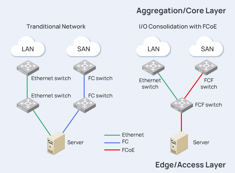
Fibre Channel over Ethernet, or FCoE, is a networking protocol that enables the convergence of traditional Fibre Channel storage networks with Ethernet-based data networks. This convergence is aimed at streamlining infrastructure, reducing costs, and enhancing overall network efficiency.

  • Historical Context

The development of FCoE can be traced back to the need for a more unified and simplified networking environment. Traditionally, Fibre Channel and Ethernet operated as separate entities, each with its own set of protocols and infrastructure. FCoE emerged as a solution to bridge the gap between these two technologies, offering a more integrated and streamlined approach to data storage and transfer.

  • Key Components

At its core, FCoE is a fusion of Fibre Channel and Ethernet technologies. The key components include Converged Network Adapters (CNAs), which allow for the transmission of both Fibre Channel and Ethernet traffic over a single network link. Additionally, FCoE employs a specific protocol stack that facilitates the encapsulation and transport of Fibre Channel frames within Ethernet frames.

How does Fibre Channel over Ethernet Work?

  • Convergence of Fibre Channel and Ethernet

The fundamental principle behind FCoE is the convergence of Fibre Channel and Ethernet onto a shared network infrastructure. This convergence is achieved through the use of CNAs, specialized network interface cards that support both Fibre Channel and Ethernet protocols. By consolidating these technologies, FCoE eliminates the need for separate networks, reducing complexity and improving resource utilization.

  • Protocol Stack Overview

FCoE utilizes a layered protocol stack to encapsulate Fibre Channel frames within Ethernet frames. This stack includes the Fibre Channel over Ethernet Initialization Protocol (FIP), which plays a crucial role in the discovery and initialization of FCoE-capable devices. The encapsulation process allows Fibre Channel traffic to traverse Ethernet networks seamlessly.

  • FCoE vs. Traditional Fibre Channel

Comparing FCoE with traditional Fibre Channel reveals distinctive differences in their approaches to data networking. While traditional Fibre Channel relies on dedicated storage area networks (SANs), FCoE leverages Ethernet networks for both data and storage traffic. This fundamental shift impacts factors such as infrastructure complexity, cost, and overall network design.


” Also Check – IP SAN (IP Storage Area Network) vs. FCoE (Fibre Channel over Ethernet) | FS Community

What are the Advantages of Fibre Channel over Ethernet?

  1. Enhanced Network Efficiency

FCoE optimizes network efficiency by combining storage and data traffic on a single network. This consolidation reduces the overall network complexity and enhances the utilization of available resources, leading to improved performance and reduced bottlenecks.

  1. Cost Savings

One of the primary advantages of FCoE is the potential for cost savings. By converging Fibre Channel and Ethernet, organizations can eliminate the need for separate infrastructure and associated maintenance costs. This not only reduces capital expenses but also streamlines operational processes.

  1. Scalability and Flexibility

FCoE provides organizations with the scalability and flexibility needed in dynamic IT environments. The ability to seamlessly integrate new devices and technologies into the network allows for future expansion without the constraints of traditional networking approaches.

Conclusion

In conclusion, FCoE stands as a transformative technology that bridges the gap between Fibre Channel and Ethernet, offering enhanced efficiency, cost savings, and flexibility in network design. As businesses navigate the complexities of modern networking, understanding FCoE becomes essential for those seeking a streamlined and future-ready infrastructure.


Related Articles: Demystifying IP SAN: A Comprehensive Guide to Internet Protocol Storage Area Networks

What Is Layer 4 Switch and How Does It Work?

What’s Layer 4 Switch?

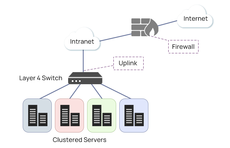
A Layer 4 switch, also known as a transport layer switch or content switch, operates on the transport layer (Layer 4) of the OSI (Open Systems Interconnection) model. This layer is responsible for end-to-end communication and data flow control between devices across a network.Here are key characteristics and functionalities of Layer 4 switches:

  • Packet Filtering: Layer 4 switches can make forwarding decisions based on information from the transport layer, including source and destination port numbers. This allows for more sophisticated filtering than traditional Layer 2 (Data Link Layer) or Layer 3 (Network Layer) switches.
  • Load Balancing: One of the significant features of Layer 4 switches is their ability to distribute network traffic across multiple servers or network paths. This load balancing helps optimize resource utilization, enhance performance, and ensure high availability of services.
  • Session Persistence: Layer 4 switches can maintain session persistence, ensuring that requests from the same client are consistently directed to the same server. This is crucial for applications that rely on continuous connections, such as e-commerce or real-time communication services.
  • Connection Tracking: Layer 4 switches can track the state of connections, helping to make intelligent routing decisions. This is particularly beneficial in scenarios where connections are established and maintained between a client and a server.
  • Quality of Service (QoS): Layer 4 switches can prioritize network traffic based on the type of service or application. This ensures that critical applications receive preferential treatment in terms of bandwidth and response time.
  • Security Features: Layer 4 switches often come with security features such as access control lists (ACLs) and the ability to perform deep packet inspection. These features contribute to the overall security of the network by allowing or denying traffic based on specific criteria.
  • High Performance: Layer 4 switches are designed for high-performance networking. They can efficiently handle a large number of simultaneous connections and provide low-latency communication between devices.

Layer 2 vs Layer 3 vs Layer 4 Switch

Layer 2 Switch:

Layer 2 switches operate at the Data Link Layer (Layer 2) and are primarily focused on local network connectivity. They make forwarding decisions based on MAC addresses in Ethernet frames, facilitating basic switching within the same broadcast domain. VLAN support allows for network segmentation.

However, Layer 2 switches lack traditional IP routing capabilities, making them suitable for scenarios where simple switching and VLAN segmentation meet the networking requirements.

Layer 3 Switch:

Operating at the Network Layer (Layer 3), Layer 3 switches combine switching and routing functionalities. They make forwarding decisions based on both MAC and IP addresses, supporting IP routing for communication between different IP subnets. With VLAN support, these switches are versatile in interconnecting multiple IP subnets within an organization.

Layer 3 switches can make decisions based on IP addresses and support dynamic routing protocols like OSPF and RIP, making them suitable for more complex network environments.

Layer 4 Switch:

Layer 4 switches operate at the Transport Layer (Layer 4), building on the capabilities of Layer 3 switches with advanced features. In addition to considering MAC and IP addresses, Layer 4 switches incorporate port numbers at the transport layer. This allows for the optimization of traffic flow, making them valuable for applications with high performance requirements.

Layer 4 switches support features such as load balancing, session persistence, and Quality of Service (QoS). They are often employed to enhance application performance, provide advanced traffic management, and ensure high availability in demanding network scenarios.

Summary:

In summary, Layer 2 switches focus on basic local connectivity and VLAN segmentation. Layer 3 switches, operating at a higher layer, bring IP routing capabilities and are suitable for interconnecting multiple IP subnets. Layer 4 switches, operating at the Transport Layer, further extend capabilities by optimizing traffic flow and offering advanced features like load balancing and enhanced QoS.

The choice between these switches depends on the specific networking requirements, ranging from simple local connectivity to more complex scenarios with advanced routing and application performance needs.


” Also Check – Layer 2, Layer 3 & Layer 4 Switch: What’s the Difference?

Layer 2 vs Layer 3 vs Layer 4 Switch: Key Parameters to Consider When Purchasing

To make an informed decision for your business, it’s essential to consider the key parameters between Layer 2, Layer 3, and Layer 4 switches when purchasing.

  1. Network Scope and Size:

When considering the purchase of switches, the size and scope of your network are critical factors. Layer 2 switches are well-suited for local network connectivity and smaller networks with straightforward topologies.

In contrast, Layer 3 switches come into play for larger networks with multiple subnets, offering essential routing capabilities between different LAN segments.

Layer 4 switches, with advanced traffic optimization features, are particularly beneficial in more intricate network environments where optimizing traffic flow is a priority.

  1. Functionality and Use Cases:

The functionality of the switch plays a pivotal role in meeting specific network needs. Layer 2 switches provide basic switching and VLAN support, making them suitable for scenarios requiring simple local connectivity and network segmentation.

Layer 3 switches, with combined switching and routing capabilities, excel in interconnecting multiple IP subnets and routing between VLANs.

Layer 4 switches take functionality a step further, offering advanced features such as load balancing, session persistence, and Quality of Service (QoS), making them indispensable for optimizing traffic flow and supporting complex use cases.

  1. Routing Capabilities:

Understanding the routing capabilities of each switch is crucial. Layer 2 switches lack traditional IP routing capabilities, focusing primarily on MAC address-based forwarding.

Layer 3 switches, on the other hand, support basic IP routing, allowing communication between different IP subnets.

Layer 4 switches, while typically not performing traditional IP routing, specialize in optimizing traffic flow at the transport layer, enhancing the efficiency of data transmission.

  1. Scalability and Cost:

The scalability of the switch is a key consideration, particularly as your network grows. Layer 2 switches may have limitations in larger networks, while Layer 3 switches scale well for interconnecting multiple subnets.

Layer 4 switch scalability depends on specific features and capabilities. Cost is another crucial factor, with Layer 2 switches generally being more cost-effective compared to Layer 3 and Layer 4 switches. The decision here involves balancing your budget constraints with the features required for optimal network performance.

  1. Security Features:

Security is paramount in any network. Layer 2 switches provide basic security features like port security. Layer 3 switches enhance security with the inclusion of access control lists (ACLs) and IP security features.

Layer 4 switches may offer additional security features, including deep packet inspection, providing a more robust defense against potential threats.

In conclusion, when purchasing switches, carefully weighing factors such as network scope, functionality, routing capabilities, scalability, cost, and security features ensures that the selected switch aligns with the specific requirements of your network, both in the present and in anticipation of future growth and complexities.

The Future of Layer 4 Switch

The future development of Layer 4 switches is expected to revolve around addressing the growing complexity of modern networks. Enhanced application performance, better support for cloud environments, advanced security features, and alignment with virtualization and SDN trends are likely to shape the evolution of Layer 4 switches, ensuring they remain pivotal components in optimizing and securing network infrastructures.


In conclusion, the decision between Layer 2, Layer 3, and Layer 4 switches is pivotal for businesses aiming to optimize their network infrastructure. Careful consideration of operational layers, routing capabilities, functionality, and use cases will guide you in selecting the switch that aligns with your specific needs. Whether focusing on basic connectivity, IP routing, or advanced traffic optimization, choosing the right switch is a critical step in ensuring a robust and efficient network for your business.


Related Article: Layer 2 vs Layer 3 Switch: Which One Do You Need? | FS Community

400G Data Center Deployment Challenges and Solutions

As technology advances, specific industry applications such as video streaming, AI, and data analytics are increasingly pushing for increased data speeds and massive bandwidth demands. 400G technology, with its next-gen optical transceivers, brings a new user experience with innovative services that allow for faster and more data processing at a time.

Large data centers and enterprises struggling with data traffic issues embrace 400G solutions to improve operational workflows and ensure better economics. Below is a quick overview of the rise of 400G, the challenges of deploying this technology, and the possible solutions.

The Rise of 400G Data Centers

The rapid transition to 400G in several data centers is changing how networks are designed and built. Some of the key drivers of this next-gen technology are cloud computing, video streaming, AI, and 5G, which have driven the demand for high-speed, high-bandwidth, and highly scalable solutions. The large amount of data generated by smart devices, the Internet of Things, social media, and other As-a-Service models are also accelerating this 400G transformation.

The major benefits of upgrading to a 400G data center are the increased data capacity and network capabilities required for high-end deployments. This technology also delivers more power, efficiency, speed, and cost savings. A single 400G port is considerably cheaper than four individual 100G ports. Similarly, the increased data speeds allow for convenient scale-up and scale-out by providing high-density, reliable, and low-cost-per-bit deployments.

How 400G Works

Before we look at the deployment challenges and solutions, let’s first understand how 400G works. First, the actual line rate or data transmission speed of a 400G Ethernet link is 425 Gbps. The extra 25 bits establish a forward error connection (FEC) procedure, which detects and corrects transmission errors.

400G adopts the 4-level pulse amplitude modulation (PAM4) to combine higher signal and baud rates. This increases the data rates four-fold over the current Non-Return to Zero (NRZ) signaling. With PAM4, operators can implement four lanes of 100G or eight lanes of 50G for different form factors (i.e., OSFP and QSFP-DD). This optical transceiver architecture supports transmission of up to 400 Gbit/s over either parallel fibers or multiwavelength.

PM4
PAM4

Deployment Challenges & Solutions

Interoperability Between Devices

The PAM4 signaling introduced with 400G deployments creates interoperability issues between the 400G ports and legacy networking gear. That is, the existing NRZ switch ports and transceivers aren’t interoperable with PAM4. This challenge is widely experienced when deploying network breakout connections between servers, storage, and other appliances in the network.

400G transceiver transmits and receives with 4 lanes of 100G or 8 lanes of 50G with PAM4 signaling on both the electrical and optical interfaces. However, the legacy 100G transceivers are designed on 4 lanes of 25G NRZ signaling on the electrical and optical sides. These two are simply not interoperable and call for a transceiver-based solution.

One such solution is the 100G transceivers that support 100G PAM4 on the optical side and 4X25G NRZ on the electrical side. This transceiver performs the re-timing between the NRZ and PAM4 modulation within the transceiver gearbox. Examples of these transceivers are the QSFP28 DR and FR, which are fully interoperable with legacy 100G network gear, and QSFP-DD DR4 & DR4+ breakout transceivers. The latter are parallel series modules that accept an MPO-12 connector with breakouts to LC connectors to interface FR or DR transceivers.

NRZ & PM4
Interoperability Between Devices

Excessive Link Flaps

Link flaps are faults that occur during data transmission due to a series of errors or failures on the optical connection. When this occurs, both transceivers must perform auto-negotiation and link training (AN-LT) before data can flow again. If link flaps frequently occur, i.e., several times per minute, it can negatively affect throughput.

And while link flaps are rare with mature optical technologies, they still occur and are often caused by configuration errors, a bad cable, or defective transceivers. With 400GbE, link flaps may occur due to heat and design issues with transceiver modules or switches. Properly selecting transceivers, switches, and cables can help solve this link flaps problem.

Transceiver Reliability

Some optical transceiver manufacturers face challenges staying within the devices’ power budget. This results in heat issues, which causes fiber alignment challenges, packet loss, and optical distortions. Transceiver reliability problems often occur when old QSFP transceiver form factors designed for 40GbE are used at 400GbE.

Similar challenges are also witnessed with newer modules used in 400GbE systems, such as the QSFP-DD and CFP8 form factors. A solution is to stress test transceivers before deploying them in highly demanding environments. It’s also advisable to prioritize transceiver design during the selection process.

Deploying 400G in Your Data Center

Keeping pace with the ever-increasing number of devices, users, and applications in a network calls for a faster, high-capacity, and more scalable data infrastructure. 400G meets these demands and is the optimal solution for data centers and large enterprises facing network capacity and efficiency issues. The successful deployment of 400G technology in your data center or organization depends on how well you have articulated your data and networking needs.

Upgrading your network infrastructure can help relieve bottlenecks from speed and bandwidth challenges to cost constraints. However, making the most of your network upgrades depends on the deployment procedures and processes. This could mean solving the common challenges and seeking help whenever necessary.

A rule of thumb is to enlist the professional help of an IT expert who will guide you through the 400G upgrade process. The IT expert will help you choose the best transceivers, cables, routers, and switches to use and even conduct a thorough risk analysis on your entire network. That way, you’ll upgrade appropriately based on your network needs and client demands.
Article Source: 400G Data Center Deployment Challenges and Solutions
Related Articles:

NRZ vs. PAM4 Modulation Techniques
400G Multimode Fiber: 400G SR4.2 vs 400G SR8
Importance of FEC for 400G

How to Utilize Data Center Space More Effectively?

What is data center space?

Data center space refers to the area of leased space available for servers to be stored in a data facility, including racks, cabinets, private suits, etc. It typically monitors all electrical and mechanical systems 24 hours a day, seven days a week. Nowadays, more and more companies choose data centers with larger space to meet their growing storage requirements.

However, many enterprises today encounter the challenges of limited data center space. One of the reasons is that the advancement of technology increases their demands for larger data center space, but it will cost a lot to build a new data center. Another factor is the underutilization of data center space. According to the research from an energy consortium called The Green Gird, 43 percent of respondents said they had no strategies in place to boost energy efficiency.

Therefore, it is necessary to learn some strategies to optimize the available space of data centers. Here are ten ways to make the best use of data center space.

How to utilize data center space?

  • Combine white space and gray space: Data center white space refers to the space where IT equipment and infrastructure are located, while data center gray space means the space where back-end equipment is located. By consolidating these two types of data center space, enterprises can use some technologies like cloud computing, which can save a large amount of space in data centers.
  • Refresh technologies: To improve data center space efficiency, technologies must be upgraded to minimize power consumption. For instance, new technologies like flywheels can increase the power of the machine, reducing the number of batteries required for the power supply. Besides, replacing the old and inefficient servers with new and energy-efficient servers can improve operational efficiency and reduce power consumption.
  • Use the smaller-diameter cable: Choosing the right cables is also an essential factor that should be considered. Tangled cables may cause cable congestion and then impede airflow. To prevent data center space from that problem, it’s necessary to use cables with smaller diameters, such as FS high-density fiber cables, which are more space-saving. They also allow rack space to be used to accommodate more equipment and reduce the demand for more cable management systems.smaller-diameter cable
  • Try virtualization solutions: According to the U.S. Environmental Protection Agency, most high-capacity servers are utilized at 15% or less, wasting space and power. Using virtualization technologies can reduce the number of new servers required to replace inefficient servers by sharing workloads among multiple servers, which can maximize data center space utilization.
  • Improve architecture efficiency: Data center architecture and the way that hardware is deployed have a vital impact on data center space. Terrible deployment may impede energy efficiency and lead to heating problems. Therefore, when planning a new data center, it is important to consider carefully the current design, future servers, and equipment, and how these devices will integrate with each other.
  • Optimize vertical space: Compared with horizontal data center space, making use of vertical space can increase the capacity and density of the data center without occupying floor space. Traditional racks and cabinets support from 42U to 45U of rack space, while taller racks offer up to 58U of rack space. Besides, it’s more efficient to use the space above the rack to patch the racks and cabinets.vertical space
  • Increase cabinet power density: Server racks and cabinets take up a lot of space, so it’s essential to make the best use of them. By increasing cabinet power density, the requirements for cabinets will be reduced, thus lessening the occupied floor space. Besides, this can also reduce management equipment and increase companies’ return on investment.
  • Use cooling technologies: Cooling accounts for about half of a data center’s entire energy consumption. Since computer room air conditioning (CRAC) and air handling units cannot handle the higher power densities, some companies may use liquid cooling systems, which take up a lot of valuable floor space. Using technologies like hot/cold aisle containment can save data center space to some extent while also maintaining suitable temperatures.

All the methods mentioned above work very well on boosting data center space utilization. The key is to choose a plan that best meets your goals and needs.

Article Source: How to Utilize Data Center Space More Effectively? | FS Community

Related Articles:

Data Center White Space and Gray Space | FS Community

What Is Data Center Storage? | FS Community