Category Archives: data center

Layer 2, Layer 3 & Layer 4 Switch: What’s the Difference?

Network switches are always seen in data centers for data transmission. Many technical terms are used with the switches. Have you ever noticed that they are often described as Layer 2, Layer 3 or even Layer 4 switch? What are the differences among these technologies? Which layer is better for deployment? Let’s explore the answers through this post.

What Does “Layer” Mean?

In the context of computer networking and communication protocols, the term “layer” is commonly associated with the OSI (Open Systems Interconnection) model, which is a conceptual framework that standardizes the functions of a telecommunication or computing system into seven abstraction layers. Each layer in the OSI model represents a specific set of tasks and functionalities, and these layers work together to facilitate communication between devices on a network.

The OSI model is divided into seven layers, each responsible for a specific aspect of network communication. These layers, from the lowest to the highest, are the Physical layer, Data Link layer, Network layer, Transport layer, Session layer, Presentation layer, and Application layer. The layering concept helps in designing and understanding complex network architectures by breaking down the communication process into manageable and modular components.

In practical terms, the “layer” concept can be seen in various networking devices and protocols. For instance, when discussing switches or routers, the terms Layer 2, Layer 3, or Layer 4 refer to the specific layer of the OSI model at which these devices operate. Layer 2 devices operate at the Data Link layer, dealing with MAC addresses, while Layer 3 devices operate at the Network layer, handling IP addresses and routing. Therefore, switches working on different layers of OSI model are described as Lay 2, Layer 3 or Layer 4 switches.
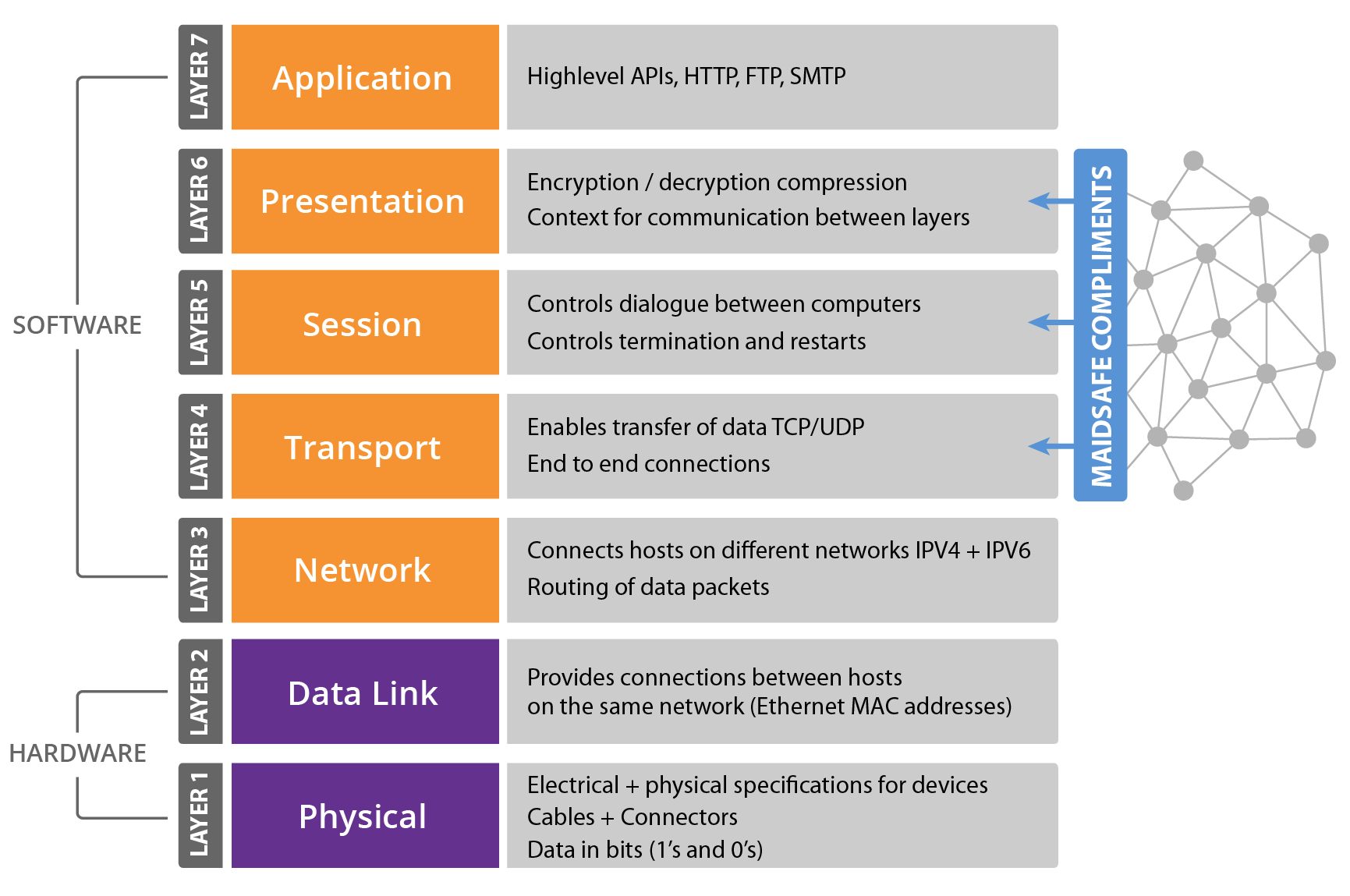
OSI model

Switch Layers

Layer 2 Switching

Layer 2 is also known as the data link layer. It is the second layer of OSI model. This layer transfers data between adjacent network nodes in a WAN or between nodes on the same LAN segment. It is a way to transfer data between network entities and detect or correct errors happened in the physical layer. Layer 2 switching uses the local and permanent MAC (Media Access Control) address to send data around a local area on a switch.
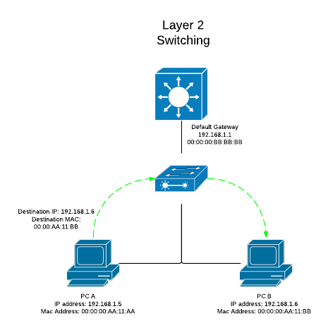
layer 2 switching

Layer 3 Switching

Layer 3 is the network layer in the OSI model for computer networking. Layer 3 switches are the fast routers for Layer 3 forwarding in hardware. It provides the approach to transfer variable-length data sequences from a source to a destination host through one or more networks. Layer 3 switching uses the IP (Internet Protocol) address to send information between extensive networks. IP address shows the virtual address in the physical world which resembles the means that your mailing address tells a mail carrier how to find you.
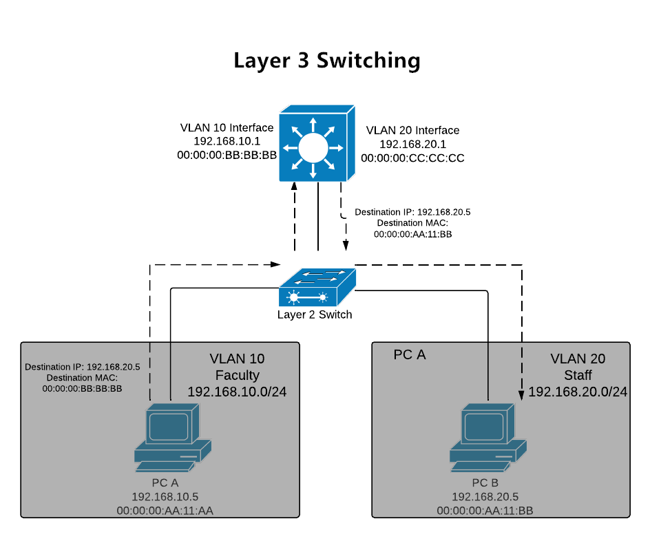
layer 3 switching

Layer 4 Switching

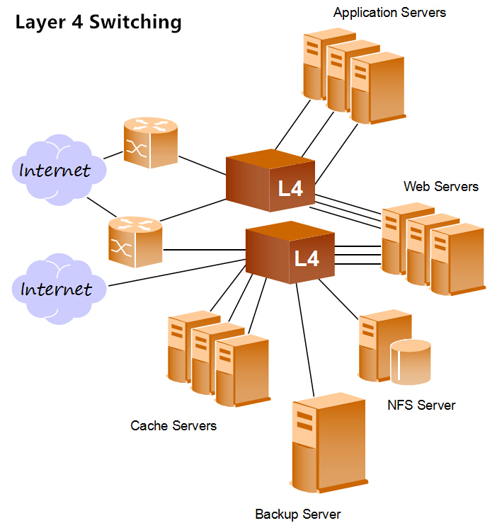
As the middle layer of OSI model, Layer 4 is the transport layer. This layer provides several services including connection-oriented data stream support, reliability, flow control, and multiplexing. Layer 4 uses the protocol of TCP (Transmission Control Protocol) and UDP (User Datagram Protocol) which include the port number information in the header to identify the application of the packet. It is especially useful for dealing with network traffic since many applications adopt designated ports.
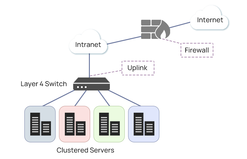
layer 4 switching

” Also Check –What Is Layer 4 Switch and How Does It Work?

Which Layer to Use?

The decision to use Layer 2, Layer 3, or Layer 4 switches depends on the specific requirements and characteristics of your network. Each type of switch operates at a different layer of the OSI model, offering distinct functionalities:

Layer 2 Switches:

Use Case: Layer 2 switches are appropriate for smaller networks or local segments where the primary concern is local connectivity within the same broadcast domain.

Example Scenario: In a small office or department with a single subnet, where devices need to communicate within the same local network, a Layer 2 switch is suitable.

Layer 3 Switches:

Use Case: Layer 3 switches are suitable for larger networks that require routing between different subnets or VLANs.

Example Scenario: In an enterprise environment with multiple departments or segments that need to communicate with each other, a Layer 3 switch facilitates routing between subnets.

Layer 4 Switches:

Use Case: Layer 4 switches are used when more advanced traffic management and control based on application-level information, such as port numbers, are necessary.

Example Scenario: In a data center where optimizing the flow of data, load balancing, and directing traffic based on specific applications (e.g., HTTP or HTTPS) are crucial, Layer 4 switches can be beneficial.

Considerations for Choosing:

  • Network Size: For smaller networks with limited routing needs, Layer 2 switches may suffice. Larger networks with multiple subnets benefit from the routing capabilities of Layer 3 switches.
  • Routing Requirements: If your network requires inter-VLAN communication or routing between different IP subnets, a Layer 3 switch is necessary.
  • Traffic Management: If your network demands granular control over traffic based on specific applications, Layer 4 switches provide additional capabilities.

In many scenarios, a combination of these switches may be used in a network, depending on the specific requirements of different segments. It’s common to have Layer 2 switches in access layers, Layer 3 switches in distribution or core layers for routing, and Layer 4 switches for specific applications or services that require advanced traffic management. Ultimately, the choice depends on the complexity, size, and specific needs of your network environment.

Conclusion

With the development of technologies, the intelligence of switches is continuously progressing on different layers of the network. The mix application of different layer switches (Layer 2, Layer 3 and Layer 4 switch) is a more cost-effective solution for big data centers. Understanding these switching layers can help you make better decisions.

Related Article:

Layer 2 vs Layer 3 Switch: Which One Do You Need? | FS Community

What Is FCoE and How Does It Work?

In the rapidly evolving landscape of networking technologies, one term gaining prominence is FCoE, or Fibre Channel over Ethernet. As businesses seek more efficient and cost-effective solutions, understanding the intricacies of FCoE becomes crucial. This article delves into the world of FCoE, exploring its definition, historical context, and key components to provide a comprehensive understanding of how it works.

What is FCoE (Fibre Channel over Ethernet)?

  • In-Depth Definition

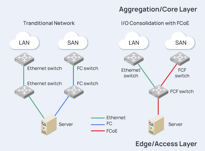
Fibre Channel over Ethernet, or FCoE, is a networking protocol that enables the convergence of traditional Fibre Channel storage networks with Ethernet-based data networks. This convergence is aimed at streamlining infrastructure, reducing costs, and enhancing overall network efficiency.

  • Historical Context

The development of FCoE can be traced back to the need for a more unified and simplified networking environment. Traditionally, Fibre Channel and Ethernet operated as separate entities, each with its own set of protocols and infrastructure. FCoE emerged as a solution to bridge the gap between these two technologies, offering a more integrated and streamlined approach to data storage and transfer.

  • Key Components

At its core, FCoE is a fusion of Fibre Channel and Ethernet technologies. The key components include Converged Network Adapters (CNAs), which allow for the transmission of both Fibre Channel and Ethernet traffic over a single network link. Additionally, FCoE employs a specific protocol stack that facilitates the encapsulation and transport of Fibre Channel frames within Ethernet frames.

How does Fibre Channel over Ethernet Work?

  • Convergence of Fibre Channel and Ethernet

The fundamental principle behind FCoE is the convergence of Fibre Channel and Ethernet onto a shared network infrastructure. This convergence is achieved through the use of CNAs, specialized network interface cards that support both Fibre Channel and Ethernet protocols. By consolidating these technologies, FCoE eliminates the need for separate networks, reducing complexity and improving resource utilization.

  • Protocol Stack Overview

FCoE utilizes a layered protocol stack to encapsulate Fibre Channel frames within Ethernet frames. This stack includes the Fibre Channel over Ethernet Initialization Protocol (FIP), which plays a crucial role in the discovery and initialization of FCoE-capable devices. The encapsulation process allows Fibre Channel traffic to traverse Ethernet networks seamlessly.

  • FCoE vs. Traditional Fibre Channel

Comparing FCoE with traditional Fibre Channel reveals distinctive differences in their approaches to data networking. While traditional Fibre Channel relies on dedicated storage area networks (SANs), FCoE leverages Ethernet networks for both data and storage traffic. This fundamental shift impacts factors such as infrastructure complexity, cost, and overall network design.


” Also Check – IP SAN (IP Storage Area Network) vs. FCoE (Fibre Channel over Ethernet) | FS Community

What are the Advantages of Fibre Channel over Ethernet?

  1. Enhanced Network Efficiency

FCoE optimizes network efficiency by combining storage and data traffic on a single network. This consolidation reduces the overall network complexity and enhances the utilization of available resources, leading to improved performance and reduced bottlenecks.

  1. Cost Savings

One of the primary advantages of FCoE is the potential for cost savings. By converging Fibre Channel and Ethernet, organizations can eliminate the need for separate infrastructure and associated maintenance costs. This not only reduces capital expenses but also streamlines operational processes.

  1. Scalability and Flexibility

FCoE provides organizations with the scalability and flexibility needed in dynamic IT environments. The ability to seamlessly integrate new devices and technologies into the network allows for future expansion without the constraints of traditional networking approaches.

Conclusion

In conclusion, FCoE stands as a transformative technology that bridges the gap between Fibre Channel and Ethernet, offering enhanced efficiency, cost savings, and flexibility in network design. As businesses navigate the complexities of modern networking, understanding FCoE becomes essential for those seeking a streamlined and future-ready infrastructure.


Related Articles: Demystifying IP SAN: A Comprehensive Guide to Internet Protocol Storage Area Networks

What Is Layer 4 Switch and How Does It Work?

What’s Layer 4 Switch?

A Layer 4 switch, also known as a transport layer switch or content switch, operates on the transport layer (Layer 4) of the OSI (Open Systems Interconnection) model. This layer is responsible for end-to-end communication and data flow control between devices across a network.Here are key characteristics and functionalities of Layer 4 switches:

  • Packet Filtering: Layer 4 switches can make forwarding decisions based on information from the transport layer, including source and destination port numbers. This allows for more sophisticated filtering than traditional Layer 2 (Data Link Layer) or Layer 3 (Network Layer) switches.
  • Load Balancing: One of the significant features of Layer 4 switches is their ability to distribute network traffic across multiple servers or network paths. This load balancing helps optimize resource utilization, enhance performance, and ensure high availability of services.
  • Session Persistence: Layer 4 switches can maintain session persistence, ensuring that requests from the same client are consistently directed to the same server. This is crucial for applications that rely on continuous connections, such as e-commerce or real-time communication services.
  • Connection Tracking: Layer 4 switches can track the state of connections, helping to make intelligent routing decisions. This is particularly beneficial in scenarios where connections are established and maintained between a client and a server.
  • Quality of Service (QoS): Layer 4 switches can prioritize network traffic based on the type of service or application. This ensures that critical applications receive preferential treatment in terms of bandwidth and response time.
  • Security Features: Layer 4 switches often come with security features such as access control lists (ACLs) and the ability to perform deep packet inspection. These features contribute to the overall security of the network by allowing or denying traffic based on specific criteria.
  • High Performance: Layer 4 switches are designed for high-performance networking. They can efficiently handle a large number of simultaneous connections and provide low-latency communication between devices.

Layer 2 vs Layer 3 vs Layer 4 Switch

Layer 2 Switch:

Layer 2 switches operate at the Data Link Layer (Layer 2) and are primarily focused on local network connectivity. They make forwarding decisions based on MAC addresses in Ethernet frames, facilitating basic switching within the same broadcast domain. VLAN support allows for network segmentation.

However, Layer 2 switches lack traditional IP routing capabilities, making them suitable for scenarios where simple switching and VLAN segmentation meet the networking requirements.

Layer 3 Switch:

Operating at the Network Layer (Layer 3), Layer 3 switches combine switching and routing functionalities. They make forwarding decisions based on both MAC and IP addresses, supporting IP routing for communication between different IP subnets. With VLAN support, these switches are versatile in interconnecting multiple IP subnets within an organization.

Layer 3 switches can make decisions based on IP addresses and support dynamic routing protocols like OSPF and RIP, making them suitable for more complex network environments.

Layer 4 Switch:

Layer 4 switches operate at the Transport Layer (Layer 4), building on the capabilities of Layer 3 switches with advanced features. In addition to considering MAC and IP addresses, Layer 4 switches incorporate port numbers at the transport layer. This allows for the optimization of traffic flow, making them valuable for applications with high performance requirements.

Layer 4 switches support features such as load balancing, session persistence, and Quality of Service (QoS). They are often employed to enhance application performance, provide advanced traffic management, and ensure high availability in demanding network scenarios.

Summary:

In summary, Layer 2 switches focus on basic local connectivity and VLAN segmentation. Layer 3 switches, operating at a higher layer, bring IP routing capabilities and are suitable for interconnecting multiple IP subnets. Layer 4 switches, operating at the Transport Layer, further extend capabilities by optimizing traffic flow and offering advanced features like load balancing and enhanced QoS.

The choice between these switches depends on the specific networking requirements, ranging from simple local connectivity to more complex scenarios with advanced routing and application performance needs.


” Also Check – Layer 2, Layer 3 & Layer 4 Switch: What’s the Difference?

Layer 2 vs Layer 3 vs Layer 4 Switch: Key Parameters to Consider When Purchasing

To make an informed decision for your business, it’s essential to consider the key parameters between Layer 2, Layer 3, and Layer 4 switches when purchasing.

  1. Network Scope and Size:

When considering the purchase of switches, the size and scope of your network are critical factors. Layer 2 switches are well-suited for local network connectivity and smaller networks with straightforward topologies.

In contrast, Layer 3 switches come into play for larger networks with multiple subnets, offering essential routing capabilities between different LAN segments.

Layer 4 switches, with advanced traffic optimization features, are particularly beneficial in more intricate network environments where optimizing traffic flow is a priority.

  1. Functionality and Use Cases:

The functionality of the switch plays a pivotal role in meeting specific network needs. Layer 2 switches provide basic switching and VLAN support, making them suitable for scenarios requiring simple local connectivity and network segmentation.

Layer 3 switches, with combined switching and routing capabilities, excel in interconnecting multiple IP subnets and routing between VLANs.

Layer 4 switches take functionality a step further, offering advanced features such as load balancing, session persistence, and Quality of Service (QoS), making them indispensable for optimizing traffic flow and supporting complex use cases.

  1. Routing Capabilities:

Understanding the routing capabilities of each switch is crucial. Layer 2 switches lack traditional IP routing capabilities, focusing primarily on MAC address-based forwarding.

Layer 3 switches, on the other hand, support basic IP routing, allowing communication between different IP subnets.

Layer 4 switches, while typically not performing traditional IP routing, specialize in optimizing traffic flow at the transport layer, enhancing the efficiency of data transmission.

  1. Scalability and Cost:

The scalability of the switch is a key consideration, particularly as your network grows. Layer 2 switches may have limitations in larger networks, while Layer 3 switches scale well for interconnecting multiple subnets.

Layer 4 switch scalability depends on specific features and capabilities. Cost is another crucial factor, with Layer 2 switches generally being more cost-effective compared to Layer 3 and Layer 4 switches. The decision here involves balancing your budget constraints with the features required for optimal network performance.

  1. Security Features:

Security is paramount in any network. Layer 2 switches provide basic security features like port security. Layer 3 switches enhance security with the inclusion of access control lists (ACLs) and IP security features.

Layer 4 switches may offer additional security features, including deep packet inspection, providing a more robust defense against potential threats.

In conclusion, when purchasing switches, carefully weighing factors such as network scope, functionality, routing capabilities, scalability, cost, and security features ensures that the selected switch aligns with the specific requirements of your network, both in the present and in anticipation of future growth and complexities.

The Future of Layer 4 Switch

The future development of Layer 4 switches is expected to revolve around addressing the growing complexity of modern networks. Enhanced application performance, better support for cloud environments, advanced security features, and alignment with virtualization and SDN trends are likely to shape the evolution of Layer 4 switches, ensuring they remain pivotal components in optimizing and securing network infrastructures.


In conclusion, the decision between Layer 2, Layer 3, and Layer 4 switches is pivotal for businesses aiming to optimize their network infrastructure. Careful consideration of operational layers, routing capabilities, functionality, and use cases will guide you in selecting the switch that aligns with your specific needs. Whether focusing on basic connectivity, IP routing, or advanced traffic optimization, choosing the right switch is a critical step in ensuring a robust and efficient network for your business.


Related Article: Layer 2 vs Layer 3 Switch: Which One Do You Need? | FS Community
How Is 5G Pushing the 400G Network Transformation?

With the rapid technological disruption and the wholesale shift to digital, several organizations are now adopting 5G networks, thanks to the fast data transfer speeds and improved network reliability. The improved connectivity also means businesses can expand on their service delivery and even enhance user experiences, increasing market competitiveness and revenue generated.

Before we look at how 5G is driving the adoption of 400G transformation, let’s first understand what 5G and 400G are and how the two are related.

What is 5G?

5G is the latest wireless technology that delivers multi-Gbps peak data speeds and ultra-low latency. This technology marks a massive shift in communication with the potential to greatly transform how data is received and transferred. The increased reliability and a more consistent user experience also enable an array of new applications and use cases extending beyond network computing to include distributed computing.

And while the future of 5G is still being written, it’s already creating a wealth of opportunities for growth & innovation across industries. The fact that tech is constantly evolving and that no one knows exactly what will happen next is perhaps the fascinating aspect of 5G and its use cases. Whatever the future holds, one is likely certain: 5G will provide far more than just a speedier internet connection. It has the potential to disrupt businesses and change how customers engage and interact with products and services.

What is 400G?

400G or 400G Ethernet is the next generation of cloud infrastructure that offers a four-fold jump in max data-transfer speed from the standard maximum of 100G. This technology addresses the tremendous bandwidth demands on network infrastructure providers, partly due to the massive adoption of digital transformation initiatives.

Additionally, exponential data traffic growth driven by cloud storage, AI, and Machine Learning use cases has seen 400G become a key competitive advantage in the networking and communication world. Major data centers are also shifting to quicker, more scalable infrastructures to keep up with the ever-growing number of users, devices, and applications. Hence high-capacity connection is becoming quite critical.

How are 5G and 400G Related?

The 5G wireless technology, by default, offers greater speeds, reduced latencies, and increased data connection density. This makes it an attractive option for highly-demanding applications such as industrial IoT, smart cities, autonomous vehicles, VR, and AR. And while the 5G standard is theoretically powerful, its real-world use cases are only as good as the network architecture this wireless technology relies on.

The low-latency connections required between devices, data centers, and the cloud demands a reliable and scalable implementation of the edge-computing paradigms. This extends further to demand greater fiber densification at the edge and substantially higher data rates on the existing fiber networks. Luckily, 400G fills these networking gaps, allowing carriers, multiple-system operators (MSOs), and data center operators to streamline their operations to meet most of the 5G demands.

5G Use Cases Accelerating 400G transformation

As the demand for data-intensive services increases, organizations are beginning to see some business sense in investing in 5G and 400G technologies. Here are some of the major 5G applications driving 400G transformation.

High-Speed Video Streaming

The rapid adoption of 5G technology is expected to take the over-the-top viewing experience to a whole new level as demand for buffer-free video streaming, and high-quality content grows. Because video consumes the majority of mobile internet capacity today, the improved connectivity will give new opportunities for digital streaming companies. Video-on-demand (VOD) enthusiasts will also bid farewell to video buffering, thanks to the 5G network’s ultra-fast download speeds and super-low latency. Still, 400G Ethernet is required to ensure reliable power, efficiency, and density to support these applications.

Virtual Gaming

5G promises a more captivating future for gamers. The network’s speed enhances high-definition live streaming, and thanks to ultra-low latency, 5G gaming won’t be limited to high-end devices with a lot of processing power. In other words, high-graphics games can be displayed and controlled by a mobile device; however, processing, retrieval, and storage can all be done in the cloud.

Use cases such as low-latency Virtual Reality (VR) apps, which rely on fast feedback and near-real-time response times to give a more realistic experience, also benefit greatly from 5G. And as this wireless network becomes the standard, the quantity and sophistication of these applications are expected to peak. That is where 400G data centers and capabilities will play a critical role.

The Internet of Things (IoT)

Over the years, IoT has grown and become widely adopted across industries, from manufacturing and production to security and smart home deployments. Today, 5G and IoT are poised to allow applications that would have been unthinkable a few years ago. And while this ultra-fast wireless technology promises low latency and high network capacity to overcome the most significant barriers to IoT proliferation, the network infrastructure these applications rely on is a key determining factor. Taking 5G and IoT to the next level means solving the massive bandwidth demands while delivering high-end flexibility that gives devices near real-time ability to sense and respond.

400G Network

400G Ethernet as a Gateway to High-end Optical Networks

Continuous technological improvements and the increasing amount of data generated call for solid network infrastructures that support fast, reliable, and efficient data transfer and communication. Not long ago, 100G and 200G were considered sophisticated network upgrades, and things are getting even better.

Today, operators and service providers that were among the first to deploy 400G are already reaping big from their investments. Perhaps one of the most compelling features of 400G isn’t what it offers at the moment but rather its ability to accommodate further upgrades to 800G and beyond. What’s your take on 5G and 400G, or your progress in deploying these novel technologies?

Article Source: How Is 5G Pushing the 400G Network Transformation?

Related Articles:

Typical Scenarios for 400G Network: A Detailed Look into the Application Scenarios

What’s the Current and Future Trend of 400G Ethernet?

How 400G Has Transformed Data Centers

With the rapid technological adoption witnessed in various industries across the world, data centers are adapting on the fly to keep up with the rising client expectations. History is also pointing to a data center evolution characterized by an ever-increasing change in fiber density, bandwidth, and lane speeds.

Data centers are shifting from 100G to 400G technologies in a bid to create more powerful networks that offer enhanced experiences to clients. Some of the factors pushing for 400G deployments include recent advancements in disruptive technologies such as AI, 5G, and cloud computing.

Today, forward-looking data centers that want to maximize cost while ensuring high-end compatibility and convenience have made 400G Ethernet a priority. Below, we have discussed the evolution of data centers, the popular 400G form factors, and what to expect in the data center switching market as technology continues to improve.

Evolution of Data Centers

The concept of data centers dates back to the 1940s, when the world’s first programmable computer, the Electronic Numerical Integrator and Computer, or ENIAC, was the apex of computational technology. The latter was primarily used by the US army to compute artillery fire during the Second World War. It was complex to maintain and operate and was only operated in a particular environment.

This saw the development of the first data centers centered on intelligence and secrecy. Ideally, a data center would have a single door and no windows. And besides the hundreds of feet of wiring and vacuum tubes, huge vents and fans were required for cooling. Refer to our data center evolution infographic to learn more about the rise of modern data centers and how technology has played a huge role in shaping the end-user experience.data center evolution

The Limits of Ordinary Data Centers

Some of the notable players driving the data center evolution are CPU design companies like Intel and AMD. The two have been advancing processor technologies, and both boost exceptional features that can support any workload.

And while most of these data center processors are reliable and optimized for several applications, they aren’t engineered for the specialized workloads that are coming up like big data analytics, machine learning, and artificial intelligence.

How 400G Has Transformed Data Centers

The move to 400 Gbps drastically transforms how data centers and data center interconnect (DCI) networks are engineered and built. This shift to 400G connections is more of a speculative and highly-dynamic game between the client and networking side.

Currently, two multisource agreements compete for the top spot as a form-factor of choice among consumers in the rapidly evolving 400G market. The two technologies are QSFP-DD and OSFP optical/pluggable transceivers.

OSFP vs. QSFP-DD

QSFP-DD is the most preferred 400G optical form factor on the client-side, thanks to the various reach options available. The emergence of the Optical Internetworking Forum’s 400ZR and the trend toward combining switching and transmission in one box are the two factors driving the network side. Here, the choice of form factors narrows down to power and mechanics.

The OSFP being a bigger module, provides lots of useful space for DWDM components, plus it features heat dissipation capabilities up to 15W of power. When putting coherent capabilities into a small form factor, power is critical. This gives OSFP a competitive advantage on the network side.

And despite the OSFP’s power, space, and enhanced signal integrity performance, it’s not compatible with QSFP28 plugs. Additionally, its technology doesn’t have the 100Gbps version, so it cannot provide an efficient transition from legacy modules. This is another reason it has not been widely adopted on the client side.

However, the QSFP-DD is compatible with QSFP28 and QSFP plugs and has seen a lot of support in the market. The only challenge is its low power dissipation, often capped at 12 W. This makes it challenging to efficiently handle a coherent ASIC (application-specific integrated circuit) and keep it cool for an extended period.

The switch to 400GE data centers is also fueled by the server’s adoption of 25GE/50GE interfaces to meet the ever-growing demand for high-speed storage access and a vast amount of data processing.OSFP vs. QSFP-DD

The Future of 400G Data Center Switches

Cloud service provider companies such as Amazon, Facebook, and Microsoft are still deploying 100G to reduce costs. According to a report by Dell’Oro Group, 100G is expected to peak in the next two years. But despite 100G dominating the market now, 400G shipments are expected to surpass 15M million switch ports by 2023.

In 2018, the first batch of 400G switch systems based on 12.8 Tbps chips was released. Google, which then was the only cloud service provider, was among the earliest companies to get into the market. Fast-forward, other cloud service providers have entered the market helping fuel the transformation even further. Today, cloud service companies make a big chunk of 400G customers, but service providers are expected to be next in line.

Choosing a Data Center Switch

Data center switches are available in a range of form factors, designs, and switching capabilities. Depending on your unique use cases, you want to choose a reliable data center switch that provides high-end flexibility and is built for the environment in which they are deployed. Some of the critical factors to consider during the selection process are infrastructure scalability and ease of programmability. A good data center switch is power efficient with reliable cooling and should allow for easy customization and integration with automated tools and systems. Here is an article about Data Center Switch Wiki, Usage and Buying Tips.

Article Source: How 400G Has Transformed Data Centers

Related Articles:

What’s the Current and Future Trend of 400G Ethernet?

400ZR: Enable 400G for Next-Generation DCI