Tag Archives: CWDM DWDM

We all know that cascaded FCP/FICON directors use ISLs to connect the directors

Inter-Switch Link (ISL) protocol, is a cisco proprietary protocol, Can only be used for interconnection between Cisco network equipment, it is mainly used for maintenance the VLAN information such as the traffic between the switches and routers. VLAN is a kind of agreement for solving the problem of Ethernet radio and safety. After the introduction of VLAN, the host to communicate across the switches in the VLAN. We all know that cascaded FCP/FICON directors use ISLs to connect the directors. In certain configurations, ISLs can be grouped or aggregated, typically for performance and reliability. Brocade calls this an ISL trunk (frame-based trunking), and Cisco calls this a Port Channel just as 8 way DWDM module. We will generically call this feature ISL trunking or just a trunk.

Each vendor might implement these trunks in a unique way to provide proprietary features. The vendors’ trunks ISLs might contain proprietary frames, proprietary frame formats, or special characters or sequences of characters in the inter-frame gaps. Often, the difference between a cascaded environment contained in a signal data center or campus environment, and one in a metro environment, is the use of a DWDM Optical Amplifiers to carry the ISLs over the extended distance. The primary concern when attempting to use trunked ISLs with a DWDM is that the ISL data streams must be unaltered by the DWDM for the proprietary functions to work correctly. This os sometimes called bits in, bits out, to indicate that there is no change to the signals, especially between the cascaded directors.
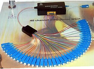
QQ图片20150512144634
The challenge with non-symmetric transit times for the ISLs in a trunk is illustrated in following picture. The scale is time to arrive and not distance traversed per time unit (which would produce a great roughly the opposite of this). This diagram shows how the signals, sent at the same time on parallel ISLs, could arrive at the endpoint at different times. The director measure this difference at the time that the trunk is created. The difference is called skew. The director can accommodate a small skew, but an ISL with skew that is too large might be removes from the trunk by the director. An ISL that is carried on circuitry that introduces variable skew will not be detected, because the director does not re-measure the skew. If the variance of the skew becomes too large, the traffic on the trunk could be the cause of interface control checks (IFCCs), or could experience out-of-order frames.

It must be noted that the trunks between cascaded directors might appear to work without any issues during testing, because this is often performed with a relatively low I/O load. At that point, only oe or two ISLs in a trunk carry traffic with high I/O loads. Some DWDM Equipments features can cause the skew to vary (that is, not be consistent), which can cause out-of-order frames or other issues with the I/O traffic. Any alteration of the data stream introduced by circuitry or software in the DWDMs might affect the ISLs. The DWDM vendor might alter the data streams for different purposes. You should check with the DWDM and the FICON director vendors to determine basic ISL compatibility. Some of these features might be implemented in a way that alters the data stream that will not affect a single ISL, but would affect trunking. In general, these DWDM features should not be used on trunked ISLs. IBM has experience with DWDMs that could not be used for ISL trunks because of the issues noted, and some experience where ultra DWDM appeared to support ISL trunking. There are many features on each DWDM and on each FICON director, giving a large number of permutations that would be difficult to test. For a single example, and definitely not to provide an exhaustive test, Fiberstore tested a specific configuration with two Brocade FICON Directors whose trunked ISLs were carried on two ADVA FSP 3000s at a distance of 80 km. The test configuration, with significant and varying I/O load, did not find significant increases in IFCCs or out-of-order frames, and the skews between the ISLs in the trunk were within acceptable limits.


Related products:

The principle of optical fiber connector and classification

In optical fiber communication (transmission) link, in order to achieve the different modules.The needs of the flexible connection between devices and systems, there must be a able to removable between optical fiber and optical fiber (activities) of the connection device, can make the light path according to the required transmission channel, with the purpose of the implementation and complete reservation or expectations and requirements, can realize the function of the device is called a connector.Optical fiber connector is the fiber of two surface precision docking, so that the optical output of light energy to maximize the coupling to the receiving optical fiber, and optical link due to the intervention and to minimize the effects on the system, it is the basic requirement of optical fiber connector.To a certain extent, optical fiber connector also affects the reliability and the performance of optical transmission system.

A.Is the main optical fiber connection

1. The fixed connection.Mainly used for permanent connection between optical fiber in optical fiber cable line, with welding, also have use bonding and mechanical connection.Is characterized by low coupling loss, high mechanical strength.Equipment need welding machine, probably thousands of dollars.
2. Active connection.Is mainly used in optical fiber transmission system equipment and instrument connections between, mainly through the optical coupler plug connection.Is characterized by flexible joint is better, exchange connection is convenient, large loss and reflection is the lack of this connection.Now the insertion loss is already very good, dozens of RMB is ok, you can directly buy finished product, if you want to bulk, also need to face polishing grinding equipment, that is too expensive, suggested that direct buy jump line.
3. A temporary connection.Measure the tail fiber and measured coupling between optical fiber connection, connected by this method.Characteristic is convenient and flexible, low cost, low requirements for loss, temporary measure when use this way to connect more.Also can use welding machine or V groove with glue.

B. To optical fiber connection request

1. The requirements for fixed connection Optical fiber fixed connection cable line is a key technology.Demand for fixed connection has the following several aspects: coupling loss is small, good consistency;Coupling loss stability is better, general difference in temperature range should not have the generation of additional loss;Has enough mechanical strength and service life;Operation should be simple, easy to construction work;Joint to small volume, easy to place and protection;Low cost, material is easy to be processed.
2. The requirement of active connection For removable optical fiber connection, are now using mechanical connector.The requirement basically has the following several aspects: connection loss, single-mode fiber loss is less than 0.5 dB;Should have good repeatability and interchangeability.After repeatedly plug and interchangeable parts, there is still a good consistency;Has good stability, fittings insertion loss stability after fastening, not affected by temperature change;Smaller volume, weight light;Have certain strength;The price is suitable.
3. Optical fiber temporary connection to temporary connection request, also can use the welding machine welding.Require low loss as much as possible, in connection with V groove and capillary, must add liquid ratio, otherwise unable to eliminate the Fresnel reflection.3. Optical fiber connection loss factor

C.Optical fiber connection loss factor

After the fiber connection, light through joint parts will produce certain loss, known as optical fiber connecting the transmission loss, the splicing loss.The main analysis of single-mode fiber coupling loss factor.
1. The intrinsic factors on the connection is most affected by single mode optical fiber mode field diameter.When 20% of mode field diameter mismatch, will produce 0.2 dB over the loss.As far as possible the use of optical fiber mode field diameter smaller, to reduce the loss of connection has the vital significance.
2. The external factors outside the main factors of single-mode optical fiber connection loss for the axis displacement and axial tilt.For mechanical connection with vertical to the weld and the fiber core deformation and other factors.
(1) axis misalignment.When the dislocation at 1.2 microns, cause the loss of 0.5 dB, connected to the positioning accuracy, can effectively control the influence of the axial displacement.
(2) the axial tilt.When the tilt reaches 1 °, will cause a loss of 0.2 dB.Selects the high quality fiber cutting knife, can improve the axial tilt caused by wear and tear.
(3) the fiber core deformation.When the amount of current, advancing the automatic welding machine, discharge current, time set reasonable, such as fiber core deformation caused by the wastage can do below 0.02 dB.

D. Optical fiber connection method and comparison

1. The welding machine welding This method is mainly used for optical fiber joint connection, is currently used more in automatic welding machine for welding, welding machine points single core and multicore welding machine two kinds.Before formally succeeded, welding machine, the experiments of various parameters to determine the alignment precision of welding machine, discharge size, the quantity of various parameters, such as, to adapt it to the concrete in the specific working conditions of the fiber, the loss of control within a set of indicators.Succeeded completed, should be timely optical time-domain reflectometer to determine the loss, after the loss conform to the requirements of the indicators, before being reinforcing process, until the complete connection.
2. Mechanical connection By far the most common connection characteristics of three types of mechanical connector is as follows: process FO type connector.This kind of optical fiber connector is standard connection form of single core optical fiber.Most of the current product end face grinding to turn it into a ball, the convergence of the beams using optics refraction principle, reduce the loss of the connection.This kind of optical fiber connector multi-purpose on optical fiber distribution frame and test instrument, for transfer.NTT multicore fiber optic connectors.This kind of optical fiber connector can be connected a 12 optical fibers, has a large capacity, simple manufacturing process, and in place of low loss, therefore, in less demanding users to connect optical fiber has been widely used.This method used in optical fiber short distance relay, relay and users, the effect is better.Wire connector.With the development of technology, wiring son can do 0.1 dB below the average in loss and 50% of the splicing loss can be below 0.05 dB, adaptability to the environment temperature and humidity is relatively good.Due to this kind of connection method does not require expensive welding machine, and a single core and multicore specifications, convenient use and expects its prospect of application is more and more wide, make the connection of the fiber as convenient as cable.In the development of optical fiber communication technology is critical.Simplify the connection technology, improve the quality of connection, to expand fiber applications will play a positive role in promoting.

Related articles:CWDM DWDM,CWDM technology,CWDM Add Drop Multiplexer,WDM networks