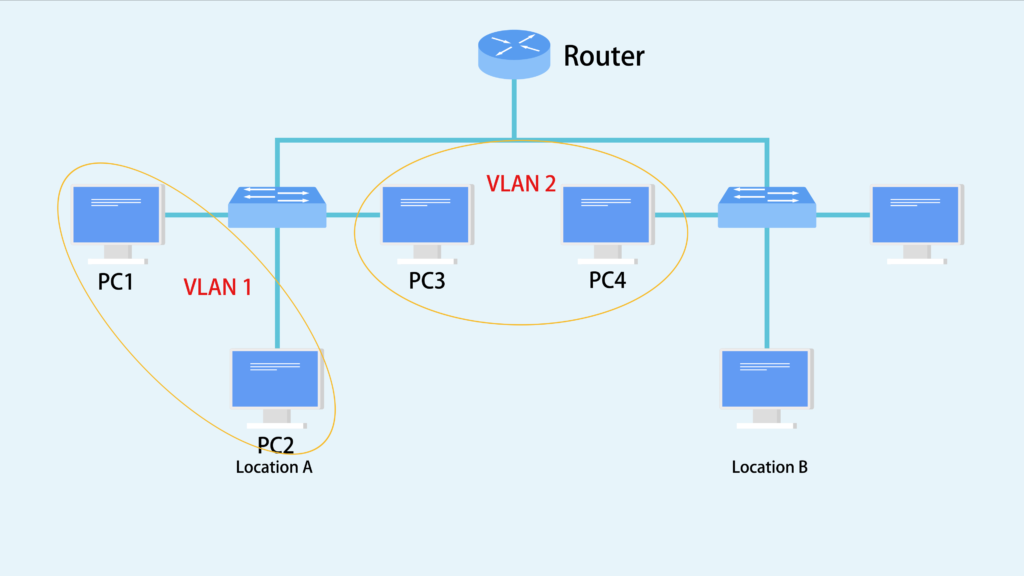
As networks grow larger and larger, scalability becomes an issue. Every device in the network needs to send broadcasts to communicate in a broadcast domain . As more devices are added to the broadcast domain, more broadcasts start to saturate the network. In this case, VLAN (Virtual LAN) is needed to separate broadcast domains virtually, eliminating the need to create completely separate hardware LANs to overcome this large-broadcast-domain issue. In this post, we’re gonna expound the motivators to deploy VLAN and how to set up VLAN configuration step by step.

Motivators to Implement VLAN
VLAN is a way of creating multiple virtual switches inside one physical data switch. There are a lot of reasons to implement VLAN, some of which are listed as follows.
- Link Utilization: Link utilization is another big reason to use VLANs. Spanning tree by function builds a single path through your layer 2 network to prevent loops. If you have multiple redundant links to your aggregating devices then some of these links will go unused. To get around this you can build multiple STP topology with different VLANs.
- Service Separation: If you have IP security cameras, IP Phones, and Desktops all connecting into the same switch it might be easier to separate these services out into their own subnet. This would also allow you to apply QoS markings to these services based on VLAN instead of some higher layer service. You can also apply ACLs on the device performing Layer 3 routing to prevent communication between VLANs that might not be desired.
- Subnet Size: If a single site becomes too large you can break that site down into different VLANs which will reduce the number of hosts that see need to process each broadcast.
VLAN Configuration Guidelines on Layer 3 Switch
Configuring two or more VLANs to communicate with each other requires the use of either a VLAN-aware router or a Layer 3 switch. VLAN configuration can be accomplished either in CLI interface or in Web interface. The following video is a VLAN configuration example on FS S5800/S5850 10 gigabit switch.
Here we take FS S5850-32S2Q Layer 3 switch as an example to configure VLAN. To create a VLAN via CLI interface, SecureCRT software is required to enter CLI interface, then perform the VLAN configuration command in the chart below:
| Procedure | Command | Purpose |
| Step 1 | Set the parameters of COM2 port | Quick connect on startup |
| Step 2 | #enter | Enter CLI interface |
| Step 3 | #configure terminal | Enter the global configure mode |
| Step 4 | #vlan database | Enter VLAN configure mode |
| Step 5 | #show vlan all | Check the details of all VLANs on the switch |
Configuring VLAN in Web Interface is quite simple. Just perform the following two steps and you would see the basic info of the VLAN that is created.
Step 1: Log in the Web user interface using the account and password
Step 2: Find the service management and create a new VLAN, and set its ID as 10 or 20.
Note: Ports configured to use VLAN 10 act as if they’re connected to the exact same switch. Ports in VLAN 20 can not directly talk to ports in VLAN 10. They must be routed between the two or have a link that bridges the two VLANs
Summary
VLAN deployments make it easy for network engineers to partition a single switched network to match the functional and security requirements of their systems without having to run new cables or make major changes in their current network infrastructure. The proper VLAN configuration on Layer 3 switches ensures reliable and secure data link access to all hosts connected to switch ports. Knowing more about VLAN configuration would allow you to use them when you need them and to use them correctly when you do.
Related Article: Voice VLAN Configuration Guidelines on Ethernet Switches
Related Article: VLAN: How Does It Change Your Network Management?
Related Article: QinQ vs VLAN vs VXLAN
