Category Archives: Fiber Patch Cable

Fiber Patch Cable Management

Deploying more fiber optic cable is just the first step to meet the high-bandwidth requirements, strong management over the fiber optic cable is a basic requirement for a successful fiber optic network infrastructure. Fiber patch cable might be the weakest link in optical network infrastructures. To deliver and guarantee and optimal network performance, patch cable management is critical. In addition, cable management of optical fiber can lower operation cost & time and increases the reliability and flexibility of network operation and maintenance. This post will offer the critical elements that should be noted during patch cable management, as well as tips for fiber patch cable management.

Elements That Affects Patch Cable Management

To get a flexible and well-organized patch cable management, the factors that affect the performance of the fiber optic patch cable should be introduced first. Here are four key elements that should be considered during patch cable management.

Bend Radius

Unlike copper, fiber optic made of glass is much fragile and need more protection and attention during the operation and management. Thus, the fiber’s bend radius will impact its reliability and performance. If a fiber cable is bent excessively, the optical signal within the cable may refract and escape through the fiber cladding which will cause a loss of signal strength and is known as bend loss. What’s more, bending, especially during the installation and pulling of fiber optic patch cable might also cause micro cracks and damage the fiber permanently. Generally, there are two basic types of bends in fiber, which are microbends and macrobends as shown in the following picture. The macrobends are larger than microbends.

bend radius

What should be noted is that bend radius might not be seen during the initial installation of fiber patch cable. This is because the number of patch cables routed to the optical distribution ODF is usually small. However, when more patch cords are added on the top of installed patch cables in the future the problems will come across (shown in the following picture). A fiber patch cable that working fine for years might suddenly have an increased level of attenuation, as well as a potentially shorter service life.

effect of adding cable

Path of Patch Cable

Patch cable path is an aspect closely related to bend radius that can affect the performance and maintenance of the patch cable. The path of the patch cable should be clearly defined and easy to follow. Improper cable routing can cause increased congestion in the termination panel, increasing the possibility of bend radius violations and long-term failure. However, the well-managed patch cable path ensures that bend radius requirements are maintained at all points and makes accessing individual patch cable easier, quicker and safer. What should be mentioned is that the well-organized fiber patch cords can help to decrease operating costs and the time required to turn-up or restore service.

Accessibility of Patch Cable

The third aspect is the accessibility of the installed patch cable. If the installed patch cable is easy to be accessed, the maintenance and operation would be quick without inducing a macrobend on an adjacent fiber, and it can also offer proper bend radius protection. Accessibility is critical during network reconfiguration operations and directly impacts operation costs and network reliability.

Physical Protection

Patch cables routed between pieces of equipment can largely affect network reliability. Without proper protection, they would be easy to be damaged by technicians and equipment accidentally. Thus, physical protection of the installed patch cords is very important.

Tips for Fiber Patch Cable Management

According to the mentioned aspects that can affect the performance and maintenance of the fiber optic patch cable, here offers several tips that can help to increase the performance of patch cords, as well as the reliability and flexibility of patch cable management.

Tip 1: Pay attention to the bend radius of the patch cable. Generally, for 1.6mm and 3.0mm cords, the minimum un-loaded bend radius is 3.5 cm, and the minimum bend radius of MPO patch cable is ten times the cord diameter.

bend radius of fiber optic

Tip 2: Never pull or stress the patch cords (shown in the following figure). During the patching process, excessive force can stress fiber patch cables and connectors attached to them, thus reducing their performance. There might be something wrong if you need to use force in pulling a cord.

pulling fiber patch cable

Tip 3: Routing cords through cable pathways. If the existing cord is the right length, it may be possible to re-use it. If this is the case, remove the cord completely and re-run it in through the cable pathways. This is the only sure way to ensure there are no tangles, kinks or strains in the cord. For efficient routing, find the best path between the ports to be connected. Avoid routing cords through troughs and guides that are already congested.

Tip 4: Bundling and tying cords give the panel a neat appearance but tight bundling increases the risk of pinching (as shown in the following figure). Do not tighten cable ties beyond the point where individual cords can rotate freely.

cable management

Tip 5: Labeling is necessary. Labeling is the most important part of a System Administrator’s responsibilities. At any administration point in a cabling infrastructure, including patch panel, accurate labels are essential. These will identify pair modularity and tell technicians where the other end of the cable is terminated.

Tip 6: Inspect fiber cords for physical damage including stress marks from sharp bends on the sheath, or damage to connectors as shown in the following figure.

physical damage

Conclusion

A strong and successful patch cable management which can increase the reliability and flexibility and decrease the cost of network operation and maintenance should provide bend radius protection, reasonable patch cable path, easy accessibility of patch cable and physical protection. When the four mentioned aspects are satisfied, there is already half the success of strong patch cable management.

Source: http://www.fs.com/blog/fiber-patch-cable-management.html

Understanding MPO Cable and Polarity

MPO/MTP technology, which is of high density, flexibility and reliability with scalable, upgradeable properties, is one of the contributors that lead the migration to 40/100GbE. However, the network designers face another challenge which is how to assure the proper polarity of these array connections using multi-fiber MPO/MTP components from end-to-end. Maintain the correct polarity across a fiber network ensures that a transmit signal from any type of active equipment will be directed to receive port of a second piece of active equipment – and vice versa. To ensure the MPO cable work with correct polarity, the TIA 568 standard provided three methods, which will be introduced in this article.

MPO Connector

To understand the polarity in 40/100 GbE Transmission, the key of MPO technology—MPO cable connector should be first introduced. MPO connector usually has 12 fibers. 24 fibers, 36 fibers and 72 fibers are also available. Each MTP connector has a key on one of the flat side added by the body. When the key sits on the bottom, this is called key down. When the key sits on top, this is referred to as the key up position. In this orientation, each of the fiber holes in the connector is numbered in sequence from left to right and is referred as fiber position, or P1, P2, etc. A white dot is additionally marked on one side of the connector to denote where the position 1 is. (shown in the following picture) The orientation of this key also determines the MPO cable polarity.

MPO cable connector

Three Cables for Three Polarization Methods

The three methods for proper polarity defined by TIA 568 standard are named as Method A, Method B and Method C. To match these standards, three type of MPO truck cables with different structures named Type A, Type B and Type C are being used for the three different connectivity methods respectively. In this part, the three different cables will be introduced firstly and then the three connectivity methods.

MPO Trunk Cable Type A: Type A cable also known as straight cable, is a straight through cable with a key up MPO connector on one end and a key down MPO connector on the opposite end. This makes the fibers at each end of the cable have the same fiber position. For example, the fiber located at position 1 (P1) of the connector on one side will arrive at P1 at the other connector. The fiber sequence of a 12 fiber MPO Type A cable is showed as the following:

Type A MTP Cable

MPO Trunk Cable Type B: Type B cable (reversed cable) uses key up connector on both ends of the cable. This type of array mating results in an inversion, which means the fiber positions are reversed at each end. The fiber at P1 at one end is mated with fiber at P12 at the opposing end. The following picture shows the fiber sequences of a 12 fiber Type B cable.

Type B cable

MPO Trunk Cable Type C: Type C cable (pairs flipped cable) looks like Type A cable with one key up connector and one key down connector on each side. However, in Type C each adjacent pair of fibers at one end are flipped at the other end. For example, the fiber at position 1 on one end is shifted to position 2 at the other end of the cable. The fiber at position 2 at one end is shifted to position 1 at the opposite end etc. The fiber sequence of Type C cable is demonstrated in the following picture.

Type C Cable

Three Connectivity Methods

Different polarity methods use different types of MTP trunk cables. However, all the methods should use duplex patch cable to achieve the fiber circuit. The TIA standard also defines two types of duplex fiber patch cables terminated with LC or SC connectors to complete an end-to-end fiber duplex connection: A-to-A type patch cable—a cross version and A-to-B type patch cable—a straight-through version.

Duplex patch cable

The following part illustrates how the components in MPO system are used together to maintain the proper polarization connectivity, which are defined by TIA standards.

Method A: the connectivity Method A is shown in the following picture. A type-A trunk cable connects a MPO module on each side of the link. In Method A, two types of patch cords are used to correct the polarity. The patch cable on the left is standard duplex A-to-B type, while on the right a duplex A-to-A type patch cable is employed.

Method A

Method B: in Connectivity Method B, a Type B truck cable is used to connect the two modules on each side of the link. As mentioned, the fiber positions of Type B cable are reversed at each end. Therefore standard A-to-B type duplex patch cables are used on both sided.

Method B

Method C: the pair-reversed trunk cable is used in Method C connectivity to connect the MPO modules one each side of the link. Patch cords at both ends are the standard duplex A-to-B type.

Method C

Conclusion

Network designer using MPO/MTP components to satisfy the increasing requirement for higher transmission speed, during which one of the big problems—polarity, can be solved by selecting the right types of MPO cables, MPO connectors, MPO cassette and patch cables. The three different polarization methods can be applied according to the satisfy requirements in different situations. For more information about polarity in MPO systems and 40/100GbE transmission polarity solutions, please visit Fiberstore tutorial at “Polarity and MPO Technology in 40/100GbE Transmission“.

Related articles: Understanding Polarity in MPO System

                             Introduction to MTP Connector and MPO Connector

In-Depth Understanding of Fiber Optic Patch Cable

Fiber optic patch cable can be one of the most commonly used components in fiber optic networks, since the increasing popularity of fiber optic cable. Fiber optic patch cable serves as a bridge during the information transferring through fiber optic cable. This post aims to help you get a better understanding of fiber optic patch cable and propose solutions by Fiberstore.

What is Exactly Fiber Optic Patch Cable?

Fiber optic patch cable, often called fiber optic patch cord or fiber jumper cable, is a fiber optic cable capped at either end with connector that allows it to be rapidly and conveniently connected to CATV (Cable Television) an optical switch or other telecommunication equipment. Its thick layer of protection is used to connect the optical transmitter, receiver, and the terminal box. This is known as “interconnect-style cabling”.

Applications

Fiber optic patch cables are used for wide applications, such as, connections to CATV, telecommunication networks, computer fiber networks and fiber test equipment, including communication rooms, FTTH (Fiber to The Home), LAN (Local Area Network), FOS (fiber optic sensor), Fiber Optic Communication System, optical fiber connected and transmitted equipment, defense combat readiness, etc.

Types of Fiber Optic Patch Cables

Fiber optic patch cables can be divided into different types based on varies criteria.

In terms of fiber cable mode, fiber optic patch cables can be described in single-mode and multi-mode fiber patch cables. Single-mode fiber optic patch cables use 9/125 micron bulk single-mode fiber cable and single-mode fiber optic connectors at both ends. Single-mode fiber optic cable jacket color is usually yellow. While multi-mode fiber optic patch cables use 62.5/125 micron or 50/125 micron bulk multi-mode fiber cable and terminated with multi-mode fiber optic connectors at both ends. Multi-mode fiber optic cable jacket color is usually orange.

From fiber cable structure aspect, fiber optic patch cables can be classified into simplex fiber optic patch cables and duplex fiber optic patch cables. Simplex fiber patch cable has one fiber and one connector on each end. Duplex fiber patch cable has two fibers and two connectors on each end. Each fiber uses “A” or “B” or different colored connector boots to mark polarity.

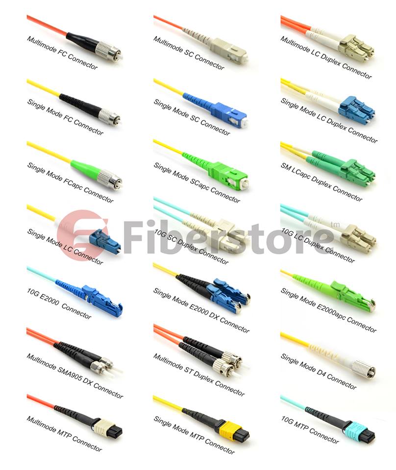
By connector construction standard, fiber optic patch cables include FC, SC, ST, LC, MTRJ, MPO, MU, SMA, FDDI, E2000, DIN4, and D4. Cables are classified by the connectors on either end of the cable; some of the most common cable configurations include FC-FC, FC-SC, FC-LC, FC-ST, SC-SC, and SC-ST.

LC-LC-single-mode-fiber-patch-

Fiberstore Solution

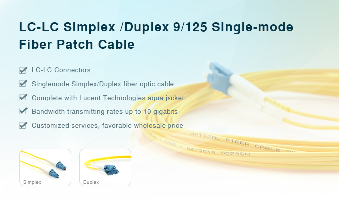
Fiber optic patch cables with high quality are characterized by low insertion loss, high return loss, good repeatability, good interchange, excellent environmental adaptability. Fiberstore can supply various types of fiber patch cables, including LC-LC Duplex 9/125 Single-mode Fiber Patch Cable and LC-LC Simplex 9/125 Single-mode Fiber Patch Cable. With LC to LC termination, complete with Lucent Technologies aqua jacket, bandwidth transmitting rates up to 10 gigabits, cost-effective solution that specifically designed for gigabit Ethernet applications, these fiber optic patch cables can provide 100% optically tested to ensure high performance. Fiberstore provides high standard and trusted quality, accurate return purchase and barter service, professional maintenance service to satisfy your requirements.

For more information about fiber optic patch cables, please visit Fiberstore.

Choose Fiber Patch Cable for Your Cisco Fiber Optic Transceivers

With the increasing demands of higher transmission, people may prefer fiber optic cables when considering network cabling. Compared to DAC, due to its flexibility, the fiber patch cable plays an important role in fiber optic data transmission, especially the data transmission between the switches and equipment, and now is widely used in both telecommunication and data communications. However, when choosing fiber patch cables for our transceiver modules, it seems to be a headache for many users on how to choose a right fiber patch cable. Today, I want to take the Cisco fiber optic transceiver module as an example to discuss this topic.

Actually, before starting this topic, it is necessary for us to review the basic knowledge of the fiber optic transceiver module and fiber patch cable.

Fiber Optic Transceiver Modules
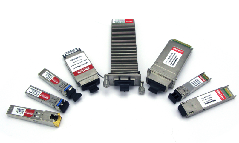
Fiber Optic Transceiver Module is a self-contained component that can both transmit and receive data signals. Usually, it is inserted in devices such as switches, routers or network interface cards which provide one or more transceiver module slot. The fiber optic transceivers here we mentioned include the SFP, SFP+ and X2 etc. Wanna review and get more details please visit What are the Differences between SFP, SFP+, XFP, QSFP/QSFP+, CFP and QSFP28?

transceiver module

Fiber Patch Cable
Fiber Patch Cable, also known as fiber optic cable or fiber optic patch cable is designed to interconnect or cross connect fiber networks within structured cabling systems. According to fiber cable mode, cable structure or connector types etc., fiber patch cable can be divided into different types.

fiber patch cable

Fiber Cable Mode – there are single mode fiber patch cable and multimode fiber patch cable. The word “mode” means the transmitting mode of the fiber optic light in the fiber optic cable core. Single mode patch cables are with 9/125 fiber glass and are yellow jacket color, while multimode patch cables are with OM1 62.5/125 or OM2 50/125 fiber glass and are in orange color. In addition, there is 10 Gigabit Laser Optimized OM3 and OM4 which cable jacket are usually aqua.

Fiber Cable Structure – simplex fiber patch cable consists of single fiber core, while duplex fiber patch cable consists of two fiber cores which are either multimode or singlemode. Additionally, there is also ribbon fan-out cable assembly (ie. one end is ribbon fiber with multi fibers and one ribbon fiber connector such as MTP connector (12 fibers), the other end is multi simplex fiber cables with connectors such as ST, SC, LC, etc.).

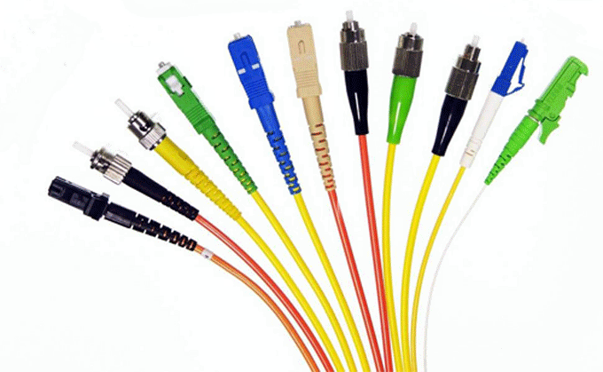
Connector Types – Fiber optic patch cable can be also classified by the types of fiber optic connector. For example, LC fiber optic patch cable is named as it is with LC connector. Similarly, there are SC, ST, FC, MT-RJ, E2000, MU and MPO/MTP fiber optic patch cables. What’s more, there are PC, UPC, APC type fiber patch cords, which are differentiated from the polish of fiber connectors.

connector types

How to Choose the Right Fiber Patch Cable for Your Cisco Fiber Optic Transceivers
We suppose that we need to choose a right patch cable using between Cisco fiber optic transceiver SFP-10G-SR and X2-10GB-SR. How should we do? According to “Cisco 10-Gigabit Ethernet Transceiver Modules Compatibility Matrix“, we may know that SFP-10G-SR is the 10GBASE-SR SFP+ transceiver module for MMF, 850-nm wavelength, LC duplex connector. And X2-10GB-SR is the 10GBASE-SR X2 transceiver module for MMF, 850-nm wavelength, SC duplex connector. Obviously, when we require X2-10GB-SR has SC connector, and the SFP-10G-SR has LC connector. so that we would require patch cable with SC-LC connector with MMF, 850-nm wavelength. In the same way, we could choose right fiber patch cable for your other transceiver modules. Of cause, if your transceiver modules are not Cisco’s, you need to ask your brand supplier to get the corresponding compatibility matrix.

FS Fiber Optic Transceivers & Fiber Patch Cable Solutions
FS provides various fiber patch cord types including single mode, multimode, multi core, and armored versions. You can also find fiber optic pigtails and other special patch cables here. For most of them, the SC, ST, FC, LC, MU, MTRJ, E2000, APC/UPC connectors are all available. Moreover, we supply MPO/MTP fiber cables.

FS provides a full range of optical transceivers, such as SFP+ (SFP Plus) transceiver, X2 transceiver, XENPAK transceiver, XFP transceiver, SFP (Mini GBIC) transceiver, GBIC transceiver, CWDM/DWDM transceiver, 40G QSFP+ & CFP, 3G-SDI video SFP, WDM Bi-Directional transceiver and PON transceiver. All our fiber transceivers are 100% compatible with well-known brands like Cisco, HP, Juniper, Nortel, Force10, D-link, 3Com. They are backed by a lifetime warranty. We also can customize optical transceivers to fit your specific requirements.

Related Articles: How to Select 10G SFP+ Modules for Cisco Switches?

                               Cisco SFP-10G-SR: All You Need to Know

Mode Conditioning Patch Cables in Gigabit Ethernet

Mode Conditioning Patch Cables in Gigabit Ethernet

Figure 1:Mode Conditioning Patch Cable

CAB-GELX-625=

IEEE 802.3z-compliant optical fiber assembly consisting of a single-mode fiber permanently coupled off-center to a 62.5-micron multimode optical fiber with duplex SC connectors at both ends. The patch cord is 3 meters (9.84 feet) in length.

CAB-MCP50-SC=

IEEE 802.3z-compliant optical fiber assembly consisting of a single-mode fiber permanently coupled off-center to a 50-micron multimode optical fiber with duplex SC connectors at both ends. The patch cord is 1 meter (3.28 feet) in length.

CAB-MCP-LC=
IEEE 802.3z-compliant optical fiber assembly consisting of a single-mode fiber permanently coupled off-center to a 62.5-micron multimode optical fiber with duplex SC connectors at one end and duplex LC connectors at the other end. The Mode Conditioning Patch cord is 1 meter (3.28 feet) in length.

Figure 1 shows an MCP and how it is typically connected to a transceiver module. When required, it is inserted between a transceiver module and the MMF cable plant.

Figure 2. Mode Conditioning Patch Cords Installation

MCPC