Category Archives: How To

How to Use Optical Power Meter

To ensure the signal transmission performance in fiber optic network, optical power should be well controlled. Optical power should not be too high or too low. And it should be within the scope of the device’s requirement. To achieve accurate measurement, optical power meter is usually used to test the optical power. But How to use optical power meter? This post will make an illustration of the power meter components and then state how to use optical power meter.

Buttons on Optical Power Meter

The functions and operation of optical power meters provided by the market are similar. Generally there are four buttons on the optical power meter: power button, dBm/w button, REF button and λ button. The functions of these buttons are listed in the following:

  • Power button: turn the power meter on or off;
  • dBm/w button: shift between linear (mW) mode and logarithmic (dBm) mode;
  • REF button: press this button to set the current measured power as the referent point;
  • λ button: select the calibrated wavelength. The most commonly used wavelengths are 850nm, 980nm, 1310nm, and 1550nm.

Here takes an example of a typical handheld optical power meter (FOPM-104) which is designed by FS.COM as shown in the following picture.how to use optical power meter: buttons

Adapter Type of Optical Power Meter

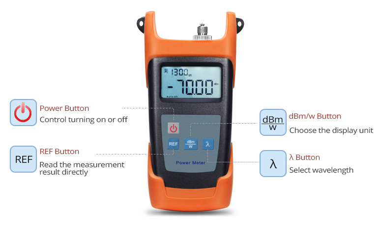
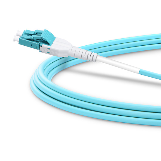
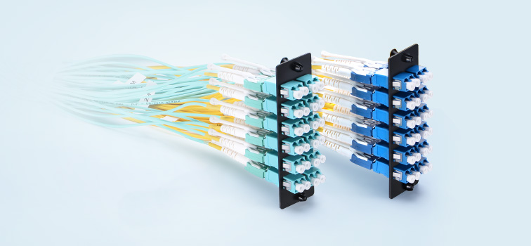
To use the optical power meter, a length of fiber optic patch cable is usually required to connect the optical power meter interface and the interface of devices requiring test. For instance, if the interface on the fiber optic power meter is FC, the device for testing has a LC interface. Then a length of FC-LC fiber patch cable is needed. Some of the optical power meters have only one fixed optical interface. Some can provide replaceable optical adapter to fit different patch cables. The above mentioned FOPM-104 handheld optical power meter provides three type adapters: SC, FC and ST (as shown in the following picture).optical power meter adapter

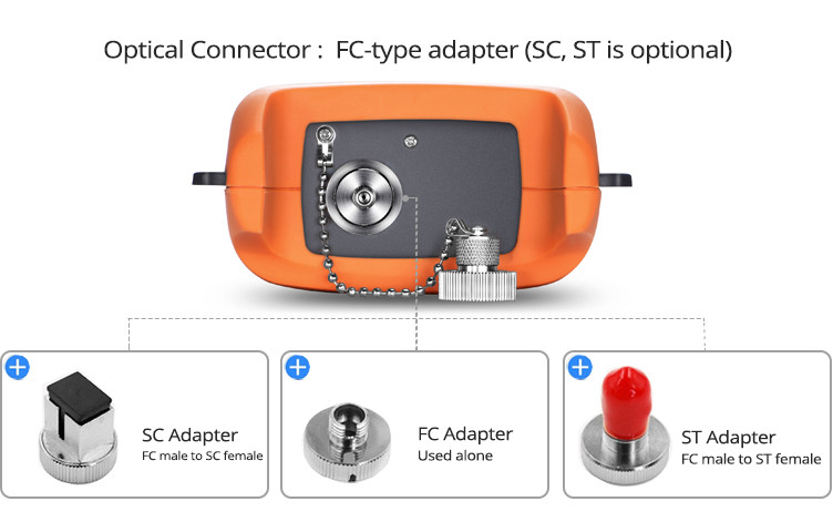
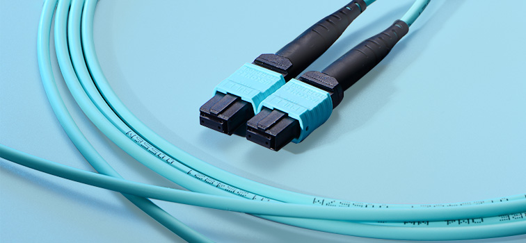
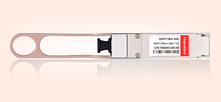
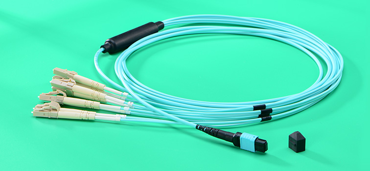
For testing of fiber optic interface like LC, SC, ST and FC, this above power meter is enough. Some optical power meter might have two optical interfaces for common connectors. However, interface like MTP/MPO, optical power meter with special interface should be used. The following picture shows a MTP optical power meter provided by FS.COM, which can be used to test devices or components with MTP interfaces like 40G SR4 QSFP+ transceiver.how to use optical power meter: adapter types

Optical Power Measurement Using Optical Power Meter

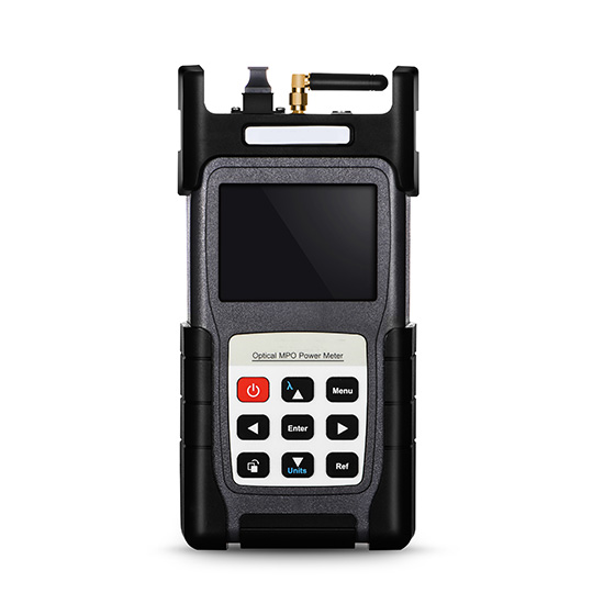
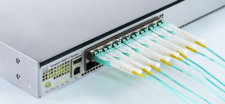
How to use optical power meter? It can be easy. The following video will take the example of 10G-LR SFP+ Cisco compatible module to illustrate how to use optical power meter for testing. This cisco compatible transceiver will be inserted in Cisco Nexus 9396PX switch. A length of single-mode LC-FC fiber patch cable is required. This is because 10G-LR SFP+ transceiver is a single-mode transceiver working on wavelength of 1310nm. After the optical power meter is connected to the module. Turn on the power button and press λ button to select 1310nm wavelength. At first the power value will change rapidly, then it slows down until still. The final power value will be shown on the screen.

Conclusion

This post introduces the buttons and adapter types of optical power meters, and illustrates how to use optical power meter with the aid of both text and video. Kindly visit Optical Power Meter page or contact sales@fs.com for more details.

Related Article: DWDM MUX/DEMUX Insertion Loss Test

                             Optical Power Meter (OPM): A Must for Fiber Cable Testing

How to Use OADM in WDM Network

Adding or Dropping signals of devices on the existing WDM network is very common to service providers. Adding a new fiber optic cable for signal transmission of the devices would cost too much. The using of OADM (Optical Add-Drop Multiplexer) solves this problem easily. A OADM can couple two or more wavelengths into a single fiber as well as the reverse process. Service providers can save a lot of money and installation time by adding OADM into the existing WDM network, if they want to add or drop signal on a single fiber.

WDM Solution

Types and Selection of OADM

OADM is generally deployed in WDM network which includes CWDM (coarse wavelength division multiplexing) and DWDM (dense wavelength division multiplexing). Thus, OADM can also be divided into CWDM OADM and DWDM OADM according to its applications. During the selection of OADM, the fiber count that a OADM should be considered. The most commonly used CWDM OADM can add or drop fiber count of 1, 2 and 4. For DWDM OADM, the fiber counts are usually 1, 2, 4 and 8. The installation environment should also be considered during the selection of OADM. There are mainly three types of OADM with different package form factors: plug-in module, pigtailed ABS box and rack mount chassis. The plug-in modules can be installed in empty rack enclosures. The following shows three CWDM OADM with different package form factor.

 4-channel OADM plug-in module  4-channel rack OADM  4-channel pigtailed oadm
Plug-in module OADM Rack mount OADM Pigtailed ABS box OADM
How to Connect OADM With WDM MUX/DEMUX

In most cases, OADM is deployed with CWDM or DWDM MUX/DEMUX. It is usually installed in a fiber optic link between two WDM MUX/DEMUXs. The following picture shows a CWDM network using a 1-channel dual fiber OADM between two CWDM MUX/DEMUXs. Signals over 1470 nm are required to be added to and dropped from the dual fiber link. On the OADM, there are usually one port for input and one port for output. The OADM can be regarded as a length of fiber cable in the fiber link. The point is the one or more strand of signals is added or dropped when the light goes through the OADM.

1-channel OADM

To better illustrate the using of OADM. Here takes the example of a 4-Channel CWDM OADM. This 4-channel OADM supports wavelengths of 1470nm, 1490nm, 1510nm and 1530nm. West port is connected to a CWDM MUX/DEMUX and the East port in connected to the other CWDM MUX/DEMUX on the other end of this fiber link. Up to 4 different wavelengths of optical signals can be added or dropped. The four Channel ports can be connected to the corresponding CWDM transceivers installed on switches. Then a CWDM fiber link with OADM is finished.

4-channel OADM

OADM Solution

OADM is a cost-effective and easy to use passive fiber optic component, which can provide easy to build and grow connectivity environment for WDM network. FS.COM provides full series of WDM MUX/DEMUX and CWDM OADM and DWDM OADM. Kindly contact sales@fs.com for more details.

Add More Beneficial to Fiber Patch Cables

More and more fiber optic cables are adding to the existing fiber optic network. Technicians are facing the challenges to detail with thousands or more fiber patch cables. Well organized fiber patch cable and fiber cabling system are no longer enough for the increasing need. The fiber patch cables used in data centers should still have reliable and stable performance under repeat connections and disconnections. To find the best solution for fiber patch cables in high density data center and server room. The most urgent current demands should be considered.

fiber cabling problems

How to Solve Fiber Cabling Problems

There are mainly two problems in data center for fiber cabling. One is too many fiber cables installed in limited spaces. The other one is the property of fiber optic cable which requires careful operation during cabling.

high density fiber cabling
Decrease Fiber Patch Cable Space Requirement With Uniboot Design

As more and more devices are added in data center, decrease fiber count in data center is not that easy. Thus, decrease the space requirement for each fiber optic patch cable is relatively easier. Decrease cable diameter is suggested. Smaller fiber cable diameter is preferred in data center now. New versions of duplex fiber patch cables like LC uniboot fiber patch cables are invented. The following picture shows one end of the LC uniboot fiber patch cable. This type of duplex fiber cable has a smaller cable diameter than that of traditional duplex zipcord fiber cable. And the uniboot design has lower space requirement for connector boot.

LC uniboot fiber patch cable
Provide Easier Finger Access With Push Pull Tab

However, even the sizes of the fiber cable and connector boot are decreased. The port type like LC, SC and MTP cannot be changed directly. There is still finger access problem at the device port is the devices like switches and fiber enclosure are fully loaded with fiber patch cables. Then a push pull tab is being added to the connector body. The following picture shows the details of LC uniboot fiber patch cable with push-pull tab.

LC push-pull fiber patch cable

With the help of this small but useful push-pull tab, data center technicians not only have easier access to every port, but also enjoy easier connecting and disconnecting of every individual fiber patch cable in high density cabling environment without affecting any other fiber links near it. There is also high density push-pull MTP-LC breakout cable available in FS.COM.

push-pull MTP-LC fiber patch cable
Use Bend Insensitive Fiber Cable for Flexible Cabling

Data center technicians are required to operate the fiber patch cables very carefully to decrease the bend loss. The using of bend insensitive fiber cable can offer a much flexible and easy cabling environment for the data center technicians. The worrying of bend loss can be eliminated.

bend insensitive fiber patch cable

All Benefits in One Fiber Patch Cable

As the above mentioned, to build a high density cabling environment, uniboot fiber patch cable and high density push-pull tab fiber patch cables are being invented. To offer an easier and flexible cabling environment with high performance, bend insensitive fiber cables are suggested. What if we add all these great advantages into a single length of fiber patch cable? Here introduces the very special but useful LC bend insensitive uniboot fiber patch cable with push-pull tab (shown in the following picture).

LC bend insensitive uniboot fiber patch cable

This LC uniboot fiber patch cable has all the above mentioned advantages for space saving, easy finger access and flexible cabling with lowest bend loss. These LC uniboot fiber patch cables of different fiber types and cable lengths are available in FS.COM. If you are looking for some fiber patch cables to add more beneficial to your data center, you can consider this LC Push-Pull bend insensitive uniboot fiber patch cable.

12-Fiber MTP Cabling System

MTP fiber cables and related components are now widely deployed in high speed fiber optic transmission system. MTP cables really provide great performance during 40G and 100G transmission over both short and long transmission distances. But there are so many types of MTP components like MTP cables, MTP cassettes, MTP adapters, MTP patch panels, etc. And all of these products are available in different MTP polarity types. Customers can get confused easily by these MTP products.

12-fiber MTP trunk cable

In addition, unlike traditional duplex transmission on two fibers or BiDi transmission over a single fiber, MTP system transmits optical signal over 12, 24 or more fibers at the same time. More fibers and cables are employed in MTP cabling system. Thus, technicians in data center or server room are still facing a headache problem which is MTP cable management. This post is to offer the details of a commonly used MTP cabling system—12-fiber MTP cable system for better understanding, selecting and management of MTP products.

12-Fiber MTP Cabling Applications

The 12-fiber MTP cabling system is usually used in the following standards: 40GBASE-SR4, 40GBASE-PLRL4, and 40GBASE-PLR4. 40GBASE-SR4 is used for 40G transmission in short distances up to 150 meters over OM4 fibers. 40GBASE-PLRL4 and 40GBASE-PLR4 support transmission distance over single-mode fiber up to 1.4km and 10km separately. These standards use 40G parallel transceivers with 12-fiber MTP interfaces.

40G-SR4-QSFP+

Except 40G transceivers with 12-fiber MTP interfaces, there is a wide range of 12-fiber MTP connectivity components for transmission. These MTP cabling products cable be used in a lot of applications.

12-Fiber MTP Cabling Connectivity Components

12-Fiber MTP Trunk Cable: MTP trunk cable can be regarded as MTP to MTP fiber patch cable. MTP trunk cable is terminated with MTP connectors on both ends. The MTP connectors can be male (with guide pin on the contact interface) or female (without guide pin). As above mentioned, MTP cables can be divided into different types: Polarity A, Polarity B and Polarity C. A previous of my article “Understanding Polarity in MPO System” has introduced the polarity of MTP components. You can follow this article about the MTP polarity details.

The most commonly used MTP trunk cable is a single strand of cable, which can provide duplex 40G transmission at the same time. There are also MTP trunk cables which are composed by several strands of cables. Take the example of 12-fiber MTP trunk cables as shown in the following picture. On the left of this picture, there is a 12-fiber MTP trunk cable which is a single strand cable. On the right of this picture, there is a 72-fiber MTP trunk cable which is composed by 6 strands of 12-fiber MTP trunk cable.

12-fiber MTP trunk cable

12-Fiber MTP Harness Cable: MTP harness cable is a length of fanout cable with one end terminated with MTP connector and the other end terminated with several connectors like LC and SC. 12-fiber MTP harness cables also come in a variety of types according to fiber type, polarity type and connector types. The following picture shows a most commonly used MTP-4 duplex LC fiber cable.

MTP-8LC harness fiber cable

12-Fiber MTP Cassette: MTP cassette is like MTP harness cable which also provides the transferring between MTP interface and LC or SC interfaces. But MTP cassette can protect the fragile optical fibers inside the metal box, and has lower space requirements than MTP harness cable. The following picture shows a 12-fiber MTP-LC Cassette.

12-FIber MTP-LC Cassette

Typical 12-Fiber MTP Cabling Guide

The 12-Fiber MTP fiber optic products can be used in many situations not only for 40G fiber network. The following introduces several typical fiber cabling solutions using 12-fiber MTP products.

12-Fiber MTP Products in 10G to 10G Transmission

The following picture shows the wire guide for 10G to 10G connections using OM3 12-fiber MTP fiber cables and 12-fiber MTP-LC cassettes. A 10G link just uses two of the 12 fibers. On each end of this link, up to six 10GBASE-SR SFP+ modules can be connected to the fiber optic network, which means up to 60G can be transmitted by the following 12-fiber MTP system.

10G MTP fiber cabling

12-Fiber MTP Products in 40G to 40G Transmission

For 40G to 40G transmission, MTP trunk cable is usually being used. The following picture shows the connection of two brocade ICX 7750 switches over long transmission distance. Brocade compatible QSFP-PLR4-40G transceivers are being used on both ends of this 40G fiber link. 12-fiber MTP OS2 trunk cable is being used to connect the QSFP+ modules on each end.

40G-QSFP-PLR4 Cabling

    Items required in this 40G to 40G fiber optic link

  • QSFP-PLR4-40G QSFP+
  • OS2 12-Fiber MTP Trunk Cable

12-Fiber MTP products in 40G to 10G Transmission

Sometime the 40G device is still required to be connected with 10G devices. Here takes the example of connection between 40G QSFP+ port on Brocade 7750 and 10G SFP+ port on Brocade Fastlron FCX6245 over long transmission distances. To distribute the 40G signals into four 10G, Brocade compatible QSFP-PLR4-40G transceiver, and Brocade compatible 10G-LR SFP+ transceiver, 12-fiber MTP-LC cassette, 12-fiber MTP trunk cable and four LC-LC duplex single-mode fiber patch cables are used. The MTP cassette transmitting the MTP interface to the LC interfaces as shown in the following picture.

40G-PLR4 cabling

    Items required in this 40G to 10G fiber optic link

  • QSFP-PLR4-40G QSFP+
  • OS2 12-Fiber MTP Trunk Cable
  • OS2 12-Fiber MTP-LC Cassette
  • OS2 LC-LC Fiber Patch Cable
  • 10G-LR SFP+
Conclusion

12-fiber MTP cabling system is a cost-effective and space saving solution for both 10G and 40G transmission. As most of the MTP fiber products are factory pre-terminated, these products can provide fast installation and great network performance. FS.COM provides full range of MTP fiber optic products. You can visit FS.COM or contact sales@fs.com for more details about MTP fiber cabling.

Which Armored Fiber Cable Should I Choose?

Armored fiber cable with build-in metal armor can provide stronger protection of the optical fibers than standards fiber optic cables. It can protect the optical fibers from rodent, oil, impact, etc. What’s more, some armored fiber can provide maximum bend radius. However, various types of armored fiber cables usually make customers confused. There are too many specific details to consider during selection, like fiber counts, jacket type, structure of the armored fiber cable, etc. This post is offering the details about how to select the right armored fiber cable.

outdoor armored fiber cable

Structure and Application of Armored Fiber Cable

Structures of armored fiber optic cables come in a variety of types according to different applications. There are mainly three types of armored fiber cable: indoor armored fiber cable, outdoor armored fiber cable and indoor/outdoor armored fiber cable. Each of the three armored fiber cables has various subcategories. The structures of the three types of armored fiber optic cable are different from each other. Here takes the example of an indoor light armored fiber cable to introduce the basic structure of armored fiber cables.

armored fiber cable structure

As shown in the above picture, the optical fibers of the armored fiber cable are in the center of the cable covered by metal armor. The metal armor is covered by Kevlar firstly, then by the outer jacket. This is usually the most basic structure of armored fiber cables. For different applications, the structure will change accordingly. Watch the video below to get more details about the basic structure of armored fiber cable and where they are used.

How to Select Armored Fiber Cable?

The selecting of armored fiber optic cable is like the selection of standard fiber cables. Fiber type (OS2, OM1, OM2, OM3, or OM4), fiber count and cable riser should all be considered. However, there is many special properties of armored fiber optic cable, the armored fiber cable selection should also consider many other factors.

interlock armor and corrugated armor
Armor Type of Armored Fiber Cables

The market can provide armored fiber cables with different types of armor tubes which are with different structures and materials. The most commonly used armor tubes are with interlock design and corrugated design as shown in the above picture. For now, the interlock armored fiber cable is very popular and being used in a lot of indoor and indoor/outdoor applications. Corrugated armored fiber cable is often used in outdoor applications. As for the materiel for armor tube, steel and aluminum are the most commonly used. Now light steel armored fiber cables are being widely used in a lot of indoor applications, because of its lower weight and flexible properties.

pre-terminated armored fiber cable
Pre-Terminated or Field-Terminated Armored Fiber Cables

As there is a strong metal armored tube inside the armored fiber cable, the termination of armored fiber cable is difficult than that of standard fiber optic cables. In some applications, field-terminated armored fiber cable is better in outdoor applications. While, to save time and ensure transmission quality, many installers will choose pre-terminated armored fiber cables for indoor applications. The pre-terminated armored fiber cables provided by the market are mainly armored fiber patch cable and armored fiber trunk cable. The former looks like the standard fiber patch cable, but it is stronger than the traditional fiber patch cable and is more flexible during cable for it can provide larger bend radius. Pre-terminated armored fiber trunk cable is a length of armored fiber cable with several legs on each ends terminated with fiber optic connectors.

Conclusion

Armored fiber cable is a cost-effective solution for fiber optic link protection. During the selection of the armored fiber cable, except fiber count, fiber type and cable riser, the armored type, cable structure and termination types should also be considered. If you are looking for more information about fiber cable for harsh cabling environment, you can visit another article: Fiber Patch Cables for Harsh Environment.

Related Article: What is Armored Fiber Cable?