Category Archives: Network Solutions

What Cable Should I Use for 10G Transceiver Module?

To deploy the optical network, the transceiver module and patch cable are the two basic components. According to the feedbacks of customers from FS.COM, one of the common problems faced by them is what cables they should use for their transceiver modules. To solve this problem, we make this post of patch cable selection guidance. Since the order for 10G transceivers ranks top, we are going to take 10G modules as a reference.

An Overview of 10G Transceiver Module

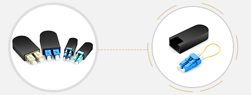
Transceiver module, also called fiber optic transceiver, is a hot-pluggable device that can both transmit and receive data. By combining a transmitter and receiver into a single module, the device converts electrical signals into optical signals to allow these signals to be efficiently transferred on fiber optic cables. As for the 10G transceiver, it refers to the optical modules with 10G data rate. In FS.COM, there are mainly four types of 10G transceivers: XENPAK, X2, XFP, and SFP+. Even though these optical transceivers are all accessible to the 10G networks, they have different matching patch cables and applications.

10G Transceiver Module

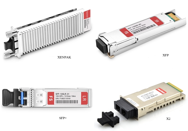
Figure 1: 10G Transceiver Modules

Patch Cable Basics

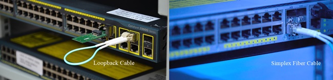
Apart from optical module, the patch cable is the other vital role in networking. Patch cable, also called patch cord, refers to the copper or optical cable. It’s designed to connect one electronic or optical device to another for signal routing. Conventionally, the patch cable will be terminated with connectors at both ends. For example, the LC fiber cable refers to the optical cable fixed with LC connector. Typically, there are LC, SC, ST, FC and MTP/MPO fiber patch cables. According to different features, we can get various classifications of patch cables, such as fiber types, polishing types, etc.

Patch Cables

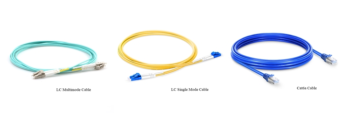
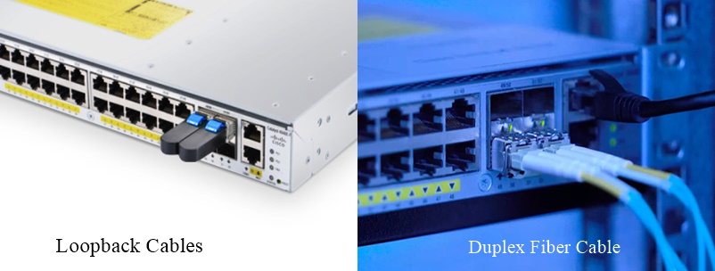
Figure 2: Patch Cables

Factors to Consider When Choosing Patch Cable for 10G Transceiver Module

Recently, most of the 10G transceiver modules are compatible with different brands and support higher data rates. It will be much easier to choose optical modules for your networking than selecting mating patch cables. Based on most applications, there are three major factors that can be taken into consideration: transmission media, transmission distance, and transceiver module interface.

Transmission Media

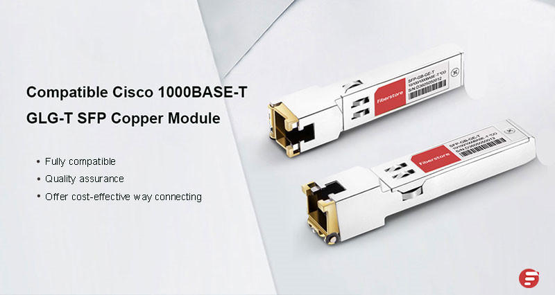
Classified by transmission media, two types of patch cables can be found in the market: optic fiber cable and copper cable. Correspondingly, there are two kinds of optical transceivers available: copper-based transceivers and fiber optic based transceivers. Copper transceiver modules like 10GBASE-T SFP+, they have an RJ45 interface, connecting with copper cables. Typically, Ethernet cables that support 10G copper-based transceivers are Cat7 and Cat6a cables.

As for the 10G optical modules, they can support higher data rates over optic fiber cables. It will be more complicated to choose fiber cables. Generally, there are multimode fibers and single mode fibers. Based on the specified needs for transmission distance, the answer will be varied.

Transmission Distance

To select cables, the transmission distance is also an important factor that you need to take care. In the following table, we list the basic information of common 10G transceivers, including their supporting fiber cable types and transmitting distance.

Transceiver Type
Wavelength
Cable Type
Transmission Distance
SR
850 nm
MMF
300 m
LR
1310 nm
SMF
10 km
ER
1550 nm
SMF
40 km
ZR
1550 nm
SMF
80 km

As for fiber cables, single mode fiber is used for long-distance transmission and multimode fiber is for short distance. In a 10G network, the transmission distance of single mode fiber (OS2) can reach from 2 km to 100 km. When it comes to multimode fibers, the transmission distances for OM1, OM2, OM3 are 36 m, 86 m and 300 m. OM4 and OM5 can reach up to 550 m.

Transceiver Module Interface

Another factor you need to consider is the transceiver interface. Usually, transceivers use one port for transmitting and the other port for receiving. They tend to employ duplex SC or LC interface. However, for 10G BiDi transceivers, it only has one port for both transmitting and receiving. Simplex patch cord is applied to connect the 10G BiDi transceiver.

Summary

For your 10G network cabling, transceiver module and patch cable are necessary components. With a wide range of patch cables, selecting the right patch cables will be more complex than 10G transceivers. Generally, three major factors can be considered: transmission media, transmission distance, and transceiver module interface. To apply what you have learned in this post in cabling, you can visit FS.COM for all the transceivers and patch cables at one shop.

How to Troubleshoot Transceiver and Switch Port Through Loopback Test?

Loopback

Loopback is a commonly used term in telecommunications. It refers to the process of transmitting electronic signals or digital data streams and returning to their sending point without any intentional processing or modification. Therefore, by comparing transmitting signals with the receiving signals, the loopback test is used to debug physical connection problems. But what a loopback test means for fiber optic network and how to make use of it will be the issues that we will explore in this post.

Why Need Fiber Loopback Test?

To conduct a fiber loopback test, the communication devices will be involved, like the transceivers and the switch. As you know, the transceiver is the basic component of fiber optic communication network equipment. We can take the transceiver as a case. Conventionally, a transceiver has a transmitting port and a receiving port, in that way, the loopback test can be applied to test the ports to diagnose whether the transceiver is working well and the configuration of the switch is right. For its unique working mode, the test is a convenient way to maintain transceivers. In the next part, we will deliver how to do the fiber loopback test on the transceiver.

How to Conduct Loopback Test?

In this part, we will introduce two types of tests to troubleshoot transceiver and switch port: single-port test and dual-port test.

Tools You Need to Prepare

To perform tests, things you need to prepare are listed below:

  • Transceivers (2pcs), such as 10G SFP+ SR transceiver.
  • Simplex fiber cable (1 pc).
  • Switch (1 pc), like Cisco switch.
  • Duplex fiber cable (1 pc).
  • Two loopback cables (optional), like LC or SC loopback cable. To know more about loopback cable, you can move to the article: What Is Loopback Cable And How to Use It?
Loopback Cable

Figure 1: Loopback Cable

Loopback Test Steps
Single-port Loopback Test

Figure 2: Single-port Loopback Test

1. Connect your transceiver with one simplex fiber cable or loopback cable, such as LC fiber cable or LC loopback cable. At this step, you can examine whether the port and transceiver parameters are normal.

2. Check the software version of the switch.

3. Review the interfaces status to confirm the working status of all ports on the switch.

Display the Working Status of All Ports

Figure 3: Display the Working Status of All Ports

4. Check the working status of the port you are connecting, such as the port 50 in the following figure.

Working Status of Interface 50

Figure 4: Working Status of Interface 50

5. Go over the DDM information to review whether the transceiver works in normal status.

DDM Information of Port 50

Figure 5: DDM Information of Port 50

Dual-port Loopback Test

Figure 6: Dual-port Loopback Test

1. Connect two transceivers with one duplex fiber cable or two loopback cables. At this step, you can examine whether the port and transceiver data rate are matching as well as the link is normal or not.

2. Check the interfaces status to confirm the working status of all ports on the switch.

Ports Working Status Display

Figure 7: Ports Working Status Display

3. Check the working status of the two ports you are connecting, such as the ports 50 and 52 in the following figure.

Working Status of Interfaces 50 and 52

Figure 8: Working Status of Interfaces 50 and 52

4. Go over the DDM information to review whether the transceiver works in normal status.

DDM Information of Ports 50 and 52

Figure 9: DDM Information of Ports 50 and 52

Summary

To troubleshoot the circuit connectivity as well as the transceiver and the switch port, loopback test is a cost-effective way. In this post, we have an overview of loopback and make a demonstration of how to conduct the loopback test on a switch to debug the transceiver and the switch port.

FMT 4000E for DWDM Network Solution

In the network era, the demand for greater traffic capacity, higher bandwidth, and better performance over longer transmission distance has never stopped. Under such a context, the optic transport network (OTN) has undergone great changes to survive. At the moment, FS provides its all-in-one dense wavelength division multiplexing (DWDM) OTN solutions. In this post, we will share one of the most popular DWDM solutions: FMT 4000E.

DWDM Network Basics

DWDM

Dense wavelength division multiplexing is a technology based on wavelength-division multiplexing (WDM). It combines or multiplexes data signals from different sources for transmissions over a single fiber optic cable. At the same time, data streams are completely separated. Each signal is carried on a separate light wavelength. In most cases, the dense wavelength division multiplexing technology is applied in metropolitan network.

Optical Transport Network

Defined by the ITU Telecommunication Standardization Sector (ITU-T), OTN is a set of optical network elements (ONE) that are connected by optical fiber links. Sometimes, it’s also called the digital wrapper technology which provides an efficient and globally accepted way to multiplex different services onto optical light paths. This technology provides support for optical networking by using WDM unlike its predecessor SONET/SDH. It’s able to create a transparent, hierarchical network designed for use on both WDM and time-division multiplexing (TDM) devices. The OTN is able to support functions, like transport, multiplexing, switching, management, supervision, and builds OTN client (e.g. SONET/SDH, IP, ATM) connections in the Metro and Core networks.

Optical Transport Network

Figure 1: Optical Transport Network

DWDM Network

The DWDM based network refers to a kind of dense wavelength division multiplexing technology-based OTN solution. Compared with CWDM, the DWDM uses more sophisticated electronics and photonics, which makes its transmitting channel are narrower than CWDM channels. Therefore, for a DWDM network, it can support more channels and separate wavelengths (up to 80 wavelengths). It can transmit data in IP, ATM, SONET, SDH, and Ethernet. For its protocol and bitrate independence, the DWDM-based OTN networks can carry different types of traffic at different speeds over an optical channel.

DWDM vs CWDM Wavelength

Figure 2: DWDM vs CWDM Wavelength

FMT 4000E for DWDM Solution

In order to make the DWDM OTN deployment easier, FS has launched the high integration FMT WDM transport networks, such as FMT 1800 and FMT 9600E. In this post, we will mainly introduce the most popular solution: FMT 4000E.

What Is FMT 4000E

The FMT 4000E is a device that combines the OTN switching and dense wavelength division multiplexing features and provides unified transmission of all services. It integrates DWDM equipment with OTN function cards (EDFA, DCM, OEO) in a 4U form factor. With FMT 4000E, you can extend the optical link power budget for building long-distance dense wavelength division multiplexing solutions.

FMS 4000E

Figure 3: FMT 4000E

Strengths of FMT 4000E
  • Supports up to 40 wavelengths via the dual fiber bi-directional transmission mode.
  • Transmits up to 100 km with DWDM SFP+ 80km at the rate of 10Gbps.
  • Optional function cards to meet various needs (WDM Mux/Demux, EDFA, DCM, OEO).
  • Dual AC or DC pluggable power supply and fan unit.
  • Supports SDH/SONET, PDH, Ethernet, SAN, LAN, video service transport.
  • Scales easily for the ring, end to end and mesh networks.
  • Suitable for the enterprise, medical, Storage Area Networks (SANs), data centers, campus optical network and video surveillance.
  • Scalable solution for customers to expand capacity as needed. And operating costs and vital resources are greatly saved.
  • Ensure the maximum bandwidth for the required capacity and transmission distances.
  • Fully managed, configured and monitored remotely via FS.COM intelligent network management unit.
  • Simple installation, operation, and maintenance.
  • Standards-based and can integrate with third-party solutions.
  • The solution can be customized to suit specified customer application requirements.
Solution Topology
FMS 4000E Solution Topology

Figure 4: FMT 4000E Solution Topology

Note: This solution does not come with OPM, OPD, OLP, OSW card.

Matching Products
  • 40CH C21-C60 DWDM Mux Card ( 2pcs)
  • 40CH C21-C60 DWDM Demux Card ( 2pcs)
  • 20dB Gain Pre-Amplifier DWDM EDFA Card (2pcs)
  • 17dB Output Booster EDFA Card (2pcs)
  • 40km Passive Dispersion Compensation Card (4pcs)
  • FMT 4U Managed Chassis (2pcs)
  • LC/UPC Single Mode Fixed Fiber Optic Attenuator, 3dB (1pc)

Summary

Obsessed with higher bandwidth applications and the simplest operation, the OTN has broken through its traditional operation and make inroads into the highly integrated OTN. Undoubtedly, the DWDM solution will be the one having the last laugh after networking ups and downs. To share that last laugh, FS provides its DWDM solutions for multi-service optical transport over ultra-long distance: FS WDM Multi-service Transport (FMT) series. They help our customers to build an access transport network with more flexible service access, easier operation and lower OPEX.

Cisco Transceiver Module: GLC-T vs GLC-TE

Cisco SFP transceiver modules have become exceedingly popular with the widespread of Cisco routers and switches. GLC-T and GLC-TE are the two types of Cisco SFP transceiver module. Since the name GLC-T and GLC-TE are quite similar, many end users may be confused. So are they the same one? Here we’ll focus on GLC-T vs GLC-TE to help find the answer.

<p style="text-align: justify;">

GLC-T Datasheet

Cisco GLC-T SFP is a 1000BASE-T Small Form-Factor Pluggable RJ45 interface converter. It can be inserted into Gigabit Ethernet ports to connect ports to the network. GLC-T SFP transceiver provides 1Gbps data transmission. Besides, it supports the full-duplex Gigabit Ethernet connection for the high-end workstation. Operating on CAT5 cables, this SFP transceiver is designed with the max cable distance up to 100 meters. However, GLC-T has not been on sale since June 1, 2017. The following is the GLC-T datasheet.

Description
1000BASE-T SFP transceiver for CAT5 wire, RJ 45 connector
Max Data Rate
1000Mbps
Max Distance
100m
Operating Temperature
0 to 70°C (32 to 158°F)
Commercial Availability
Announced EOS by Cisco and has not been available for sale since June 1, 2011

GLC-TE Datasheet

GLC-TE transceiver is also a Cisco SFP module that designed for Gigabit Ethernet applications. It’s compatible with the IEEE802.3 1000BASE-T standard. It’s the replacement model of GLC-T, which means GLC-TE is an improved technology product. Therefore, this transceiver is designed with the same features of GLC-T type, but has an extended temperature range from -5 to 85°. GLC-TE is the latest in technology and definitely will continue to be sold for years. The table below shows GLC-TE datasheet.GLC-TE Datasheet

Description
1000BASE-T SFP transceiver for CAT5 wire, RJ 45 connector, extended temperature
Max Data Rate
1000Mbps
Max Distance
100m
Operating Temperature
-5 to 85° (23 to 185°F)
Commercial Availability
New product and will continue to be sold for years.

GLC-T vs GLC-TE: Difference and Similarity

  • Difference. From the above, we can clearly know that the main difference between GLC-T vs GLC-TE is the operating temperature. This means GLC-TE can work in a lower or higher temperature environment without any damage.
  • Similarity. Both GLC-T and GLC-TE are 1000BASE-T copper transceivers that comply with IEEE 802.3 standard. They support the same data transmission speed and cable distance via CAT5 copper cables. However, considering that GLC-T SFP transceiver has stopped production, GLC-TE is the best choice.

In addition, as for GLC-T vs GLC-TE, there are many similarities except for operating temperature. The two SFP transceivers can be used in the following cabling system.

glc-t vs glc-te cabling

All the networking equipment is produced by FS.COM. They are:

Item NO.
ID
Description
Cisco GLC-T Compatible 1000BASE-T SFP Copper RJ-45 100m
3.3ft (1m) Cat6 Snagless Unshielded (UTP) PVC Ethernet Network Patch Cable, Gray
24 Ports Cat6 Feed-Through Patch Panel, UTP Unshielded, 1U Rack Mount
3m (10ft) 6 Plug to 6 Plug Cat6 Unshielded PVC CMR (Blue) Pre-Terminated Copper Trunk
S5800-48F4S (48*1GE+4*10GE) High Performance Data Center Switch
Generic Compatible 1000BASE-T SFP Copper RJ-45 100m

Conclusion

As for GLC-T vs GLC-TE, we have found the difference and similarity. Both GLC-T and GLC-TE SFP transceivers are widely used because they are convenient and cost effective means for adopting Gigabit Ethernet in a myriad of industries and sectors. As a reliable and qualified networking solution supplier, FS.COM provides a full line of networking equipment like transceivers, switches etc. For further information, please visit FS.COM.

What Is a KVM Switch and How Does It Work?

Today, data centers and companies have to deal with the space limitation of lots of computers. They need a method to control the increasing numbers of computers and other networking devices efficiently. KVM switches are invented to combat this issue that is taking up valuable space and time. So what is a KVM switch and how does it work?

what is a KVM switch

Figure: KVM switch is widely used in our life.

What Is a KVM Switch?

What is KVM? KVM stands for keyboard, video and mouse. And as for what is a KVM switch, it’s technically “keyboard, video and mouse switch”. KVM switch is a hardware device that allows users to control different computers through one set of keyboard, video monitor and mouse. This is the KVM over IP solution, which is very useful if the server settings are located off-site and you don’t want to drive over there each time when you need to make changes. The switches will be assigned an IP address and accessed from any place in the world with the right username and password.

In addition, we should note that, although KVM switch and Gigabit Ethernet switch both can control multiple computers or servers, they are different devices. KVM switch is usually considered as a hardware device, which is popular when people have upgraded their computer systems or add new computers but don’t want to invest in a second keyboard, display and mouse. While Ethernet switch is regarded as a central hub. Commonly, it’s connected to each computer or network device in an Ethernet. Therefore, they are two different devices with different functions.

How Does KVM Switch Work?

We have a good understanding of the question what is a KVM switch. It can control more than two or greater numbers of computers(over 500). Users can use Cat5 cables or the specific KVM cable kits to connect the computers to the KVM switch. Then, connect the keyboard, display and mouse console to the KVM switch. If the switch is equipped with the console, this step could be skipped. Now users can use a button, on-screen display controls or hot keys on the keyboard to switch from one computer to another.

Which Type of KVM Switch Do I Need?

Designed for various end-user needs, there is a considerable choice of KVM switches on the market. Before buying, you should consider:

  • How many computers do I need to control?
  • What type of KVM switch do I require?
  • Do I need an on-screen display?

Use the table below to help you make a suitable decision.

FS ID
Server Port
8 × HDB-15 Female
16 × RJ45 port
8 × RJ45 port
Console Port
USB/PS2, VGA
USB, VGA
USB/PS2, VGA
On-screen Display
Yes
Yes
No

All these KVM switches are made by FS.COM, which can be accessed from any computer on the LAN, WAN or Internet. With easy installation and use, they’re the optimal solutions for controlling up to 8 or 16 computers or servers.

Conclusion

What is a KVM switch? It’s an ideal tool for saving time and energy when lots of computers or servers are involved. To find out more about our KVM switches with high performance, as well as other networking options like 10Gb Ethernet switch, patch panels, please visit FS.COM.