Category Archives: Network Solutions

Differences Between Fiber Latency and Copper Latency?

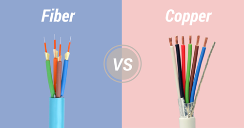
Fiber optic communication has developed rapidly in recent years. And in many applications, fiber optic cable has replaced the copper cable for higher speed and higher bandwidth applications. Therefore, numbers of people claim that fiber optic lines have lower latency than copper connections, while others do not think so. Then what’s the latency differences between fiber and copper?

fiber-vs-copper latency

Latency in Fiber and Copper

Latency refers to a time delay between stimulation and its response. Usually, it’s caused by velocity limitations in a physical system. Put it in simple terms, latency is the time it takes for a signal to travel from one place to another place. And there are diverse types of latency: network latency, Internet latency, audio latency, WAN latency, etc. No matter in a fiber optic network or a copper network, latency can be described as distance and speed. In addition, latency does exist. It’s just a question of fast or slow. One key factor that affects the latency is the signal speed in transmission media. Fiber and copper are two of transmission media. The type of media used in the communication system depends on the bandwidth and transmission distance required by the application.

Fiber Latency

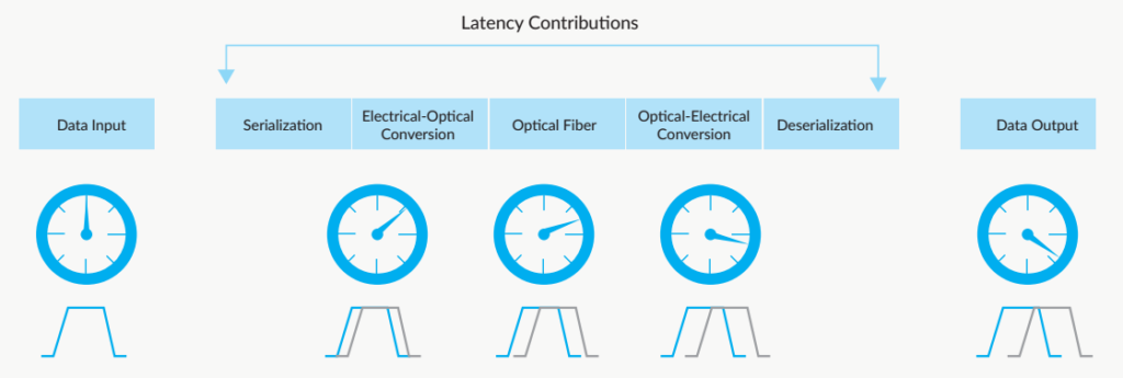
As we know, the speed of light in free space is about 3×10meter per second. While the speed of light in air is slower than that in a vacuum. So does in the glass. Therefore, when an optical signal travels in a fiber link, there are five latency contributors: two are created when the signal moves from the electrical domain to the optical; another contribution occurs as the signal goes through the optical fiber; and as the signal is converted from the optical domain to the electrical, latency occurs.

fiber latency

Copper Latency

Signals in copper cables are easy to be interrupted by around environments, especially in long distance transmission. The signals will attenuate as distance increases, which will lead to data transmission error, page error and make users feel slow speed at the moment. Actually, the copper cable transmission speed doesn’t slow down. Besides, alien crosstalk also would cause transmission errors and latency.

copper latency

Fiber vs Copper: What’s the Latency Difference?

Signals are transmitted at 2/3 the speed of light in fiber optic cables. In copper it can be faster than that. However, this cannot account for system latency. In longer distance, latency in the fiber optic system is lower because of less need for processing and repeating of the signals. While signals in copper are affected by electromagnetic interference and are prone to higher rates of loss over long distances.

In addition, no mater in a fiber optic network or a copper network, latency can be described as distance and speed. In addition, during the whole transmission process, serialization delay that shows how fast a data packet can be serialized onto the wire, has far more impact on shorter distances. For example, it will take 8ms to serialize a 1500-byte packet on 1.5Mbps link, while it will only need 1.2us on 10Gbps or less on higher speed. That shows speed makes a significant difference.

Summary

In a word, the latency differences between fiber and copper are influenced by transmission distance, speed, and environments. For shorter distance, copper cables can be the first choices, for the delay in it does not mean much and its low cost. For longer distance transmission, fiber cable offers lower latency for the whole network and can be an optimal choice.

Related Articles: What Is Copper Trunk Cable and How to Use It?
Fiber Optic Cable vs Twisted Pair Cable vs Coaxial Cable

Compatible SFP Modules for Mikrotik CRS125-24G-1S-IN & CRS125-24G-1S-RM

Mikrotik CRS125-24G-1S series cloud router switch is available in Mikrotik CRS125-24G-1S-IN and Mikrotik CRS125-24G-1S-RM two models. It combines the best features of a fully functional router and a layer 3 switch, is powered by the familiar RouterOS. As we know, these two models switch both have one SFP port. Then, what SFP module can you choose for your switch? This blog will give some choices.

Overview for CRS125-24G-1S-IN and CRS125-24G-1S-RM Switch
As show in the figure below, both Mikrotik CRS125-24G-1S-IN and Mikrotik CRS125-24G-1S-RM switches have 24 RJ45 ports and 1 SFP port. One is a desktop type, and the other is a 1U rack mount type. You can according to your specific needs to choose the right one.

CRS125-24G-1S-IN CRS125-24G-1S-RM

Detailed specifications for CRS125-24G-1S and CRS125-24G-1S-RM are listed in the following table:

CPU Qualcomm Atheros AR9344 600 MHz
Memory 128MB
Ethernet 24x 10/100/1000 Mbit/s Gigabit Ethernet with Auto-MDI/X
Expansion microUSB port
Storage 128MB Onboard NAND with multiple OS partition support
Serial port One RJ45 serial port
Extras Reset switch; beeper; voltage and temperature monitoring, touchscreen LCD
Power options 8-28V, 24V 0.8A PSU included
Case dimensions 285x145x45mm
Temperature -35C to +65C tested
OS MikroTik RouterOS v6, Level 5 license
Included CRS switch, power adapter, and USB OTG cable (for 4G dongle or USB drive)

User Guide for CRS125-24G-1S-IN and CRS125-24G-1S-RM Switch
The CRS125-24G-1S and CRS125-24G-1S-RM are pre-installed with RouterOS and are ready to use. Switch is compatible with RouterOS v6 and newer, if your switch comes pre-installed with an earlier version, please upgrade before using it. For CRS125-24G-1S and CRS125-24G-1S-RM: All the ports are switched. Both models can be accessed though the IP 192.168.88.1, username is admin and there is no password. Please connect with your web browser to this IP address to configure it.

Compatible SFP Modules for CRS125-24G-1S-IN & CRS125-24G-1S-RM Switch
According to Mikrotik cloud router switch guide, CRS125-24G-1S-IN and CRS125-24G-1S-RM switches are compatible with 1.25G SFP modules. SFP+ port supports only modules up to 10KM LR (long reach). FS.COM provides a full range of compatible 1.25G SFP modules at high quality and low price, which can work well in Mikrotik switches. 1000BASE-SX SFP modules are only sold at US$  6.00. Part of the products from FS that are compatible with this Mikrotik CRS125-24G-1S-IN and CRS125-24G-1S-RM switches are listed below for your reference.

FS P/N Description
SFP-GB-GE-T Generic Compatible 1000BASE-T SFP Copper RJ-45 100m Transceiver
SFP-GB-GE-T Generic Compatible 10/100/1000BASE-T SFP Copper RJ-45 100m Transceiver
SFP1G-SX-85 Generic Compatible 1000BASE-SX SFP 850nm 550m DOM Transceiver
SFP1G-SX-31 Generic Compatible 1000BASE-SX SFP 1310nm 2km DOM Transceiver
SFP-LX Generic Compatible 1000BASE-LX/LH SFP 1310nm 10km DOM Transceiver

Related Article: Mikrotik CRS317-1G-16S+RM Transceiver/DAC Cable Solution

Can A Computer Connected to the PoE Switch?

The PoE switch is commonly used in various networks. It can be low-cost unmanaged edge switches with a few ports or complex multi-port rack-mounted units with sophisticated management. When used in small or home networks, many people may wonder if it can be connected directly with a computer. This post will discuss how to build a PoE connection between the PoE switch and the computer.

What Are PoE and PoE Switch

Before the discussion, it is necessary to have a basic understand of what are PoE and PoE network switch:

PoE

As demands for connection from networking devices such as IP phones, IP cameras and access points increase, deployment complexity and cost rise as well. For less cable usage and investment, Power over Ethernet (PoE) technology is developed to provide both data connection and electrical power to devices through just one Cat5/Cat5e/Cat6 cable.

PoE Switch

PoE switch is a network switch that has Power over Ethernet injection built-in, which can transmit both power and data through an Cat5/Cat5e/Cat6 Ethernet cable at the same time. This kind of switch makes it easy for different sectors to deploy powered devices like VoIP phones, wireless access points and IP surveillance cameras in challenging places like ceilings, walls, outdoors, or wherever electrical outlets are not easily available.

poe connection

Can A Computer Connected Directly to the PoE Switch?

As shown below,PoE switch usually have the same RJ45 port as a computer. So many people will think they can be connected directly. But do not forget that PoE switch may also transmit electrical power through the RJ45 port and Cat5/Cat5e/Cat6 cable to the computer. Then can a computer be connected directly to the PoE switch? This is largely depend on the switch you have:

poe switch

If you have a PoE switch that conforms to 802.3af (the PoE standard) or 802.3at (the PoE Plus standard) and doesn’t claim to be “passive”, you can definitely build a PoE connection between the PoE switch and the computer. This is because this kind of PoE switch has the function of PoE detection which is designed to avoid damage to non-PoE devices. In other words, when you connect other network devices to your PoE switch, it will communicate with the these devices whether they need power or not. Power is only injected if and when this negotiation is successful. Ethernet devices such as phones and access points are detected by the switch as accepting PoE and will receive the additional power feature from the PoE switch/port. Whereas a computer and other non-PoE devices will not be detected as having PoE capability and will just use the data communications features of the port.

computer connect to poe switch

However, there exists a class of PoE switches, usually referred to as “passive” or “always on”, which supply power without PoE detection. Why would anyone do this? Because this kind of PoE switch is significantly cheaper. Whether it damages your device depends on the voltage of the passive PoE switch and your devices. For a computer, it may be damaged for excessive voltage or current.

Conclusion

PoE switch is a dedicated device that contains multiple Ethernet ports to provide power and network communications. It is usually used in NVR/IP camera networks. For small or home networks, if you want to connect a computer to the PoE switch, make sure your switch follows the standard 802.3af or 802.3at PoE requirements. So can you connect a computer directly to your PoE switch?

Related Article: Using 8-Port PoE Switch for IP Surveillance

How to Light a DWDM Ring Beyond 10G?

Network layout nowadays is no longer limited by old rules created for early Ethernet networks. The technology and infrastructure devices available currently allow for different network topologies, including bus, star, ring and mesh networks. Each of them has its benefits and drawbacks and can be combined to suit application needs. This article emphasizes on the DWDM ring network configuration, illustrating the approaches to build a fiber ring beyond 10G.

What Is a DWDM Fiber Ring?

A fiber ring refers to the network topology in which each node connects to exactly two other nodes, forming a single continuous pathway for signals through each node. A ring configuration is designed to withstand a single failure. If there happens to be a failure, the system automatically reconfigures itself.

Similarly, a DWDM ring network includes fiber in a ring configuration that fully interconnects nodes. Two fiber rings are even presented in some systems for network protection. This DWDM  ring topology is commonly adopted in a local or a metropolitan area which can span a few tens of kilometers. Many wavelength channels and nodes may be involved in DWDM ring system. One of the nodes in the ring is a hub station where all wavelengths are sourced, terminated, and managed, connectivity with other networks takes place at this hub station. Each node and the hub have optical add-drop multiplexers (OADM) to drop off and add one or more designated wavelength channels. As the number of OADMs increases, signal loss occurs and optical amplifier is needed.

DWDM ring

How to Create a DWDM Fiber Ring Beyond 10G?

Assuming to build a higher than 10G optical ring using two strands of dark fibers, all nodes in this ring configuration are less than 10km apart and there are 8 nodes in total. Here we illustrate the options for achieving a DWDM ring beyond 10G.

20G Fiber Ring

For a 20G ring, the configuration is rather simple. There is no need for an OADM or Mux/Demux, it is recommended to use an Ethernet switch with two SFP+ ports and a pair of BIDI SFP+ optics.

Items Description
S5800-48F4S High Performance Data Center Switch (48*1GE+4*10GE)
10GBASE-BX SFP+ Generic Compatible 10GBASE-BX SFP+ 1270nm-TX/1330nm-RX 10km DOM Transceiver
10GBASE-BX SFP+ Generic Compatible 10GBASE-BX SFP+ 1330nm-TX/ 1270nm-RX 10km DOM Transceiver
40G Fiber Ring

There are three options for creating a 40G DWDM ring.

1. Use a switch with QSFP+ ports, and using QSFP+ optics in accordance. This can be the most cost-effective option for 40G if you have no future plan for more than 40G on the ring.

Items Description
S5850-48S6Q High Performance Data Center Switch (48*10GE+6*40GE)
40GBASE-LR4 Generic Compatible 40GBASE-LR4 and OTU3 QSFP+ 1310nm 10km LC Transceiver for SMF

2. Use four 10G SFP+ optics and a CWDM OADM. You could even scale up to 18 channels giving you a 180G ring if you used all 18 CWDM channels and had that large of an OADM or Mux/Demux. First, four channels with lower cost SFP+ optics, wavelength 1270nm through 1310nm. Then the next 14 channels 1350nm to 1610nm adopt SFP+ with relatively higher cost. You would need a SFP+ port per channel on both ends, and a passive CWDM OADM.

Items Description
CWDM OADM Single Fiber/ Dual Fiber CWDM OADM, East and West
10GBASE-LR SFP+ Generic Compatible 10GBASE-LR SFP+ 1310nm 10km DOM Transceiver
10GBASE-ER SFP+ Generic Compatible 10GBASE-ER SFP+ 1550nm 40km DOM Transceiver

3. Use 10G DWDM SFP+ optics and a DWDM OADM. You can choose less expensive 100Ghz optics that have up to 40 or 44 channels or the expensive 50Ghz optics that can reach up to 80 or 88 channels.

Items Description
DWDM OADM Single Fiber/ Dual Fiber DWDM OADM, East and West
10G DWDM SFP+ Generic C40 Compatible 10G DWDM SFP+ 100GHz 1545.32nm 40km DOM Transceiver
10G DWDM SFP+ Generic H50 Compatible 10G DWDM SFP+ 50GHz 1537nm 40km DOM Transceiver
100G Fiber Ring

As for a 100G fiber ring, you can count on Ethernet switches that have 100G QSFP28 uplink ports, along with 100G QSFP28 optics. This would allow a 100G connection each way around the ring.

Items Description
S5850-48S2Q4C Carrier Grade 100G-uplink Switch (48*10GE + 2*40GE + 4*100GE)
100GBASE-LR4 Generic Compatible QSFP28 100GBASE-LR4 1310nm 10km Transceiver
Conclusion

Fiber ring enables more reliability and survivability: if a single link failure should occur – the traffic can simply be sent the other way around the ring. With the pervasiveness of Ethernet technology, the ring architecture is widely adopted to construct a Metropolitan Area Network (MAN), Metro-Ethernet service and school district that uses municipal fiber pathways. Several options for creating fiber ring beyond 10G are presented, along with the optical components needed. Hope this could be informative enough.

Related Article: Complete Analysis on DWDM Technology

40G Transceiver vs 100G Transceiver: Which One Is Worth the Investment?

Today, the trend for high-speed data transmission and high-bandwidth is overwhelming. Some years ago, people had witnessed upgrading from 10Mbps Ethernet to 100Mbps Ethernet. And the migration from 1G to 10G was happened not very long ago. But now, whether you believe it or not, prepared or not prepared, 40G and 100G have already on the way. Meanwhile, 40G transceiver and 100G transceiver are widely deployed among data center managers and IT engineers. 40G transceiver vs 100G transceiver, which one is worth the investment.

The Rise of 100G

To begin with, it has to be made clear that the market trend is 100G Ethernet, which will eventually become the mainstream in the future. The strong demand in 100G Ethernet is being driven by cloud services and hyper-scale data centers. And there is a demand for lower-priced 100G pluggable transceivers from data center customers. Currently, the market transition to 100GE is in full swing, fueled primarily by the seemingly insatiable need for networking bandwidth by hyper-scale data centers and cloud services. As it has been shown in the picture below, 100G Ethernet transceivers will exceed 15 million units a year.

100G market

This tremendous growth in deployments by a small number of key customers, together with a large number of suppliers competing for these orders, will undoubtedly drive down the cost of 100GE modules rapidly. It is predicted that the cost of 100G optical transceiver is expected to decline by 75% in the next couple of years. In the meantime, Facebook has publicly set a target cost of $100 for a 100G transceiver with a reach of less than 2km. While the Facebook target appears to be years away, we believe that a 70% cost reduction in 2 years is possible. By that time, the 100G transceiver will be more affordable.

Why not 40G?

If you ask me why 40G Ethernet will be obsolete? The short answer is “cost”. From the technical point, The primary issue lies in the fact that 40G Ethernet uses 4x10G signalling lanes. On UTP, 40G uses 4 pairs at 10G each. Early versions of the 40G standard used 4 pairs, but rapid advances in manufacturing developed a 4x10G WDM on a single fiber optic pair. Each 40G SFP module contains a silicon chip that performs multiplexing so that the switch see 40 gigabits in and 40 gigabits out. It’s similar to Coarse Wave Division Multiplexing when using fiber. When you buy a 40G cable or QSFP, you are paying for the cost of the chip and software, plus the lasers, etc. When using 25/50/100G, the “lane speed” is increased to 25 gigabits per second. For 100G Ethernet, there are four 25G signalling lanes. It’s cheaper to buy 100G with four lanes rather than 40G with a four-lane MUX.

40GEthernet

Scale up to 100G with FS 100G Optics Solution

As one of the leading providers in optical communication , FS provides customers with 100G optics that are manufactured at the highest quality of standards in the industry, including QSFP28, CFP, CFP2, CFP4, 100G patch panels, 100G switches, etc. Part of the products are listed as follow:

Model ID Description    Price

48862

Juniper JNP-QSFP-100G-SR4 Compatible 100GBASE-SR4 850nm 100m Transceiver

   US$  269

48354

Cisco Compatible QSFP28 100GBASE-SR4 850nm 100m Transceiver

   US$  269

65228

Juniper Networks CFP-100GBASE-SR10 Compatible 100GBASE-SR10 850nm 150m Transceiver

   US$  1,500

Summary
100G Ethernet are racing to market and will finally takeover the 40G market. FS provides both 40G transceiver and 100G transceiver for your network deployment. They are compatible with major brands, like Cisco, Brocade, Juniper, Dell, Arista, etc. If you had any inquiry, you can kindly visit www.fs.com.

Related Article: Preparation for 40G/100G Migration