Category Archives: WDM Optical Network

Using 40 CH DWDM MUX/DEMUX for 500G Network

WDM technologies are considered to be the most cost-effective solution to expand the existing network without adding additional fiber optic cable. The two types of WDM architectures—CWDM and DWDM have already been widely deployed in current network systems and can support 40G/100G network easily. DWDM has advantages over CWDM as it can multiplexing more wavelengths.

Does 40-Channel WDM MUX/DEMUX Stop at 400G?

For the traditional 40 CH DWDM MUX/DEMUX, each port is connected to a transceiver by a length of patch cable. Currently the most commonly used optics for DWDM are 10G SFP+ modules. Thus, for a 40 CH MUX/DEMUX, up to 400G can be reached by using forty 10G DWDM SFP+ modules. Is that the limitation of DWDM network? One of the most significant spirits of this industry is challenging the limit of data rate. Actually, with a small change on the DWDM MUX/DEMUX, the capacity of DWDM network can be largely increased and it doesn’t cost much. This post will take an example of the most commonly used DWDM MUX/DEMUX which has 40 channels (from C21 to C61) in a 1R rack. But the 40 CH DWDM MUX/DEMUX that we use is a little different from the traditional ones.

That’s the Beauty of 1310 nm

The difference laying at the front panel of the 40 CH DWDM MUX/DEMUX—a pair of 1310 nm port is added to the device. And this is the key point why we can move another step on forward the way to increase DWDM network capacity. The following picture show the logical setup of this 40 CH DWDM MUX/DEMUX.

500G DWDM

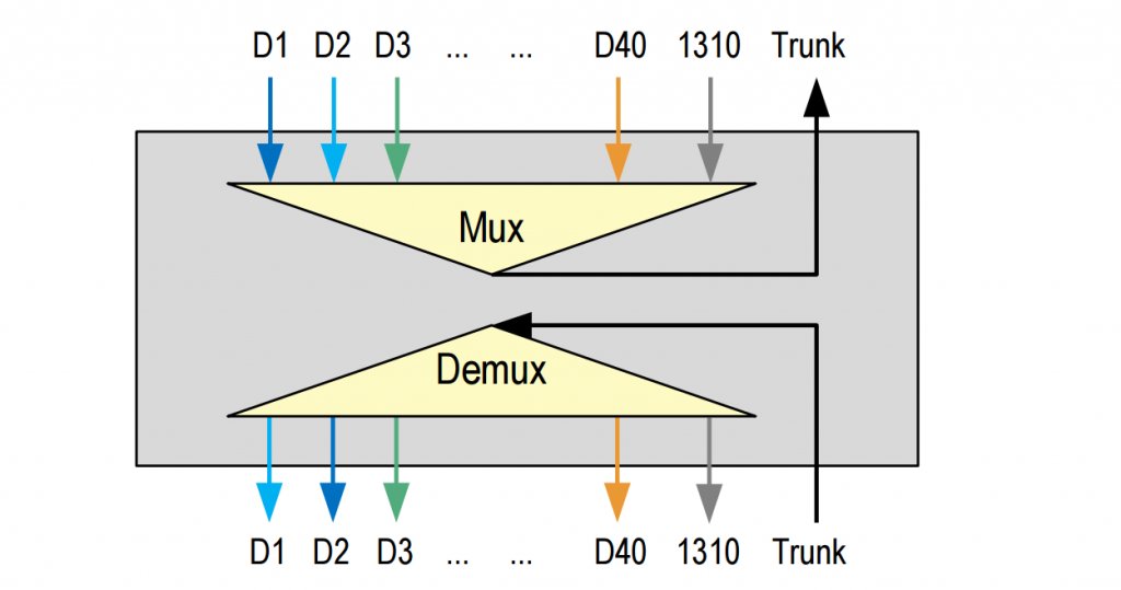
The 1310nm port can be used for 40G/100G transceivers, like 40GBASE-LR4/ER4 or 100GBASE-LR4/ER4 transceivers. The 40G/100G signals can be multiplexed with the other 40*10G signals on the other 40 channels. Together with this pair of 1310 nm port, a 40 CH DWDM MUX/DEMUX can run up to 500G.

The beauty of this port is not limited to data rate increasing. It can also save a lot of money and spaces. You do not need to add another 10 ports and 10 pairs of SFP+ modules for additional 100G transmission. No change in the cabling infrastructure is required. Just a pair of 100G optics and a pair of patch cables, you can get another 100G service. The following picture shows the application of this 40 CH MUX/DEMUX with 1310nm port. (Click the picture to enlarge it.)

40CH DWDM solution

Cabling Solution for 40 CH DWDM MUX/DEMUX With 1310nm Port

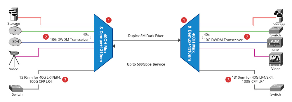
Here offers the detailed cabling solution for this 40CH DWDM MUX/DEMUX with 1310nm port. Kindly contact sales@fs.com for more details.

Item Number ID# FS Part Number Item Description
1 35887 40MDD-1RU-A1-FSDWDM 40 Ch 1RU Duplex DWDM MUX DEMUX C21 to C60 with 1310nm Port and Monitor Port
2 14491 DWDM-SFP10G-40 10GBASE 100GHz DWDM SFP+ 40km, LC Duplex Interface, C21 to C60
31533 DWDM-SFP10G-80 10GBASE 100GHz DWDM SFP+ 80km, LC Duplex Interface, C21 to C60
14599 DWDM-XFP10G-40 10GBASE 100GHz DWDM XFP 40km, LC Duplex Interface, C21 to C60
14650 DWDM-XFP10G-80 10GBASE 100GHz DWDM XFP 80km, LC Duplex Interface, C21 to C60
3 35208 QSFP-LR4-40G 40G QSFP+ LR4 1310nm 10km, LC Duplex Interface
35210 QSFP-ER4-40G 40G QSFP+ ER4 1310nm 40km, LC Duplex Interface
35014 CFP2-LR4-100G 100G CFP2 LR4 1310nm 10km, LC Duplex Interface

Basics of Optical Isolator

In a fiber optic system, connectors and optical devices on the output of the transmitter may cause reflection, absorption, or scattering of the optical signal. These effects may cause light energy to be reflected back at the source and interfere with source operation. In order to reduce the effects of interference, you may need an optical isolator. An optical isolator, or optical diode, is an optical component which allows the transmission of light in only one direction. It is typically used to prevent unwanted feedback into an optical oscillator, such as a laser cavity. The operation of the device depends on the Faraday effect (which in turn is produced by magneto-optic effect), which is used in the main component, the Faraday rotator.

Working Principle of Optical Isolator

An optical isolator contains three components, an input polarizer, a Faraday rotator and an output polarizer. As showed in Figure 1, light traveling in the forward direction passes through the input polarizer and becomes polarized in the vertical plane. Upon passing through the Faraday rotator, the plane of polarization will have been rotated 45° on axis. The output polarizer, which has been aligned 45° relative to the input polarizer will allow the light to pass unimpeded. As Figure 2 illustrates, light traveling in the reverse direction will pass through the output polarizer and become polarized at 45°. The light will then pass through the Faraday rotator and experience an additional 45° of nonreciprocal rotation. The light is now polarized in the horizontal plane and will be rejected by the input polarizer which only allows light polarized in the vertical plane to pass unimpeded.

optical isolator working principle

Types of Optical Isolator

According to the polarization characteristics, optical isolator can be divided into polarization independent type and polarization dependent type.

The polarization dependent isolator, or Faraday isolator, is made of three parts, an input polarizer, a Faraday rotator, and an output polarizer, called an analyser (polarized at 45°). Polarization dependent isolators are typically used in free space optical systems. This is because the polarization of the source is typically maintained by the system. In optical fiber systems, the polarization direction is typically dispersed in non polarization maintaining systems. Hence the angle of polarization will lead to a loss.

The polarization independent isolator is made of three parts, an input birefringent wedge, a Faraday rotator, and an output birefringent wedge. Typically collimators are used on either side of the isolator. In the transmitted direction, the beam is split and then combined and focused into the output collimator. In the isolated direction the beam is split, and then diverged, so it does not focus on the collimator.

Applications

Optical isolator is used in many optical applications in corporate, industrial, and laboratory settings. They are reliable devices when used in conjunction with fiber optic amplifiers, fiber optic ring lasers, fiber optic links in CATV applications, and high-speed and coherent fiber optic communication systems. Single polarization fiber optic isolators are also used with laser diodes, gyroscopic systems, optical modular interfaces, and a variety of other mechanical control and testing applications.

Conclusion

From the text, we can get basic Knowledge of optical isolator. It plays an important role in fiber optic system by stopping back-reflection and scattered light from reaching sensitive components, particularly lasers. For more information about optical isolator, you can visit Fiberstore.

Related articles: Understanding Fiber Optic Cable Jacket & Fire Rating

                             Fiber Connectors Types: SC APC vs SC UPC

GPON: Optimal Solution to FTTH

Recently, the increasing spread of the Internet is the major driver for the development of new access technologies, which demand more capacities carry to bandwidth. Among these technologies, Fiber to the Home (FTTH) becomes the most suitable choice. An optimal option for FTTH technology, Gigabit Passive Optical Network (GPON) provides one of the most cost-effective ways to bandwidth-intensive applications and establishes a long-term strategic position in the broadband market.

GPON Applies in FTTH

Gigabit Passive Optical Network provides the reliability and performance expected for business services and an attractive way to deliver residential services. It enables Fiber to the Home (FTTH) deployments economically resulting to accelerate growth worldwide. The following picture shows how the GPON OLT device deployed in a typical GPON network delivers services to residential homes. Signals from the central office OLT transmits to the splitter, then the splitter spreads the signal to the GPON ONT which connects residential homes.

GPON-FTTH

Features of the GPON Networks
  • Provide downstream speeds of 2.5 Gbps and upstream speeds of 1.25 Gbps.
  • Support long distances of up to 20 km and unlike copper does not suffer from decreasing performance over distance.
  • Standards based and equipment are available from a large and growing number of vendors giving service providers the peace of mind with being locked into a single vendor.
  • Inherently secure wherein wiretapping, eavesdropping and other hacking is nearly impossible.
Advantages of GPON Networks

The most obvious advantage of PON networks is that a single shared optical fiber can support multiple users through the use of inexpensive passive optical splitters. In GPON networks, up to 64 ONTs can share one fiber connection to the OLT. This makes Gigabit Passive Optical Network an attractive option for service providers wanting to replace copper networks with fiber, particularly in high-density urban areas.

  • Allow service providers to deliver more capacity to carry bandwidth-intensive applications.
  • Provide one of the most cost-effective ways for a service providers to deploy fiber.
  • Provide a future proof mode of access as the speed of the broadband connection is limited by the terminal equipment rather than the fiber itself. Future speed improvements can be achieved via equipment upgrades before any upgrades on the fiber itself.
Conclusion

Demands for access networks have promoted deployment of FTTH technologies. As an optimal solution to these technologies, GPON provides the unique features and advantages applied in FTTH. To meet the demand of Gigabit Passive Optical Network in access networks worldwide, Fiberstore has developed GPON/EPON system solutions. For more information about it, please visit Fiberstore.

Passive Optical Components: Optical Circulator

In order to meet the growing demand of communication efficiency, we always apply optical circulator in a fiber optic system because the optical circulator minimizes the loss of light. An optical circulator is a device used in optical communications systems, which can be used to separate optical signals that travel in opposite directions in an optical fiber, analogous to the operation of an electronic circulator.

Components and Working Principle

Optical circulator is commonly made of as following optical components: polarizing beam splitter, reflector prism, briefringent blocks, Faraday rotator, and retardation plate.

The operation way of optical circulator is similar to optical isolator. A light travelling in one direction through a Faraday rotator has its polarisation rotated in one particular direction. Light entering the Faraday rotator from the opposite direction has its phase rotated in the opposite direction (relative to the direction of propagation of the light). Another way of looking at this is to say that light is always rotated in the same direction in relation to the rotator regardless of its direction of travel. In a three-port circulator a signal is transmitted from port 1 to port 2, another signal is transmitted from port 2 to port 3, and a third signal can be transmitted from port 3 to port 1. This operation is represented by the following picture.

circulator working principle

Types

By the number of ports, optical circulators usually falls into three types: 3-port, 4-port and 6-port. In general, 3-port and 4-port circulators are quite common, while the 6-port circulators are less commonly used. No matter which port-type of the optical circulators, optical light is transmitted from any of the port in such circulators can be redirected to any other port.

In terms of operation principles, optical circulators can be divided into three types, traditional, waveguide, and holographic. The traditional optical circulators mainly apply spatial walk-off polarizers (SWPs), Faraday rotators (FRs), and half-wave plates (Hs) to implement its function. The waveguide optical circulators utilize a waveguide Mach–Zehnder interferometer to implement the function of SWPs. The holographic optical circulators apply holographic optical elements to replace traditional SWPs.

According to the polarization characteristics, optical circulators can be divided into two types: Polarization Maintaining (PM) and Polarization Insensitive (PI). PM optical circulator is manufactured with polarization maintaining fiber, making them ideal for polarization maintaining applications such as 40Gbps systems or Raman pump applications. PI optical circulator is a compact and high-performance light wave component. This component is equipped with high isolation, low insertion loss, low polarization-dependent loss (PDL) and high stability and reliability. It is widely used in combination with fiber gratings and other reflective components in dense wavelength-division multiplexing (DWDM) systems, high-speed systems and bi-direction communication systems.

Applications

Optical circulator is applied in a wide variety of applications within fiber communication system. In advanced optical communication systems, optical circulator is used for bi-directional transmissions, wavelength division multiplexing networks, fiber amplifier systems, optical time domain reflectrometers, etc.

Conclusion

With key features of high isolation, low insertion loss, low cross talk and large bandwidth, optical circulator can be built into the same device as transmitters, receivers, and amplifiers. For more information about optical circulator, please visit Fiberstore.

Comparison Between CWDM and DWDM

With the rapid development of telecommunications, the demand for cable capacity is stronger more than ever. WDM (Wavelength Division Multiplexing) will be the preferred method to meet the needs. WDM systems are divided into different wavelength patterns, conventional/coarse (CWDM) and dense (DWDM). This post aims to make a comparison between CWDM and DWDM.

WDM and It’s Working Principle

Wavelength Division Multiplexing is a technology which multiplexes a number of optical carrier signals onto a single optical fiber by using different wavelengths of laser light. This technique enables bidirectional communications over one strand of fiber, as well as multiplication of capacity. A WDM system uses a multiplexer at the transmitter to join the signals together, and a demultiplexer at the receiver to split them apart. With the right type of fiber it is possible to have a device that does both simultaneously, and can function as an optical add-drop multiplexer.

CWDM is the technology of choice for cost efficiently transporting large amounts of data traffic in telecoms or enterprise networks.

DWDM is an optical technology used to increase bandwidth over existing fiber optic backbones.

Comparison between CWDM and DWDM will be illustrated from the following aspects:

  • Channel Numbers: DWDM can fit 40-plus channels into the same frequency range which is twice of CWDM can fit. CWDM is used more often than DWDM due to the cost factor. Now that cabling and transmission has become more affordable, DWDM takes place of CWDM. CWDM is defined by wavelengths, while DWDM is defined in terms of frequencies.
  • Modulated laser: Unlike DWDM deploys cooled distributed-feedback (DFB), CWDM is based on uncooled distributed-feedback (DFB) lasers and wide-band optical filters. These technologies provide several advantages to CWDM systems such as lower power dissipation, smaller size, and less cost. The commercial availability of CWDM systems offering these benefits makes the technology a viable alternative to DWDM systems for many metro and access applications.
  • Transmission Distance: Another major difference between the two is that DWDM is designed for longer haul transmission, by keeping the wavelengths tightly packed. It can transmit more data over a significantly larger run of cable with less interference than a comparable CWDM system. If there is a need to transmit the data over a very long range, the DWDM will likely be the priority in terms of functionality of the data transmittal as well as the lessened interference over the longer distances that the wavelengths must travel. CWDM cannot travel long distances because the wavelengths are not amplified, and therefore CWDM is limited in its functionality over longer distances. Typically, CWDM can travel anywhere up to about 100 miles (160 km), while an amplified dense wavelength system can go much further as the signal strength is boosted periodically throughout the run. As a result of the additional cost required to provide signal amplification, the CWDM solution is best for short runs that do not have mission critical data.

From the comparison above, we can know both the benefits and drawbacks of CWDM and DWDM.  If the transmission distance is short and cost is low, then CWDM may be your first choice. On the contrary, you can consider DWDM. For more information about CWDM and DWMD, you can visit Fiberstore.