Tag Archives: optical splitter

GPON: Optimal Solution to FTTH

Recently, the increasing spread of the Internet is the major driver for the development of new access technologies, which demand more capacities carry to bandwidth. Among these technologies, Fiber to the Home (FTTH) becomes the most suitable choice. An optimal option for FTTH technology, Gigabit Passive Optical Network (GPON) provides one of the most cost-effective ways to bandwidth-intensive applications and establishes a long-term strategic position in the broadband market.

GPON Applies in FTTH

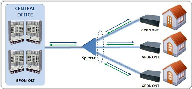
Gigabit Passive Optical Network provides the reliability and performance expected for business services and an attractive way to deliver residential services. It enables Fiber to the Home (FTTH) deployments economically resulting to accelerate growth worldwide. The following picture shows how the GPON OLT device deployed in a typical GPON network delivers services to residential homes. Signals from the central office OLT transmits to the splitter, then the splitter spreads the signal to the GPON ONT which connects residential homes.

GPON-FTTH

Features of the GPON Networks
  • Provide downstream speeds of 2.5 Gbps and upstream speeds of 1.25 Gbps.
  • Support long distances of up to 20 km and unlike copper does not suffer from decreasing performance over distance.
  • Standards based and equipment are available from a large and growing number of vendors giving service providers the peace of mind with being locked into a single vendor.
  • Inherently secure wherein wiretapping, eavesdropping and other hacking is nearly impossible.
Advantages of GPON Networks

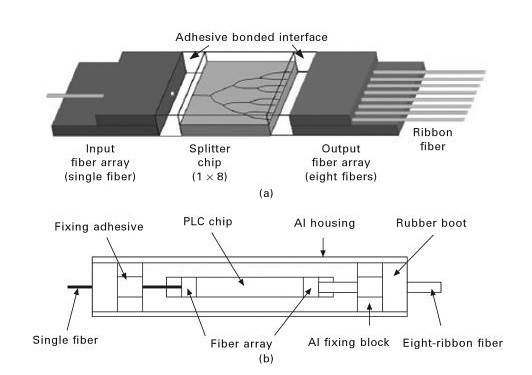
The most obvious advantage of PON networks is that a single shared optical fiber can support multiple users through the use of inexpensive passive optical splitters. In GPON networks, up to 64 ONTs can share one fiber connection to the OLT. This makes Gigabit Passive Optical Network an attractive option for service providers wanting to replace copper networks with fiber, particularly in high-density urban areas.

  • Allow service providers to deliver more capacity to carry bandwidth-intensive applications.
  • Provide one of the most cost-effective ways for a service providers to deploy fiber.
  • Provide a future proof mode of access as the speed of the broadband connection is limited by the terminal equipment rather than the fiber itself. Future speed improvements can be achieved via equipment upgrades before any upgrades on the fiber itself.
Conclusion

Demands for access networks have promoted deployment of FTTH technologies. As an optimal solution to these technologies, GPON provides the unique features and advantages applied in FTTH. To meet the demand of Gigabit Passive Optical Network in access networks worldwide, Fiberstore has developed GPON/EPON system solutions. For more information about it, please visit Fiberstore.

Typical example of photonic packaging

The passive optical power splitter is one of the key elements in a passive optical network (PON), which equally splits the signal power from the optical line terminal (OLT) in the central office (CO) to each optical network unit (ONU). It can branche and couple waves without converting optical transmissions into electric signals, for connecting households to thlecommunication carriers in optical communication networks. Planar lightwave circuits (PLC Splitter) can provide various key practical devices for such optical networks because of their suitability for large-scale integration, long-term stability, and mass production capability. In order to utilize the integration capability of PLC devices, the input and output fibers have to be connected to the PLCs. The fiber connected splitters are required to exhibit not only htgh optical performance (such as low loss, wavelength flatness and low polarization dependence) but also long-term reliability. However, to attain a reliable low loss splitter, connection methods must be precise and meticulous.

Figures1 a and b show typical schematic configurations of an unpackaged and a packaged PLC-type optical splitter, respectively. The unpackaged 1×8 PLC Optical Splitter includes a PLC (splitter) chip, and single-channel (input) and eight-channels (output) fiber arrays. The three parts are mounted by an adhesive, as shown in Fig 1a. However, in a packaged device, the mounted optical splitter is secured in its housing by applying fixing adhesive between the Al fixing blocks and the fibers. Moreover, an adhesive is used to bond the rubber boots and the end of fiber arrays in the housing, as shown in Fig1b. It is very clear that different types of adhesive are nedded for bonding different parts of the PLC package. In fact, a large number of different materials are ultimately required for assembling the splitter packages. Table 1 shows the physical properties of materials used in an adhesive-based optical splitter package. Shows the appearance of a bonded PLC optical splitter package in an aluminum package.

777777777


Figures 1    (a)Schematic configuration of unpackaged PLC optical splitter.

                          (b) Schematic configuration of packaged PLC optical splitter.


Table 1

Physical properties of materials used in adhesive-based packaging of an Optical Splitter

88888888888

Continue reading

Common Passive Fiber Optical Splitters

Fiber optical splitter, also named fiber optic coupler or beam splitter, is a device that can distribute the optical signal (or power) from one fiber among two or more fibers. Fiber optic splitter is different from WDM(Wavelength Division Multiplexing) technology. WDM can divide the different wavelength fiber optic light into different channels, but fiber optic splitter divide the light power and send it to different channels.

Work Theory Of Optical Splitters

The Optical Splitters “split” the input optical signal received by it between two optical outputs, simultaneously, in a pre-specified ratio 90:10 or 80:20. The most common type of fiber-optic splitter splits the output evenly, with half the signal going to one leg of the output and half going to the other. It is possible to get splitters that use a different split ratio, putting a larger amount of the signal to one side of the splitter than the other. Splitters are identified with a number that represents the signal division, such as 50/50 if the split is even, or 80/20 if 80% of the signal goes to one side and only 20% to the other.

Some types of the fiber-optic splitter are actually able to work in either direction. This means that if the device is installed in one way, it acts as a splitter and divides the incoming signal into two parts, sending out two separate outputs. If it is installed in reverse, it acts as a coupler, taking two incoming signals and combing them into a single output. Not every fiber-optic splitter can be used this way, but those that can are labeled as reversible or as coupler/splitters.

Attenuation Of Fiber Optic Splitter

An interesting fact is that attenuation of light through an optical splitter is symmetrical. It is identical in both directions. Whether a splitter is combining light in the upstream direction or dividing light in the downstream direction, it still introduces the same attenuation to an optical input signal (a little more than 3 dB for each 1:2 split). Fiber optic splitters attenuate the signal much more than a fiber optic connector or splice because the input signal is divided among the output ports. For example, with a 1 X 2 fiber optic coupler, each output is less than one-half the power of the input signal (over a 3 dB loss).

Passive And Active Splitters

Fiber optic splitters can be divided into active and passive devices. The difference between active and passive couplers is that a passive coupler redistributes the optical signal without optical-to-electrical conversion. Active couplers are electronic devices that split or combine the signal electrically and use fiber optic detectors and sources for input and output.

Passive splitters play an important position in Fiber to the Home (FTTH) networks by permitting a single PON (Passive Optical Network) network interface to be shared amongst many subscribers. Splitters include no electronics and use no power. They’re the community parts that put the passive in Passive Optical Network and are available in a wide range of break up ratios, including 1:8, 1:16, and 1:32.

Optical splitters are available in configurations from 1×2 to 1×64, such as 1:8, 1:16, and 1:32. There are two basic technologies for building passive optical network splitters: Fused Biconical Taper (FBT) and Planar Lightwave Circuit (PLC). FBT Coupler is the older technology and generally introduces more loss than the newer PLC Splitter.