As was mentioned earlier, an FBG resonance wavelength shifts with the mechanical strain it is subject to. So, if the FBG is cemented to a structure, it is possible to calculate its strain by measuring the FBG resonance wavelength, the wavelength at which it reflects the light impinging on it along its connecting optical fibre.
Basically, the way to measure the strain is to launch into the fibre optical pulses at different wavelengths, and to measure the reflections coming back from the FBG. Since only the pulses whose wavelength matches the FBG resonance are reflected, by keeping track of the reflected pulses the resonce wavelength is determined, and from it the strain.
In the measurement system shown in Fiber Splitter, the wavelength encoded optical pulses are generated at the tunable laser, propagate along the feeder fibre and break into up to 32 equal replicas at the splitter. Since all arrays are nominally equal, it is very probable that several FBGs reflect at the same wavelength. When that happens, for each pulse there are several reflections which combine at the splitter and arrive together at the detector, whose associated control circuitry has somehow to resolve them, and to determine what is reflecting from where.
To understand how this is achieved, it is now necessary to leave the simple system description from Fiber Splitter and turn to a more comprehensive one, which is shown in Figure 1.
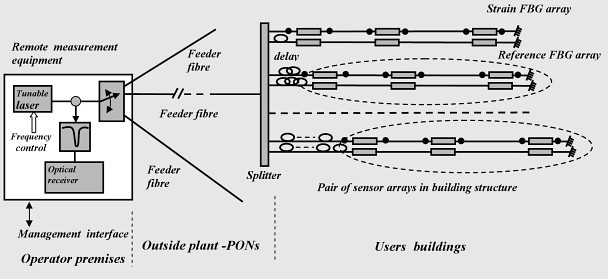
Figure 1
As can be deduced from Figure 1, even though all arrays are nominally equal, their distance to the Fiber Splitter is different. From each array to the Fiber Splitter there is a fibre section, and the lengths of these sections are all different. In Figure 1 the sections are marked with the term “delay”, since their purpose is to force a differential delay between all reflections impinging back on the Fiber Splitter at a same wavelength.
So, the way to identify at the optical receiver which reflections is coming from which FBG is to make use of the fact that FBGs resonating at the same wavelength are placed at different distances to the measurement equipment; in short, what has to be done is to resolve distances. The standard method to resolve distance, the so called Optical Time Domain Reflectometry, OTDR, consists on sending along the fibre short optical pulses, and measuring the time it takes for their reflections to reach the measurement equipment receiver. In this way, both the position and intensity of the reflections along the optical fibres can be determined. And, as has been stressed, it is also required that each pulse has a differrent wavelegth.
At this moment an additional drawback turns up. For the tunable laser used in this project, in fact for all tunable lasers applicable to this measurement principle of operation, the procedure of turning on and off the laser output to generate pulses at differnt and precisely determined wavelengths is, regretably, unfeasible, because when the laser is turned on it takes a few seconds for its wavelength to stabilize, whereas the pulse duration shouled be no longer than a few hundred nanoseconds. (Related products in: Fiber Amplifier)
One alternative procedure equivalent to turning the laser on and off, which is f easible with the kind of state of the art tunable lasers recommended by this project, is to take advantage of the lasers fast wavelength switching speed (tens os ns). It is shown schematically in Figure 1. Its principle of peration is to divide the optical wavelength space in two bands: the first one, or “on band”, contains the Bragg gratings resonance frequencies, and the second one, “off band”, is empty of them. The laser addresses the gratings not with optical intensity pulses, but with p ulses in the wavelength domain, i.e. short petiods of time with output in the “on band”, followed by longer periods, which will be termed “off periods”, during which the frequency is in the “off band”. The receiver is preceded by a band reject, or notch, filter which eliminates the “off band”. Thus, it is reached by reflected optical pulses which are identical to those which would be receivede if the laser could be really turned off during its “OFF period”. The notch filter is readily implemented with a Bragg grating, whose key parameters to be specified are its reject band and insertion losses. This measurement procedure, or interrogation strategy, will be termed Frequency Shift Keying (FSK) OTDR, since the frequency, or wavelength, both terms are equivalent, is modulated, keyed, in discrete steps.