DWDM network has been widely accepted as the most cost-effective and feasible solution to increase the fiber optic network capacity over long distance. Except the bandwidth, the transmission distance is also an important factor during the deployment of DWDM network. This post is to introduce how to ensure and extend the transmission distance in DWDM network.
Generally, the fiber optic transmission distance is affected by the data rate, light loss, light source, etc. During the deployment, technicians usually need to select proper fiber optic transceivers to ensure the light source is strong enough to support the long transmission distances. For instance, 1G DWDM SFP modules provided by the market can usually support transmission distance up to 100km, while for 10G DWDM SFP+ modules this distance decrease to 80km. If the longer transmission distance is to achieve, proper fiber optic devices should be added in the DWDM network to ensure the transmission quality. The following part will take the examples of 10G DWDM network which uses DWDM SFP+ modules supporting transmission distance up to 80km on both ends of the fiber link. This 10G DWDM network will be required to support fiber optic links up to 40km, 80km, 120km and 200km separately.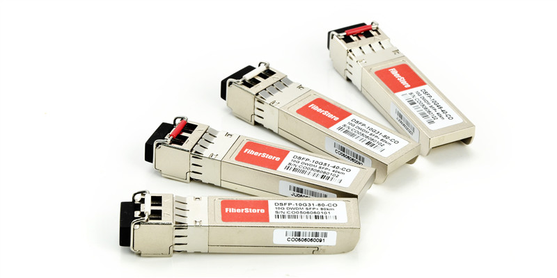
In this first case, this 10G DWDM network is required to support 40km transmission distance. As we are using the 80km DWDM SFP+ modules, if there are no other locations deployed between the two ends of this network, generally no other devices are required to be installed between the two DWDM MUX/DEMUXs. The light source of 80km DWDM SFP+ modules can support 10G transmission over 40km.
If this DWDM network is required to support 80km transmission distance, we will still use the 80km DWDM SFP+ modules. The light source of these 80km DWDM SFP+ modules might not be able to support such long transmission distance, as their might have light loss during transmission. In this case, pre-amplifier (PA) is usually deployed before the receiver to improve the receiver sensitivity and extend signal transmission distance. Meanwhile, the dispersion compensation module (DCM) can be added in this link to handle the accumulated chromatic dispersion without dropping and regenerating the wavelengths on the link. The following diagram shows the deploying method of this 80km DWDM network.
It is known that the light power will decrease with the increasing of transmission distance. More fiber optic devices should be added in the 120km DWDM network to amplify the optical signal transmission from the 80km DWDM SFP+ modules. The following diagram shows how to deploy this 120km DWDM network. Except the above mentioned pre-amplifier and dispersion compensation module, a booster EDFA (BA) is suggested to deploy before at the beginning of the transmitting side to further ensure optical signal can achieve 120km.
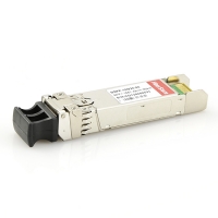
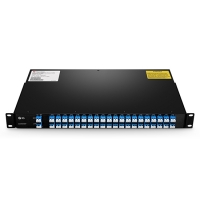
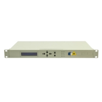
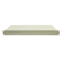
The above cases just simply illustrate the deployment of 40km, 80km and 120km 10G DWDM network that uses 80km DWDM SFP+ modules as light source. Related products in the above mentioned cases are listed in the following table. Please note that during the deployment of these long haul DWDM network, the light loss and compensation dispersion should be well calculated.
 |
 |
 |
 |
| DWDM SFP+ 80km | DWDM MUX/DEMUX | Optical Amplifier | Dispersion Compensation Module |
In fact, DWDM technologies and products can achieve transmission distance much longer than 120km, like 170km DWDM and 200km DWDM. If you are interested, kindly visit our Long Haul DWDM Network page where you can find specific details for complete DWDM network deployment solutions.
