Author Archives: Alice Gui

PoE in Enterprise Network

In traditional data communication network, a network connection and a power connection are required. However, with PoE technology, only the ordinary Ethernet network cable is required. PoE (Power over Ethernet) is a technology designed to allow the existing Ethernet network cable to deliver direct electrical current flows. It has a lot of advantages like lower cost, easier maintenance, less down time and great flexibility during management and network installation. A variety of products have been designed to make full use of PoE technology. This post will introduce these PoE based products and how to use them in our network.

PoE switch

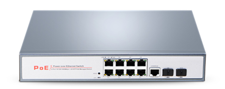
PoE switch is the most important device is you are going to use PoE technology. It is the PoE switch that transmission the necessary data and power flow together to other PoE devices. Not all the devices can be powered by PoE switches, as the electrical power provided by a PoE switches is limited. For instance, the IEEE 802.3af guarantees only 12.95 W of power on a given connection. Thus, if your devices required power higher than that, then the PoE cannot work out under this standard. The power that a PoE can provide for connections differs according to the technologies. And the port type and port numbers that PoE switches provided are various. Generally, PoE switches provided in the market can provide SFP ports for uplink and RJ45 ports for downlink. Here offers several different PoE

PoE Switch Port Detail Power Supply for PoE Port Max. Power Consumption
PS130W-8 8 PoE ports, 2 SFP ports 15.4W 130W
PS250W-8 8 PoE ports, 2 SFP ports 30W 250W
PS400W-24 24 PoE ports, 4 SFP ports 15.4W 400W
PS650W-24 24 PoE ports, 4 SFP ports 30W 650W
PS650W-48 48 PoE ports, 4 SFP+ ports 30W 350W

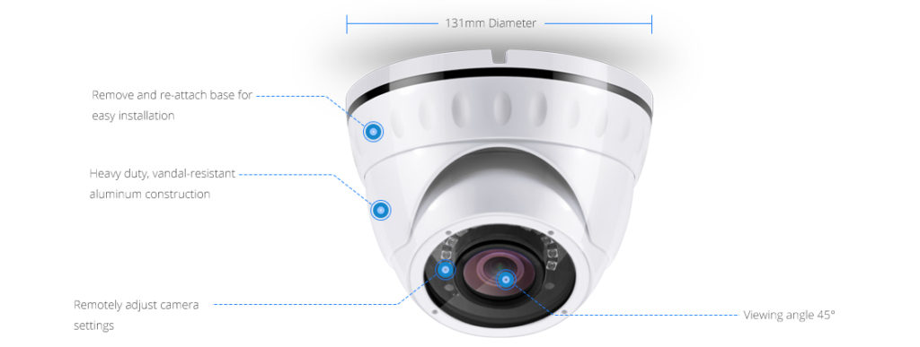
In many public places or even our own houses, camera is installed for surveillance These cameras are usually required to be connected to the Ethernet or monitor. As the power required by camera is not high and the places they deployed are usually lack of power outlet, IP camera which supports PoE is very popular. With a RJ45 port, the PoE IP Camera can be connected to the switch for data communication. The following picture shows a Camera that support both Ethernet network cable and additional power cords.

PoE IP Camera

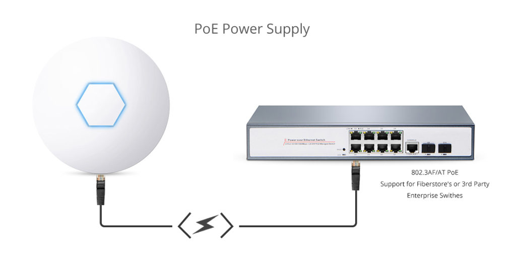
WiFi is necessary in most places now. In the public places like hospital, hotel, or office, wireless access points are usually installed to transfer the data from Ethernet network cable into WiFi signals. Wireless access point is usually installed on the ceiling, where power outlet seldom installed. Thus, PoE wireless access pointer is a preferred choice in most public places. As wireless access point just needs low voltage power support, the network cable is able to provide enough power that it required.

PoE wireless access point

Network Making Full Use of PoE technology

Telecommunication network using PoE technology has a wide range of applications. It is usually installed at enterprise network like office building. The following picture shows a sample of small network using PoE technology.

PoE network

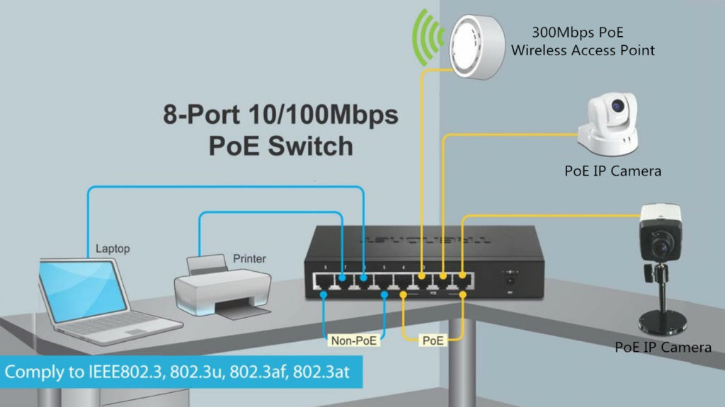
An 8-port PoE switch is being used to connect devices in a small office. The eight ports of PoE switch are set into support four Non-PoE ports and four PoE port. The devices like laptop and printer required high voltage power supply is connected to the non-PoE ports for data communication. Devices like 300 Mbps wireless access point with PoE function, and two PoE IP cameras that requires low voltage power supply, are connected to PoE port of this switch for both power supply and data communication.

The using of PoE switch, camera, and wireless access point is flexible and convenience. To provide higher speed data transmission and more applications is the trend of PoE devices developing. Meanwhile, the power that these PoE switch can supply is also increasing gradually.

Related Article: Introduction to PoE Networking Architectures

Cisco S-Class vs Non-S-Class Module

Cisco switches and fiber optic transceivers are considered as the benchmarks of the market with a market share more than 50%. With the development of fiber optic network, Cisco has developed a variety of fiber optic transceivers for different applications and has built a system to name each transceiver. For instance, the most commonly used 10G Cisco modules like SFP-10G-SR and SFP-10G-LR have part numbers which can accurately descript their biggest features. SR means “short range” and LR means “long range”. However, customers find the part numbers of some Cisco modules are named with an “S”, like SFP-10G-SR-S and SFP-10G-LR-S. Cisco calls them S-class modules. People might get confused by these Cisco S-class modules. Cisco S-Class vs Non-S-Class module, or SFP 10G SR S vs SFP 10G SR, which one should you choose?

sfp 10g sr s vs sfp 10g sr

Cisco S-Class Module VS Cisco Non-S-Class Module

Cisco only published four 10G S-class SFP+ modules and two 40G S-class QSFP+ modules. The following table listed Cisco S-class modules. Cisco S-class modules seem to have no differences from the non-S-class modules. However, if you read the specification of these modules and the suggestions from Cisco, you will find the differences.

Data Rate S-Class Module Non-S-Class Module Media
10G SFP-10G-SR-S SFP-10G-SR MMF (duplex)
10G SFP-10G-LR-S SFP-10G-LR SMF (duplex)
10G SFP-10G-ER-S SFP-10G-ER SMF (duplex)
10G SFP-10G-ZR-S SFP-10G-ZR SMF (duplex)
40G QSFP-40G-SR4-S QSFP-40G-SR4 MMF (ribbon)
40G QSFP-40G-LR4-S QSFP-40G-LR4 SMF (duplex)

Protocol

The standard non-S-class Cisco modules like SFP-10G-SR and SFP-10G-LR can support three protocols including Ethernet, OTN (Optical Transport Network) and WAN-PHY (Wide Area Network Physics). However, the S-class modules can only support Ethernet protocol.

Temperature Range

Compared with Cisco C-class modules which can be operating with three different temperature ranges, the Cisco S-class modules can only support the commercial temperature ranges which is 0 to 70°C (32 to 158°F).

  • Commercial temperature range (COM): 0 to 70°C (32 to 158°F)
  • Extended temperature range (EXT): -5 to 85°C (23 to 185°F)
  • Industrial temperature range (IND): -40 to 85°C (-40 to 185°F)

Transmission Distance

Cisco has introduced that the S-class modules are suggested to be used in enterprise network. In addition, the operating temperature range is smaller, thus, S-class module is recommended for shorter transmission distance applications compared with other standard modules.

Price

As the performance of Cisco S-class modules are no better than other modules, why did Cisco published these modules? This is because Cisco S-class modules have lower prices, which is also their biggest sale point.

cisco s-class module

Should I Choose Cisco S-Class Module?

In conclusion, S-class can only support Ethernet protocol and has a commercial temperature range, which is suggested to be used in applications that no special long distance, temperature tolerances, or other special features are required. But many people might not select S-class modules, considering about the future use. As Cisco original branded transceivers are expensive, many people will use third party modules which are much cheaper but is compatible with Cisco devices. A Cisco compatible non-S-class module could be much cheaper than a Cisco original brand S-module. But it can provide almost the same performance as the Cisco original branded non-S-class module.

Related Article: Cisco SFP-10G-SR: All You Need to Know

A Comprehensively Understanding of Cisco 10GBASE SFP+ Modules

Differences Between Pre-Amplifier, Booster Amplifier and In-line Amplifier

Transmission distance has always been a key factor during deployment of fiber optic network. DWDM technologies, which are considered as the most cost-effective ways to increase the network capacity over long transmission distance, have been widely applied in our telecommunication network. To further extend the transmission distance of optical signals transmission from the DWDM fiber optic transceivers, optical amplifiers are usually used in the DWDM network. Different types of optical amplifiers have been invented to meet the signal amplifying requirements in different situations. This post will introduce the differences between the three most commonly used optical amplifiers: pre-amplifier, booster amplifier, and in-line amplifier.

Basics of Optical Amplifier

In the past, if you want to extend the transmission distance of DWDM network, an optical regenerator station is required to be installed in the fiber link every 80km to 100km. The regenerator station will electronically regenerate the optical signals to overcome the power loss and ensure that the optical signal can be detected at the receiver end. However, this requires a lot of money and is not easy to upgrade the whole network.

With optical amplifier, things become much easier. The optical amplifier can enlarge the optical signals without regeneration. In addition, the network upgrading is more cost-effective with optical amplifier. Each optical amplifier has an important factor which is operation gain measured in dB. The operation gain of the optical amplifier should be carefully calculated to ensure network performance. Pre-amplifier, booster amplifier and in-line amplifier are used in different places in the fiber optic network. And they support different operation gains according to the whole network requirement.

Pre-Amplifier, Booster Amplifier and In-line Amplifier

Pre-Amplifier is usually installed at the receiver end of the DWDM network to amplify the optical signal to the required level to ensure that it can be detected by the receiver. The following picture shows a typical diagram for a duplex 10G DWDM network that can support 80km. A pre-amplifier is installed at each receiving end of this network. There will be great power loss after the optical signal goes through the 80km optical fiber. Then, a pre-amplifier installed at the receiver end is necessary. Generally, a pre-amplifier should offer high gain to ensure that the optical signal is detectable.

pre-amplifier

Booster Amplifier is installed in the transmitting end of the fiber optic network, which can amplifier amplify the optical signal launched into the fiber link. It is usually used in DWDM network where the multiplexer attenuates the signal channels. The following picture shows a 10G DWDM network using booster amplifier (BA) at the transmitting end and pre-amplifier (PA) at receiving end. Thus, this 10G DWDM network can support a transmission distance much longer than the above-mentioned one. Please note, a DCM (Dispersion Compensation Module) is added in this network to further ensure the transmission quality. A booster amplifier usually provides low gain and high output power.

booster amplifier

In-line Amplifier is easy to understand. The gain provided by the pre-amplifier and booster amplifier might not be enough due to the optical loss caused by long haul transmission. In-line amplifier is installed in the fiber optic link every 80-100km as shown in the following picture. It has moderate gain and has similar output power to those of booster amplifier.

in-line amplifier

Conclusion

The optical amplifier can help to amplifier the optical power during long haul transmission to ensure that the receiver can detect the optical signal without error. Three amplifiers are commonly used in DWDM network. Booster amplifier is used to amplifier optical power at the transmitting end and pre-amplifier is placed at the receiver end. If the transmission distance is longer than 150km or have great power loss during transmission, in-line amplifier is suggested to be installed every 80km to 100k in the fiber optic link. The gain of these amplifiers should be carefully calculated during practical use. Kindly visit DWDM EDFA Amplifier page for more details.

Related Article: Introduction of Optical Amplifier

Related Article: Optical Amplifier – EDFA (Erbium-doped Fiber Amplifier) for WDM System

How to Extend Transmission Distance in DWDM Network?

DWDM network has been widely accepted as the most cost-effective and feasible solution to increase the fiber optic network capacity over long distance. Except the bandwidth, the transmission distance is also an important factor during the deployment of DWDM network. This post is to introduce how to ensure and extend the transmission distance in DWDM network.DWDM MUX/DEMUX

Proper DWDM Fiber Optic Transceiver Is Essential

Generally, the fiber optic transmission distance is affected by the data rate, light loss, light source, etc. During the deployment, technicians usually need to select proper fiber optic transceivers to ensure the light source is strong enough to support the long transmission distances. For instance, 1G DWDM SFP modules provided by the market can usually support transmission distance up to 100km, while for 10G DWDM SFP+ modules this distance decrease to 80km. If the longer transmission distance is to achieve, proper fiber optic devices should be added in the DWDM network to ensure the transmission quality. The following part will take the examples of 10G DWDM network which uses DWDM SFP+ modules supporting transmission distance up to 80km on both ends of the fiber link. This 10G DWDM network will be required to support fiber optic links up to 40km, 80km, 120km and 200km separately.DWDM SFP+

Case Study One: 40km DWDM Network

In this first case, this 10G DWDM network is required to support 40km transmission distance. As we are using the 80km DWDM SFP+ modules, if there are no other locations deployed between the two ends of this network, generally no other devices are required to be installed between the two DWDM MUX/DEMUXs. The light source of 80km DWDM SFP+ modules can support 10G transmission over 40km.40km DWDM network

Case Study Two: 80km DWDM Network

If this DWDM network is required to support 80km transmission distance, we will still use the 80km DWDM SFP+ modules. The light source of these 80km DWDM SFP+ modules might not be able to support such long transmission distance, as their might have light loss during transmission. In this case, pre-amplifier (PA) is usually deployed before the receiver to improve the receiver sensitivity and extend signal transmission distance. Meanwhile, the dispersion compensation module (DCM) can be added in this link to handle the accumulated chromatic dispersion without dropping and regenerating the wavelengths on the link. The following diagram shows the deploying method of this 80km DWDM network.80km DWDM network

Case Study Three: 120km DWDM Network

It is known that the light power will decrease with the increasing of transmission distance. More fiber optic devices should be added in the 120km DWDM network to amplify the optical signal transmission from the 80km DWDM SFP+ modules. The following diagram shows how to deploy this 120km DWDM network. Except the above mentioned pre-amplifier and dispersion compensation module, a booster EDFA (BA) is suggested to deploy before at the beginning of the transmitting side to further ensure optical signal can achieve 120km.120km DWDM network

The above cases just simply illustrate the deployment of 40km, 80km and 120km 10G DWDM network that uses 80km DWDM SFP+ modules as light source. Related products in the above mentioned cases are listed in the following table. Please note that during the deployment of these long haul DWDM network, the light loss and compensation dispersion should be well calculated.

80km DWDM SFP+ DWDM MUX/DEMUX DWDM optical amplifier  Dispersion Compensation Module
DWDM SFP+ 80km DWDM MUX/DEMUX Optical Amplifier Dispersion Compensation Module
FS.COM Long Haul DWDM Solution

In fact, DWDM technologies and products can achieve transmission distance much longer than 120km, like 170km DWDM and 200km DWDM. If you are interested, kindly visit our Long Haul DWDM Network page where you can find specific details for complete DWDM network deployment solutions.

How to Build A Single-Fiber CWDM Network

In most fiber optic network, dual-way transmission is necessary, which is usually achieved via duplex fiber cable. However, in some cases, simplex fiber cable can also support dual-way transmission like network that uses BiDi modules. For instance, if you used a pair of BiDi fiber optic transceivers with one using 1270nm for TX and 1310nm for RX, the other BiDi module should use the same but reversed wavelengths for TX and RX on the other end of the fiber link. Thus, a pair of dual-way signal can be transmitted on the same fiber via two different wavelengths. When it comes to build a single-fiber CWDM network, things will be a little different. However, the basic principle is similar, which is using different pairs of wavelengths to transmit different pairs of dual-way signal.

Single-Fiber CWDM MUX/DEMUX

To build a CWDM network, CWDM MUX/DEMUX should be deployed on each end of the fiber optic link. There is also single-fiber CWDM MUX/DEMUX which is used to combine different wavelengths over the same fiber for dual-way transmission. Unlike dual-fiber CWDM MUX/DEMUX which uses the same wavelength for a pair of dual-way signal transmission, single-fiber CWDM MUX/DEMUX uses two different wavelengths for each pair of dual-way signal. A 4-channel dual-fiber CWDM MUX/DEMUX only uses four different wavelengths. However, a 4-channel single-fiber CWDM MUX/DEMUX will use eight different wavelengths which are divided into four pairs for dual-way transmission.

9-ch single-fiber CWDM
TX 1270nm 1310nm 1350nm 1390nm 1430nm 1470nm 1510nm 1550nm 1590nm
RX 1290nm 1330nm 1370nm 1410nm 1450nm 1490nm 1530nm 1570nm 1610nm

The above picture shows a 9-channel single-fiber CWDM MUX/DEMUX which uses 9 of the CWDM wavelengths for transmitting and the other 9 CWDM wavelengths for receiving. There are one simplex line port and 9 duplex channel ports loaded on the front panel. And each duplex channel port uses two different wavelengths which are clearly marked on the front panel. The following picture is also a 9-channel single-fiber CWDM MUX/DEMUX which is used together with the above one. However, the ports for TX and RX are all reversed to ensure the dual-way transmission.

9-ch single-fiber CWDM
RX 1290nm 1330nm 1370nm 1410nm 1450nm 1490nm 1530nm 1570nm 1610nm
TX 1270nm 1310nm 1350nm 1390nm 1430nm 1470nm 1510nm 1550nm 1590nm
CWDM Transceiver Selection for Single-Fiber CWDM MUX/DEMUX

To build a single-fiber CWDM network, CWDM fiber optic transceiver installed on devices like switches is usually connected to the channel port of CWDM MUX/DEMUX. However, as the channel port on the single-fiber CWDM MUX/DEMUX support two different wavelengths. The selection of CWDM fiber optic transceivers for this type of MUX/DEMUX might be confusing. Actually, it is quite simple. You just need to consider about the wavelength TX (transmitting) port. For instance, if one of the duplex port uses 1270nm for TX and the other use 1290nm for RX, then the a 1270nm CWDM transceiver should be used for this ports. While on the other end of this link, a 1290nm CWDM transceiver is required.

The following picture shows a 10G 4-channel single-fiber CWDM network which can better illustrate how to use single-fiber CWDM MUX/DEMUXs and how to select CWDM fiber optic transceivers for single-fiber CWDM MUX/DEMUX. Each wavelength just runs on one direction in single-fiber CWDM network.single-fiber CWDM network

Conclusion

Connecting the CWDM fiber optic transceivers installed on switches with the correspond channel ports on the single-fiber CWDM MUX/DEMUX and connect the line ports of the two CWDM MUX/DEMUXs via single-mode simplex fiber, a simple single-fiber CWDM network can be built. The above content just offers the basic concept of how a single-fiber CWDM network is like. There are actually a lot of factors to be considered during practical deployment, like light loss, transmission distance, and optical signal dropping and adding. IF you are interested, kindly visit FS.COM for more details.