Author Archives: Alice Gui

Which Fiber Optic Wall Plate Do You Use?

With the expansion of fiber optic network, fiber optic cables are widely deployed in buildings and houses to be closer to end users. In many cases, fiber optic cables are installed in-wall. And fiber optic wall plates are used to provide easier and safer connection between the feed cables and the fiber patch cables that are linked to the target devices. Customers should select the right types of fiber optic wall plate to ensure the performance and connection of the fiber links.

Size and Design of Fiber Optic Wall Plate

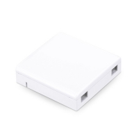
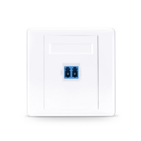
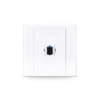
Fiber optic wall plates have different sizes. But the most commonly used fiber optic wall plates are with a size of 86mm*86mm. The design (orientation) of the fiber optic wall plate also varies according to different applications. There are mainly three designs: straight, box and angled which are shown in the following pictures.

straight fiber wall plate
box fiber wall plate
angled fiber wall plate

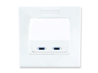
The straight fiber optic wall plates are most commonly used one in many offices and buildings. They can provide architectural design for in-wall and recessed installations. The box type fiber optic wall plates are usually used in FTTH applications to provide easy connecting environments and safe places for fiber patch cable storage. The angled fiber optic wall plate has better performance to decrease the bend loss cause the fiber patch cable would have a smaller bend radius after connected to these wall plates (as shown in the following picture).

Fiber Adapter Type of Fiber Optic Wall Plate

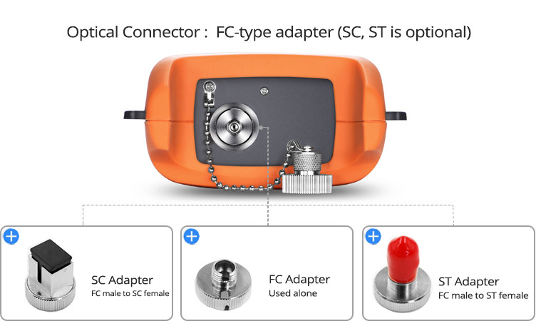
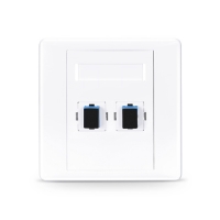
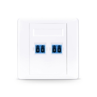
Fiber optic wall plate uses the fiber adapter installed on itself to provide the connection and disconnection for fiber optic cables. Thus, the selection of fiber adapter type on the wall plate is essential. There are fiber optic wall plates which installed with SC, LC, FC, ST, etc. Both simplex and duplex adapters are also available in the market. The fiber type and polishing type of the fiber optic adapters should also be considered if you want to choose the right one for your application.

Port Counts of Fiber Optic Wall Plate

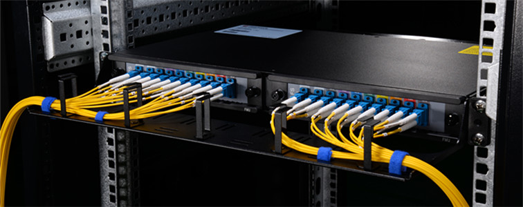
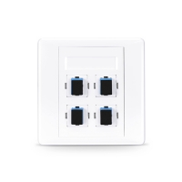
Except the above mentioned factors, the port count that a fiber optic wall plate can provide should also be considered. The port count of fiber optic wall plate with a size of 86mm*86mm is usually ranging from one to four. For most FTTH box type fiber optic wall plate there are usually two ports, one for feed fiber cable, and one for fiber patch cable that is connected to the target device, which is shown in the following picture.

Same-Day Shipping Fiber Optic Wall Plates

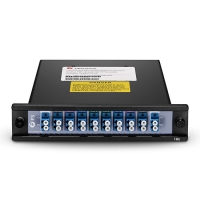
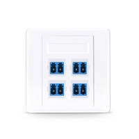
After considering the size, design, fiber adapter type and port count of the fiber optic wall plate, you will roughly know which fiber optic connector is suitable for your applications. The following picture shows part of the commonly used fiber optic wall plates which are available for same-day shipping.

SC Simplex Fiber Optic Wall Plate 2-port SC Fiber Optic Wall Plate 4-port SC Fiber Optic Wall Plate
Single Port SC Simplex Fiber Optic Wall Plate 2-Port SC Simplex  Fiber Optic Wall Plate 4-Port SC Simplex Fiber Optic Wall Plate
LC duplex fiber optic wall plate 2-port LC duplex Fiber Optic Wall Plate 4-port-lc-wall-plate
Single Port LC Duplex Fiber Optic Wall Plate 2-Port LC Duplex  Fiber Optic Wall Plate 4-Port LC Duplex Fiber Optic Wall Plate

Kindly contact sales@fs.com for more details about fiber optic wall plate, if you are interested.

Source: Fiber Optic Wall Plate Selection Guide

How to Build DWDM Network Over CWDM Network

Using CWDM MUX/DEMUX has been widely accepted as the most cost-effective and time-save method to increase the existing fiber optic network without adding optical fibers. However, a CWDM network can only support up to 18 different wavelengths. Is there any possibility to increase the capacity of the existing CWDM network? Hybrid CWDM and DWDM network is being introduced to combine the DWDM wavelengths with the existing CWDM wavelengths.

Combing DWDM With CWDM to Increase Network Capacity

As we know the CWDM wavelengths ranging from 1260nm-1625nm with space channel of 20nm actually cover all the range of DWDM wavelengths (ranging from 1470nm to 1625nm). However, DWDM wavelengths have much smaller channel spaces (0.4nm/0.8nm/1.6nm) and can provide larger bandwidth than that of the CWDM wavelengths. To combine DWDM with CWDM, the CWDM wavelengths that are near DWDM wavelengths can be used to transmit the DWDM wavelengths. However, not all these CWDM wavelengths are suggested. Generally, wavelengths of 1530nm and 1550nm are used to combine the CWDM and DWDM network together. Similarly, not all the DWDM wavelengths are suggested to be combined with CWDM network. The following picture shows DWDM wavelengths that are suggested to be combined with 1530nm and 1550nm.

CWDM DWDM hybrid wavelengths

How to connect CWDM With DWDM

To combine the DWDM wavelengths with CWDM wavelengths, both CWDM MUX/DEMUX and DWDM MUX/DEMUXs should be used. The following picture shows the connection methods for hybrid CWDM and DWDM. On both ends of the fiber link, a CWDM MUX/DEMUX and a DWDM MUX/DEMUX with corresponding wavelengths are deployed. Connect the line port of the DWDM MUX/DEMUX to the 1530nm/1550nm channel port of the CWDM MUX/DEMUX, the DWDM wavelengths can be added to the existing CWDM network.

DWDM over CWDM

Easier Operation and Cabling Solution for Hybrid CWDM and DWDM

In the CWDM and DWDM Hybrid network, the CWDM MUX/DEMUX and DWDM MUX/DEMUX play the most important roles. To offer better operation and cabling environment for these WDM MUX/DEMUX, FMU series products which are developed by FS.COM has been introduced. This series of products combines the MUX/DEMUX into half-U plug-in modules, and installed in 1U rack for better cable management and network operation as shown in the following picture.

FMU DWDM over CWDM solution

For CWDM and DWDM hybrid network, a FMU CWDM MUX/DEMUX and a DWDM half-U plug-in module can be installed together in a FMU 1U rack chassis. Thus, the two modules can be linked together easily. Meanwhile, with clear port identification, the management and operation of the fiber optic network would be easier.

Conclusion

The CWDM network can be added with DWDM wavelengths by the using of CWDM MUX/DEMUX and DWDM MUX/DEMUX which support corresponding wavelengths. The DWDM wavelengths that are 6.5nm around 1530nm and 1550nm are suggested to be used for CWDM and DWDM hybrid network. For better network operation and cabling, FMU series WDM solutions are suggested, which can provide easier and more flexible connections between CWDM MUX/DEMUX and DWDM MUX/DEMUX. Kindly contact sales@fs.com for more details about DWDM over CWDM solution, if you are interested.

Source: How to Achieve DWDM Over CWDM

1310nm, 1550nm, Expansion and Monitor Ports on CWDM MUX/DEMUX

CWDM technologies have been widely accepted low cost and fast solutions to increase capacity of the existing fiber optic network without adding new fibers. To add more beneficial to CWDM networks, CWDM MUX/DEMUX, which is used to multiplexing and demultiplexing optical signals, is being added with special ports like expansion port, monitor port, 1310nm port and 1550nm port. What’s the function of these special port? Do you really need them on your CWDM MUX/DEMUX? This post will offer details about these special ports for your references.

1310nm, monitor port and expansion port

Special 1310nm Port and 1550nm Port on CWDM MUX/DEMUX

CWDM utilizes usually wavelength range from 1270nm to 1610nm with a channel space of 20nm, which means the 1310nm and 1550nm are also the CWDM wavelengths. A full channel CWDM MUX/DEMUX can have 18 channels using 1310nm and 1550nm as channel ports. Actually, in most cases, 1310nm and 1550nm are used as channel port in CWDM MUX/DEMUX. They should be connected to the corresponding colored CWDM fiber optic transceiver, like CWDM 1310nm SFP and CWDM 1550nm SFP+.

As 1310nm and 1550nm are usually used for long distance transmission in normal fiber optic network. Most long distance fiber optic transceivers are designed to work over 1310nm and 1550nm. For example, 10G SFP+ LR transceiver is working over 1310nm and 10G SFP+ ZR is working over 1550nm. The Special 1310nm port and 1550nm port on CWDM MUX/DEMUX can be directly connected to these transceivers to expand the capacity of CWDM network. This is the main function of the 1310nm and 1550nm ports on CWDM MUX/DEMUX.

CWDM SFP

However, the special 1310nm and 155nm ports can affect the transmission of the wavelengths near it. The two port cannot be added freely. If you want to add 1310nm or 1550nm ports on your CWDM MUX/DEMUX, wavelengths which are 0-40 nm higher or lower than 1310 nm or 1550 nm cannot be added to the MUX. The following shows the ports that you can add on your CWDM MUX/DEMUX in different cases.

  • If you add 1310nm port, the following ports can be added: 1370nm, 1390nm, 1410nm, 1430nm, 1450nm, 1470nm, 1490nm, 1510nm, 1530nm, 1550nm, 1570nm, 1590nm, 1610nm
  • If you add 1550nm port, the following ports can be added: 1270nm, 1290nm, 1310nm, 1330nn, 1350nm, 1370nm, 1390nm, 1410nm, 1450nm, 1470nm, 1490nm
  • If you add both 1310nm port and 1550 port, the following ports can be added: 1270nm, 1290nm, 1310nm, 1350nm, 1510nm, 1530nm, 1550nm, 1570nm, 1590nm
Expansion Port on CWDM MUX/DEMUX

Although CWDM has 18 channels that can be used for transmission, in many cases, not all these channels are needed at one time or when the CWDM network deployed. But once you want to add more wavelengths to the existing CWDM network, the expansion port on CWDM MUX/DEMUX will play an important role, which can combine two individual CWDM MUX/DEMUXs with different wavelengths as one CWDM MUX/DEMUX.

CWDM MUX/DEMUX with expansion port

Here takes this 16-channel FS.COM FMU CWDM MUX/DEMUX as an example. There are two half-U plug-in CWDM MUX/DEMUXs deployed in a 1U rack. The module on the left side has an additional expansion ports. If you connect the expansion port with the line port on CWDM MUX/DEMUX on the right side. The two CWDM MUX/DEMUXs can work as one. This is the magic of the expansion port. If your network hasn’t used all the CWDM channel and you can to add more in the future, you can buy add an expansion port on your MUX/DEMUX or add the expansion port on the new CWDM MUX/DEMUX in the future.

Monitor Port on the CWDM MUX/DEMUX

Unlike the above mentioned three special ports which can increase the capacity of the CWDM network, the monitor port literally is used for monitoring the CWDM network. In many cases, the monitor port is necessary which can simplify turn-up operations of CWDM networks, and can be used for in-service monitoring of the CWDM signals by connecting an optical spectrum analyzer or a power meter.

4-channel CWDM with monitor port

Conclusion

The 1310nm port, 1550nm port and expansion port are designed to increase the capacity of CWDM network. The Monitoring port is added for better network management and operation. Except the 1550nm port, all these port can also be added on the DWDM Mux/DEMUX and play the same function. Kindly visit WDM page for full series of CWDM and DWDM solutions, if you are interested.

How to Use Optical Power Meter

To ensure the signal transmission performance in fiber optic network, optical power should be well controlled. Optical power should not be too high or too low. And it should be within the scope of the device’s requirement. To achieve accurate measurement, optical power meter is usually used to test the optical power. But How to use optical power meter? This post will make an illustration of the power meter components and then state how to use optical power meter.

Buttons on Optical Power Meter

The functions and operation of optical power meters provided by the market are similar. Generally there are four buttons on the optical power meter: power button, dBm/w button, REF button and λ button. The functions of these buttons are listed in the following:

  • Power button: turn the power meter on or off;
  • dBm/w button: shift between linear (mW) mode and logarithmic (dBm) mode;
  • REF button: press this button to set the current measured power as the referent point;
  • λ button: select the calibrated wavelength. The most commonly used wavelengths are 850nm, 980nm, 1310nm, and 1550nm.

Here takes an example of a typical handheld optical power meter (FOPM-104) which is designed by FS.COM as shown in the following picture.how to use optical power meter: buttons

Adapter Type of Optical Power Meter

To use the optical power meter, a length of fiber optic patch cable is usually required to connect the optical power meter interface and the interface of devices requiring test. For instance, if the interface on the fiber optic power meter is FC, the device for testing has a LC interface. Then a length of FC-LC fiber patch cable is needed. Some of the optical power meters have only one fixed optical interface. Some can provide replaceable optical adapter to fit different patch cables. The above mentioned FOPM-104 handheld optical power meter provides three type adapters: SC, FC and ST (as shown in the following picture).optical power meter adapter

For testing of fiber optic interface like LC, SC, ST and FC, this above power meter is enough. Some optical power meter might have two optical interfaces for common connectors. However, interface like MTP/MPO, optical power meter with special interface should be used. The following picture shows a MTP optical power meter provided by FS.COM, which can be used to test devices or components with MTP interfaces like 40G SR4 QSFP+ transceiver.how to use optical power meter: adapter types

Optical Power Measurement Using Optical Power Meter

How to use optical power meter? It can be easy. The following video will take the example of 10G-LR SFP+ Cisco compatible module to illustrate how to use optical power meter for testing. This cisco compatible transceiver will be inserted in Cisco Nexus 9396PX switch. A length of single-mode LC-FC fiber patch cable is required. This is because 10G-LR SFP+ transceiver is a single-mode transceiver working on wavelength of 1310nm. After the optical power meter is connected to the module. Turn on the power button and press λ button to select 1310nm wavelength. At first the power value will change rapidly, then it slows down until still. The final power value will be shown on the screen.

Conclusion

This post introduces the buttons and adapter types of optical power meters, and illustrates how to use optical power meter with the aid of both text and video. Kindly visit Optical Power Meter page or contact sales@fs.com for more details.

Related Article: DWDM MUX/DEMUX Insertion Loss Test

                             Optical Power Meter (OPM): A Must for Fiber Cable Testing

How to Use OADM in WDM Network

Adding or Dropping signals of devices on the existing WDM network is very common to service providers. Adding a new fiber optic cable for signal transmission of the devices would cost too much. The using of OADM (Optical Add-Drop Multiplexer) solves this problem easily. A OADM can couple two or more wavelengths into a single fiber as well as the reverse process. Service providers can save a lot of money and installation time by adding OADM into the existing WDM network, if they want to add or drop signal on a single fiber.

WDM Solution

Types and Selection of OADM

OADM is generally deployed in WDM network which includes CWDM (coarse wavelength division multiplexing) and DWDM (dense wavelength division multiplexing). Thus, OADM can also be divided into CWDM OADM and DWDM OADM according to its applications. During the selection of OADM, the fiber count that a OADM should be considered. The most commonly used CWDM OADM can add or drop fiber count of 1, 2 and 4. For DWDM OADM, the fiber counts are usually 1, 2, 4 and 8. The installation environment should also be considered during the selection of OADM. There are mainly three types of OADM with different package form factors: plug-in module, pigtailed ABS box and rack mount chassis. The plug-in modules can be installed in empty rack enclosures. The following shows three CWDM OADM with different package form factor.

 4-channel OADM plug-in module  4-channel rack OADM  4-channel pigtailed oadm
Plug-in module OADM Rack mount OADM Pigtailed ABS box OADM
How to Connect OADM With WDM MUX/DEMUX

In most cases, OADM is deployed with CWDM or DWDM MUX/DEMUX. It is usually installed in a fiber optic link between two WDM MUX/DEMUXs. The following picture shows a CWDM network using a 1-channel dual fiber OADM between two CWDM MUX/DEMUXs. Signals over 1470 nm are required to be added to and dropped from the dual fiber link. On the OADM, there are usually one port for input and one port for output. The OADM can be regarded as a length of fiber cable in the fiber link. The point is the one or more strand of signals is added or dropped when the light goes through the OADM.

1-channel OADM

To better illustrate the using of OADM. Here takes the example of a 4-Channel CWDM OADM. This 4-channel OADM supports wavelengths of 1470nm, 1490nm, 1510nm and 1530nm. West port is connected to a CWDM MUX/DEMUX and the East port in connected to the other CWDM MUX/DEMUX on the other end of this fiber link. Up to 4 different wavelengths of optical signals can be added or dropped. The four Channel ports can be connected to the corresponding CWDM transceivers installed on switches. Then a CWDM fiber link with OADM is finished.

4-channel OADM

OADM Solution

OADM is a cost-effective and easy to use passive fiber optic component, which can provide easy to build and grow connectivity environment for WDM network. FS.COM provides full series of WDM MUX/DEMUX and CWDM OADM and DWDM OADM. Kindly contact sales@fs.com for more details.