Category Archives: Fiber Cabling

PLC Splitter Selection Guide

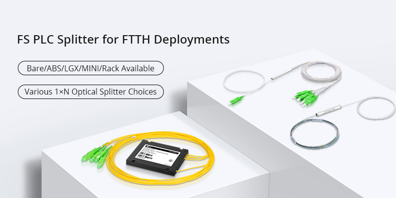
PLC splitter is a simple passive component which plays an important role in the applications of technologies like GPON, EPON and BPON. It allows a strand of fiber optic signal being equivalently splitted into several strands of optical signal, which can support a single network interface to be shared by many subscribers. When selecting it, split ratios should always be considered. However, with the network cabling environment becoming increasingly complex, various PLC splitters with different package form factors are being invented. Now the package form factor of it is also a key factor to be considered. This post will introduce the most commonly used PLC splitters in different package form factors for your reference during selection.

Bare Fiber PLC Splitter

Bare fiber PLC splitter is commonly used in FTTx projects. It leaves bare fiber on all its ends. Thus, they can be spliced by network engineer freely according to the applications. Meanwhile, it requires the least space during cabling. They can be installed in fiber optic splicing closure easily to provide FTTH signal distribution.

blockless bare fiber PLC splitter

Blockless PLC Splitter

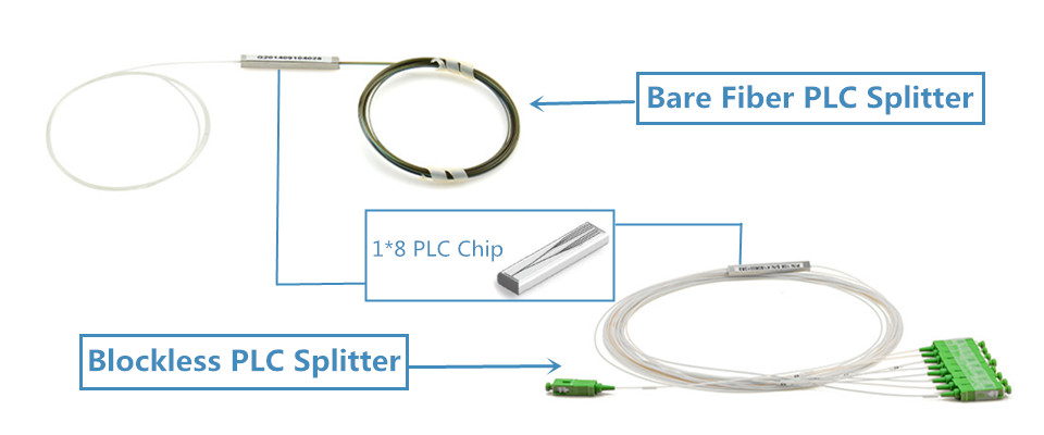
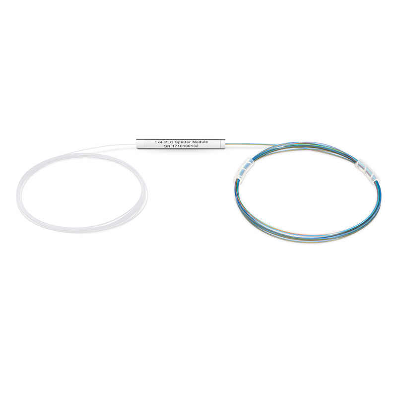
A blockless PLC splitter looks like a bare fiber splitter. The main differences are that the blockless one is usually terminated with fiber optic connectors and it uses a compact stainless tube package. It is also common that many bare fiber PLC splitters also use stainless tube package for the split chip.

Fanout PLC Splitter

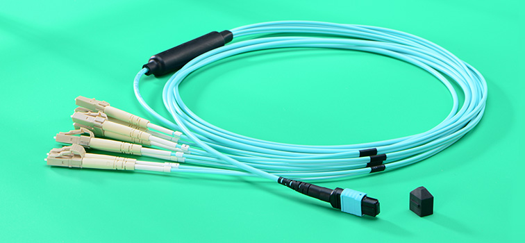
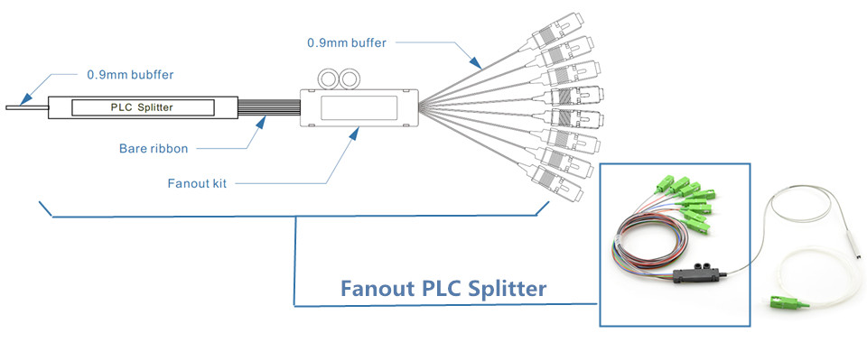
Fanout PLC splitter generally uses 0.9mm buffer fiber, added with a length of ribbon fiber terminated with fanout kit behind the PLC split chip. The splitter ratios of it also come in various types. The following picture shows a 1:8 fanout version which is terminated with SC/APC connectors.

fanout PLC splitter

ABS PLC Splitter

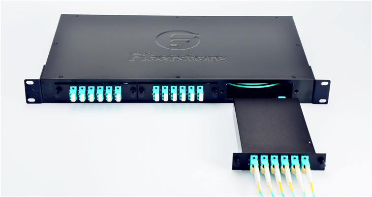
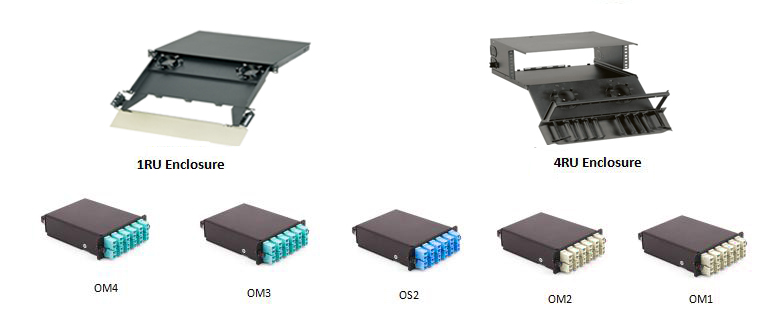
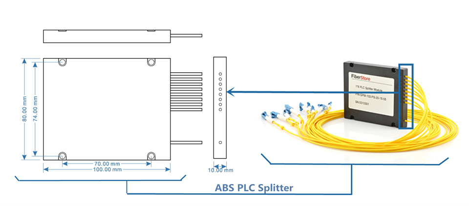
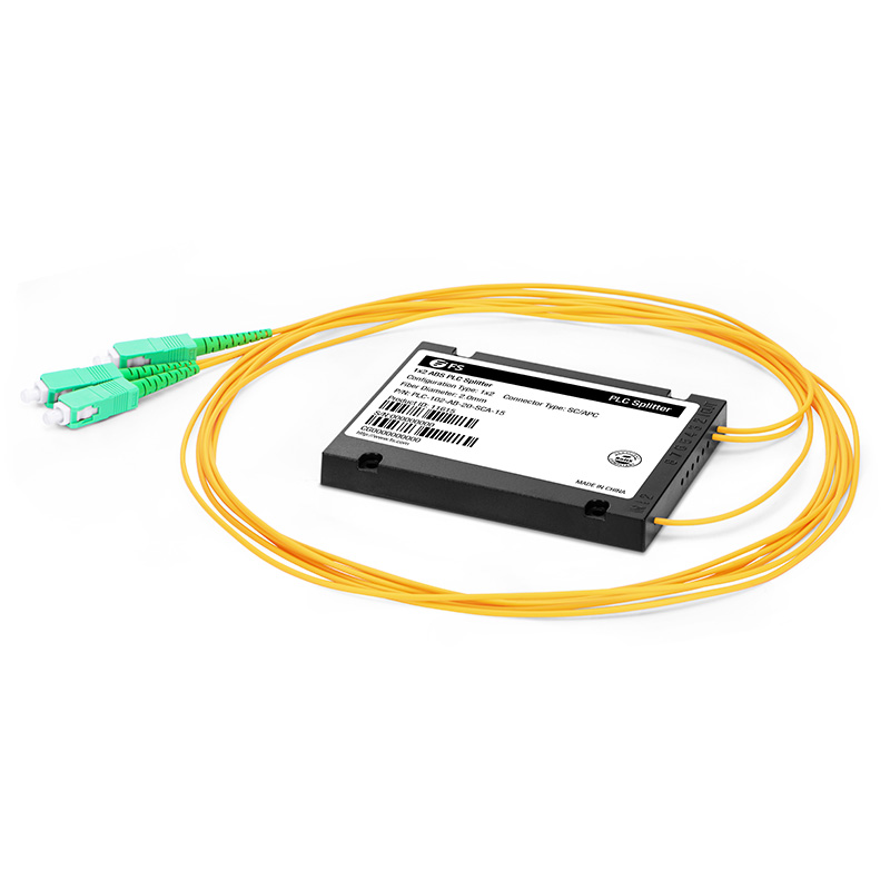
ABS PLC splitter uses ABS plastic box to holding the splitter chip. The inbound fibers and distribution fibers are arranged on the same plate of this ABS box, which can provide easier and more flexible cabling. Except providing reliable protection, it can also be installed in a variety of boxes or enclosures. It is very commonly to install a it in a standard 19-inch rack unit.

ABS PLC splitter

LGX Box PLC Splitter

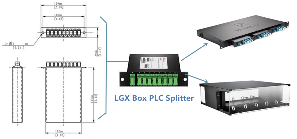
LGX Box PLC splitter looks like an MTP LGX cassette. It houses the whole splitter inside a metal box and leave fiber optic adapters for both inbound fibers and distribution fibers on its front panel. The LGX splitter can be used stand alone or be installed in the standard rack unit or fiber enclosures for better cabling.

LGX PLC splitter

Mini Plug-in PLC Splitter

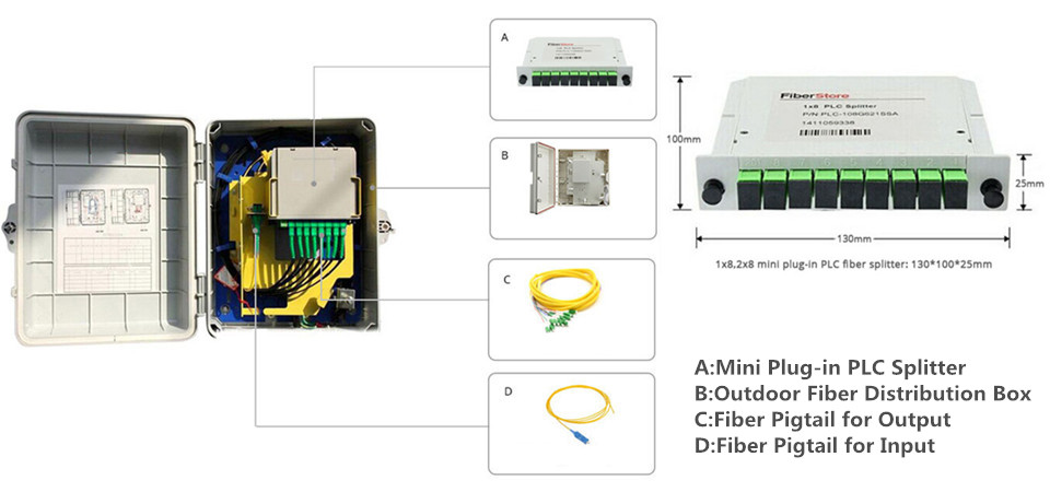
Mini plug-in PLC splitter is now widely used in FTTx project, especially at the distribution points near the end users of the FTTx networks. It provides fast installation and low space requirement helping to alert the deployment of FTTs projects. Fiber pigtails for input and output can be directly connected with this passive component easily.

mini plug-in PLC splitter

Tray Type PLC Splitter

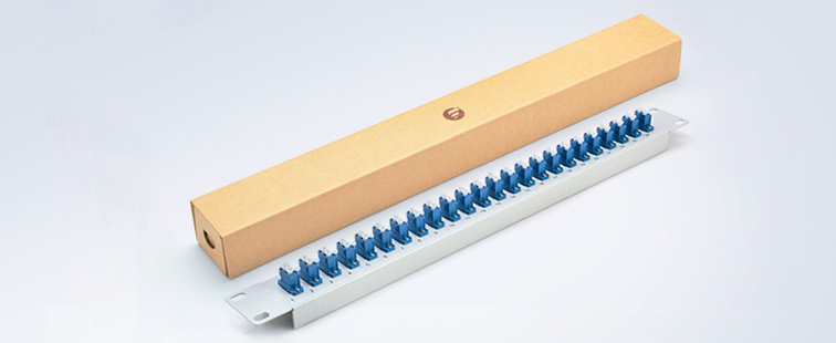
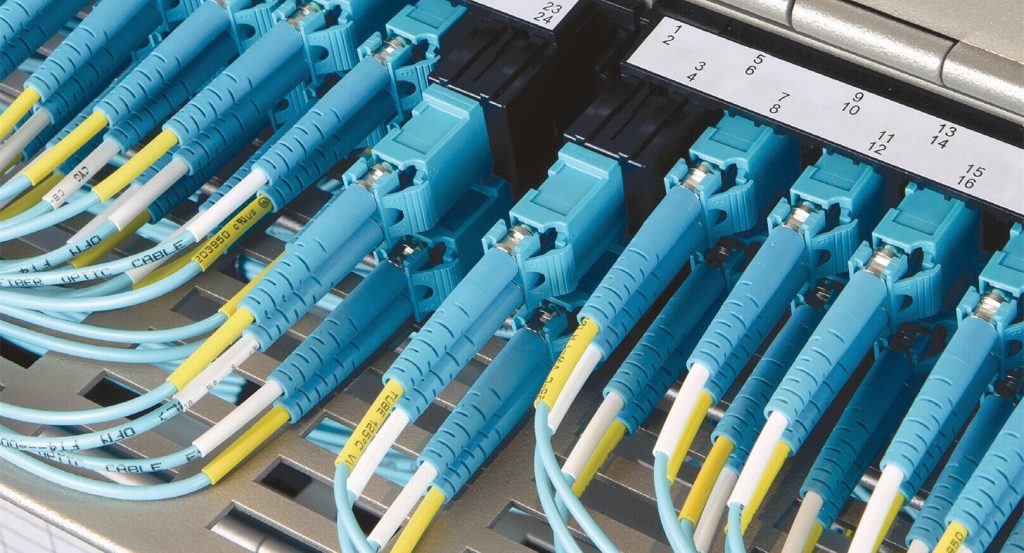
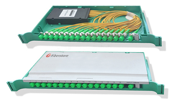
Tray type PLC splitter also uses a space saving package form factor for better cable management. However, it uses a international 19-inch design which can be deployed in ODF for compact cable management and signal distribution. With this design, the ports on tray type splitter are clearly marked, which can reduce the faults caused by wrong connections.

tray type PLC splitter

Rack Mount PLC splitter

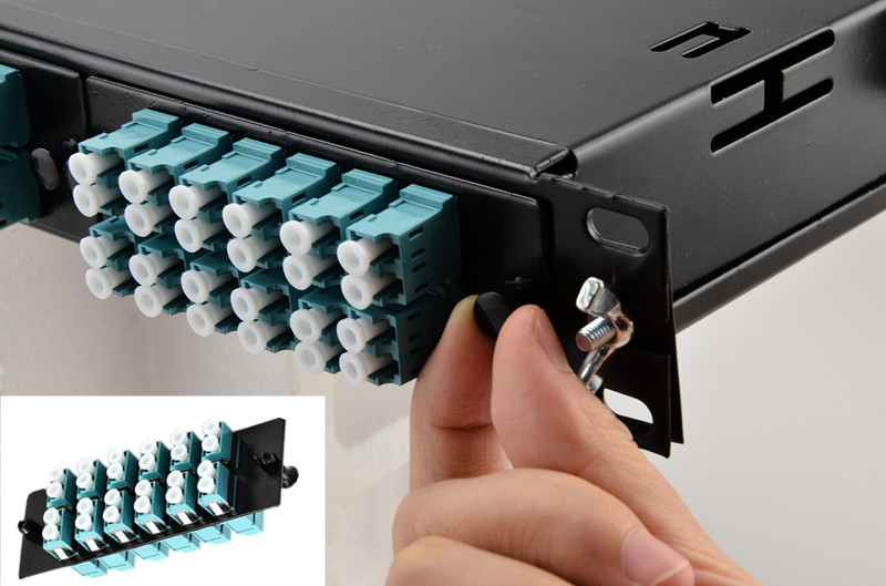
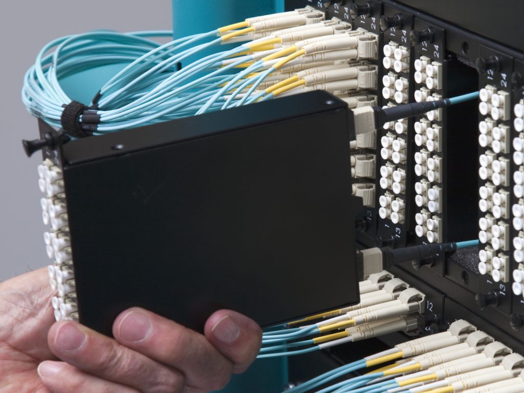
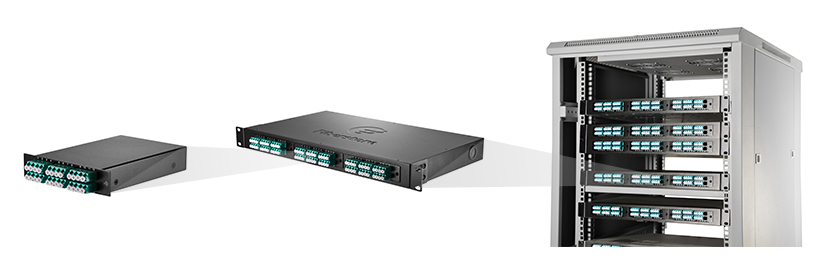
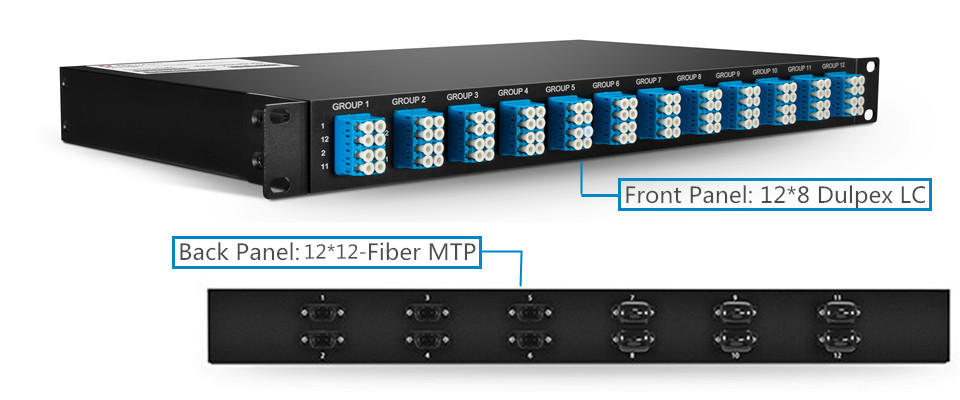
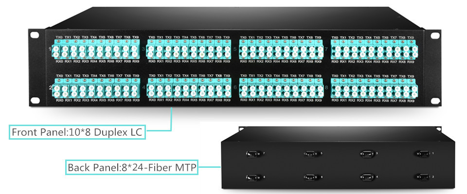
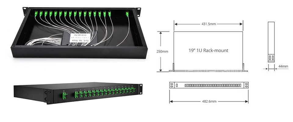
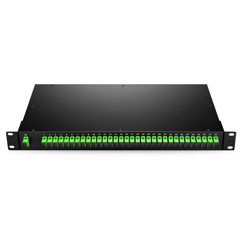
Rack mount PLC splitter is designed to meet the requirement of high cabling density for data centers or server room. It can be firmly installed on the data center or server racks. It is an ideal solution for high density cabling environment. FS.COM can provide PLC splitter ports up to 64 in 1U 19-inch rack. The following picture shows the details of a 1:8 rack mount one provided in FS.COM.

rack mount PLC splitter

FS.COM PLC Splitter Solution

PLC splitter is a cost-effective passive optical component enabling a single network interface to be shared by two or more users. Selecting the right package form factor for it can help a lot during both the network deployment and maintaining. Most of the above mentioned splitters in different package form factors are all being provided in FS.COM. Customized ones are also available in FS.com. Kindly contact sales@fs.com for more details if you are interested.

Source:

How Many Fiber Optic Splitter Types Are There? – FS Community


How to Connect 40G QSFP+ SR4 Transceivers to Network

40G network is gradually being applied in today’s backbone transmission network, during which long distance transmission is required. 40G QSFP+ SR4 fiber optic transceiver is being widely applied for 40G transmission in short distances. Generally, 40G QSFP+ SR4, working on wavelength of 850 nm, can support 40G fiber optic transmission a distance up to 150 m over OM4 multimode optical fiber. Inserted in switch, QSFP+ SR4 module utilizes a MTP/MPO interface for dual way transmission. There are a lot of methods to connect QSFP+ SR4 transceivers with other devices for different applications, by using different connectivity products. In addition, the cabling for 40G is relatively more difficult than that of 10G network, which requires more cables and spaces. The following will introduce several high density QSFP+ SR4 transceiver cabling methods.

QSFP+ SR4 40G to 40G Applications

40G to 40G transmission is needed in a 40G fiber optic network. The following picture simply illustrates how 40G to 40G multimode transmission is being achieved by QSFP+ SR4 transceivers. Two QSFP+ SR4 modules are separately inserted in two 40G switches. Then the two transceiver are connected by a length of multimode MTP trunk cable. This is the simplest way to use QSFP+ SR4 transceiver.

40G cabling

In some cases, there are lot of 40G connections required at the same time and same places, which means the increasing of both cable count and cabling difficulty. For better cable management and higher density cabling, a 48-port 1U rack mount MTP fiber patch enclosure can be used as shown in the following picture. Up to four 12-port MTP fiber adapter panels can be deployed in this standard 1U rack mount enclosure. With the help of this 48-port MTP fiber enclosure, cable management for 40G connections could be easier.

40G to 40G cabling

QSFP+ SR4 40G to 10G Applications

QSFP+ SR4 is a parallel fiber optic transceiver which means it uses four fibers for transmitting and four fibers for receiving at the same time. The 40G fiber optic signal can be separated into four 10G signals to meet the 40G to 10G transferring requirements. The fiber optic cable count will be increased at the 10G distribution end. Usually a breakout MTP-8LC harness cable is used. For better cable management, a 1U 96-fiber enclosure is recommended, which includes four HD MTP cassettes transferring MTP front the 40G end to LC at the 10G end. Four 10G-SR SFP+ modules, inserted in 10G switch/ports, can be connected to the corresponding LC ports on this fiber enclosure to achieve the duplex transmission between 40G and 10G.

40G to 10G cabling

For higher cabling density, the above mentioned 48-port 1U rack mount MTP fiber patch enclosure is still being recommended, which can provide high density 40G MTP cabling environment. And additional MTP-8LC harness cables should be used for transferring signals between 40G and 10G (shown in the following picture).

40G to 10G high density cabling

Conclusion

Depending on its parallel transmission mode, QSFP+ SR4 modules can meet a variety of cabling applications with great flexibility. The above methods is just several commonly used ones, detailed cabling methods for QSFP+ SR4 modules are depended on the practical applications and cabling environments. Related products for the above mentioned methods are listed in the following tables. Kindly visit FS.COM or click the attached links for more details. You can also contact sales@fs.com for more information about 40G cabling.

Products Description
40G QSFP+ SR4 Module 40GBASE-SR4 QSFP+ 850nm 150m MTP/MPO DOM Transceiver
10G-SR SFP+ Module 10GBASE-SR SFP+, 850nm 300m, MMF, LC duplex
MTP Trunk Cable 12 Fibers OM4, 12 Strands MTP Female to Female, Polarity Type B
MTP-LC Harness Cable 8 Fibers OM4, 12 Strands MTP Harness Cable, Polarity Type B
LC-LC Fiber Patch Cable 1~100M LC-LC Duplex 10G OM4, MMF Fiber Patch Cable
96 Fibers Rackmount Fiber Enclosure 96 Fibers 1U Rackmount Fiber Enclosure loaded with 4 MTP HD Cassettes 2x MTP-12 to Duplex LC/UPC 10G OM4
48 Ports MTP Fiber Enclosure 1U Rackmount FHD Series Fiber Enclosure, Loaded with 4 FAPs (12xMTP)

Which Fiber Enclosure Fits Your Data Center Application?

Fiber enclosure, providing solid fiber optic links protection and easy & fast cable management, is becoming a must-have component in data center and server room fiber cabling. As data center cabling requirements are various, fiber enclosures also have a lot of designs. Selecting the right fiber enclosures can largely increase the working efficiency and decrease the costs of labor and time. Which fiber enclosure knows fits your data center requirements best? Here will introduce several most commonly used and affordable fiber enclosures that are used for data center cabling.

Fiber Enclosure Overall Design

There are two widely used designs of fiber enclosures in general: wall mount fiber enclosure and rack mount fiber enclosure. The functions of the two types of fiber enclosures can be literally understood. Usually, a wall mount enclosure can be installed directly on a wall for fiber cabling. A rack mount enclosure usually has an industry standard 19 inch wide rack unit (RU) design and can be installed on a rack for fiber cabling. For higher fiber count, the rack mount fiber enclosure could be 2/4/6/12RU or more.

fiber enclosure

The rack mount fiber enclosure also has two versions in general. One is a fixed one with a lid which can be removed from the enclosure for fiber cabling, the other one is a slide-out fiber enclosure. Currently, the most popular rack mount fiber enclosure is usually has a slide-out design, which allows customers to remove the whole enclosure from the rack and provides easier internal fiber connection access.

rack mount fiber enclosure

Fiber Enclosures With Different Front Panel

The front panel of a fiber enclosure is also very important which can directly affect the fiber count that an enclosure can provide and the cabling methods. To fit various fiber cabling environments and network applications, the fiber enclosure front panels come in a variety of types. Here will introduces several most popular fiber enclosures with different front panel designs.

fiber enclosure front panel
Fiber Enclosure With Fixed Front Adapter Panel

A fixed front adapter panel is usually a 19 inch wide fiber adapter panel which can be installed on the fiber enclosure to accommodate various fiber optic connectors. The port number and fiber adapter type will determine the fiber count and connector types that can be installed with the fiber enclosures. The following picture shows a 1U fiber adapter panel loaded with 24 duplex LC adapters which can provide up to 48 fiber optic connections. This fiber adapter panel can be installed on fiber enclosure working as the front panel.

12-duplex LC fiber adapter panel
Fiber Enclosure With Removable Adapter Panels

Driven by the requirement for higher cabling density and flexible cabling methods, the front panel of a fiber enclosure could be composed by several individual fiber adapter panels which could be loaded with the same or different types of fiber optic adapters. Meanwhile, these individual fiber adapter panels can provide various types of adapters and higher cabling density. Generally, up to three 12 duplex LC port fiber adapter panels with industry standards can be installed on a 1U rack mount fiber enclosure. However, a smaller version of fiber adapter panel is also provided. Up to four 12 duplex port fiber adapter panels can be installed on a 1U rack mount fiber enclosure.

fiber optic adapter
Fiber Enclosure With Removable MTP/MPO Cassettes

The fiber adapter panel that installed on the fiber enclosures required additional internal fiber cabling, which usually uses fiber pigtails. As 40G/100G fiber networks which use MTP/MPO interfaces are gradually being deployed in today’s data center, the cabling methods become more complex. To simplify the cabling methods, MTP/MPO cassettes are being introduced to the market. Up to three LGX MTP/MPO cassettes can be installed on a 1U fiber panel enclosure. With these cassettes, the internal cabling of a fiber enclosure could be eliminated. For higher cabling density, there is also a high density cassette. Up to four of the HD MTP/MPO cassettes can be installed on a 1U fiber panel.

MTP/MPO cassette

Conclusion

The above-mentioned fiber enclosures are the most commonly used ones in today’s applications. The cabling environments of every data center are different. Finding the right fiber enclosure means a lot. Excepted standard fiber enclosures, there are also a lot of customized fiber enclosures that are provided in FS.COM. The customer can design their own fiber enclosures in FS.COM according to their own applications.

Pre-terminated Fiber Cabling in Data Center

pre-terminated fiber cabling

Fiber optic cabling and termination usually cost a lot of time and labor during the deployment of data center. Filed fiber optic termination is still being widely used in many data centers. However, with the data center increasingly depending on the high density cabling, fiber cabling and termination in data center becomes will cost more time and money if using the traditional field termination methods. Meanwhile, the fiber optic network is becoming more and more complex, which makes the data center cabling becomes more difficult. The risks of faults caused manual fiber termination will be increased. To solve problems caused by manual operations and meets the high density requirement of the data center, pre-termianted fiber cable assemblies are introduced in data center.

Advantages of Pre-Terminated Fiber Cable Assemblies

Deploying a data center by using field termination methods might need a few days or more. Engineers have to termination a lot of fiber optic links and connect them to the right ports. To ensure there are no wrong links and bad fiber optic splicing joints, a lot of checking should be done. However, pre-terminated fiber cable assemblies, using the plug-and-play designed modules and cables, can largely improve the working efficiency, increase cabling density and decrease the total data center installation cost. In addition, the factory terminated fiber cable assemblies eliminate the need of fiber optic splicing and provide higher performance compared with field terminated fiber optic cables.

MTP cassette application

Pre-Terminated Fiber Cabling Assemblies in 40G/100G Applications

The most commonly used pre-terminated fiber cabling assemblies for 40G/100G high density cabling applications are MTP/MPO fiber cable assemblies including MTP/MPO trunk cable, MTP/MPO harness cable and MTP/MPO cassette. These pre-terminated components can be directly connected to fiber optic network for data transmission. Making good use of these components can largely increase the cabling density and working efficiency in data centers.

MTP/MPO Trunk Cable

MTP/MPO trunk cable is a length of multi-fiber optical cable usually used for backbone transmission in data center. 12-fiber MTP/MPO trunk cable and 24-fiber MTP/MPO trunk cable used for 40G and 100G applications separately.

MTP/MPO trunk cable

There are generally two versions of MTP/MPO trunk cable—single-strand MTP/MPO trunk cable and multi-strand MTP/MPO trunk cable. A multi-strand MTP/MPO trunk cable combines several single-stand MTP/MPO trunk cables together. For example, a 72-fiber MTP/MPO trunk cable, as shown in the following picture, has 6 strands of 12-fiber cables combining together. Each strand is terminated with a 12-fiber MTP/MPO connector.

72-fiber trunk cable
MTP/MPO Harness Cable

MTP/MPO harness cable is a fanout version of MTP/MPO fiber optic cable. A MTP/MPO fiber optic connector is terminated on one end of this cable, the fanout end it terminated several other types of fiber optic connectors which are usually LC fiber connectors. This type of pre-terminated fiber optic cable is generally used for 40G to 10G transmission or 100G to 10G transmission. MTP/MPO harness cables also come into various types, the most commonly used are 12-fiber MTP/MPO to 6 duplex LC harness cable for 40G duplex transmission and 24-fiber MTP/MPO to 12 duplex LC harness cable for 100G duplex transmission.

MTP/MPO harness cable
MTP/MPO Cassette

MTP/MPO cassette is a specially designed box which contains one or more small version of MTP harness cables in side it. Generally there is one or more MTP fiber optic interface on the back rear of a MTP/MPO cassette and several LC interfaces on its front rear. It can be easily installed on the rack for easier cabling as shown in the following picture.

mtp-cassette-application

In this way, the fiber optic connections are protected in this box and more fiber optic connections can be added to the data center without worrying about space limitation. The most commonly used are MTP/MPO LGX cassettes. However, driven by increasing need for high density, the size of MTP/MPO Cassette is keeping decrease. HD MTP/MPO cassette (shown in the following picture) is also available in the market for higher cabling density.

HD MTP/MPO Cassette

Conclusion

The pre-terminated fiber cable assemblies help to accelerate the data center deployment, reduce costs and error, and provide great flexibility and scalability. MTP/MPO cabling system as one the most popular pre-terminated fiber cabling solutions can perfectly fit the 40G and 100G applications. The above mentions products is just a really small part of the pre-terminated fiber cable assemblies. If you need more details, please visit FS.COM where you can customize the pre-terminated fiber cable assemblies according to your applications.

Fiber Patch Panel for Ultra High Density Cabling

How to build a flexible and manageable cabling system in high density cabling environment is becoming an issue which has attracted increasing attention of many data centers. Cable management components like fiber patch panel have kept upgrading to meet the increasing needs for high density cabling. Proper using of patch panel does not only provide well management for fiber patch cables in data center, but also protects the fiber patch cables and reduces the risks of faults caused by problems like bend loss, dusts and wrong connections. For ultra high density cabling like 40G and 100G connections, things would be more complex. Luckily, with clever design of fiber patch panels, customers won’t worry about fiber cable mess and faults caused by bad cable management.

ultra high density cabling

Larger Fiber Count Means More Space Requirements

For 40G network, the backbone core signals are generally distributed into 4 strands of 10G signals in first. This process usually employs fanout MTP to LC fiber patch cables. For example, a 12-fiber MTP to 4 LC duplex fiber harness cable uses 8 fibers for 4 ways of duplex transmission. It means a fanout cable with a MTP connector and its 8 legs terminated with LC connector added in data center for a single duplex way of 40G transmission. In data center, a lot of 40G network should be built, which means the fiber cable count will be largely increased. Not to mention the 100G applications, which will increase at least 10 fibers for every 100G signal distribution.

Using Modular Design to Reduce the Space Requirements

To solve this problem, a series of fiber patch panels have been invented for 40G and 100G signal distribution applications. Here introduce two versions of ultra high density fiber patch panels which are designed for 40G and 100G applications separately: 1U 96-fiber MTP to LC breakout fiber patch panel and 2U 160-fiber MTP to LC breakout fiber patch panel. Both of them use the industry standard rack unit design, which can be installed on any standard rack.

96-fiber MTP to LC breakout fiber patch panel
1U 96-Fibers MTP-LC Fiber Patch Panel for 40G Applications

The above picture shows the details of this 96-fiber breakout patch panel. On the back panel of this unit, there are 12 8-fiber MTP adapters which are separately linked 12 groups of LC duplex adapters on the front panel. Each of the 12 groups has 4 duplex LC adapters which can support 4 ways of 10G duplex transmission. Thus, the whole fiber patch panel can support up to 12*40G transmission in duplex ways. To decrease the error connections, each port has been clearly identified by numbers and groups.

160-fiber MTP to LC breakout fiber patch panel
160-Fiber MTP-LC Fiber Patch Panel for 100G Applications

A 160 fibers MTP to LC fiber patch panel uses a standard 2U rack design, which uses the same theory of the above mentions 96-fiber 40G fiber patch panel. The distribution of the 100G signals is generally achieved in 10*10G. There are 8 24-fiber MTP adapters on the back panel of this 100G fiber patch panel. Each of them connects a 24-fiber MTP adapter on the back panel to a group of 10 duplex LC adapters on the front panel. Thus, 8*100G duplex transmissions can be achieved with this 2U rack.

Conclusion

The above mentioned 1U 96-fibers MTP-LC patch panel for 40G and 160-fiber MTP-LC fiber patch panel for 100G applications do not only decrease the space requirement for ultra high density cabling environment, but also decrease the faults caused by cable clutter, connection, disconnecting or bend loss by protecting the optical fiber in side a strong and reliable box. Kindly visit FS.COM or contact sales@fs.com for more details about ultra high density patch panels, if you are interested.

Related articles: Best Patch Panel Cable Management Techniques

                             Fiber Optic Patch Panel Best Practices