
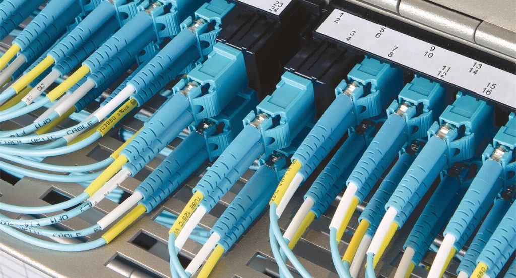
How to build a flexible and manageable cabling system in high density cabling environment is becoming an issue which has attracted increasing attention of many data centers. Cable management components like fiber patch panel have kept upgrading to meet the increasing needs for high density cabling. Proper using of patch panel does not only provide well management for fiber patch cables in data center, but also protects the fiber patch cables and reduces the risks of faults caused by problems like bend loss, dusts and wrong connections. For ultra high density cabling like 40G and 100G connections, things would be more complex. Luckily, with clever design of fiber patch panels, customers won’t worry about fiber cable mess and faults caused by bad cable management.
For 40G network, the backbone core signals are generally distributed into 4 strands of 10G signals in first. This process usually employs fanout MTP to LC fiber patch cables. For example, a 12-fiber MTP to 4 LC duplex fiber harness cable uses 8 fibers for 4 ways of duplex transmission. It means a fanout cable with a MTP connector and its 8 legs terminated with LC connector added in data center for a single duplex way of 40G transmission. In data center, a lot of 40G network should be built, which means the fiber cable count will be largely increased. Not to mention the 100G applications, which will increase at least 10 fibers for every 100G signal distribution.
To solve this problem, a series of fiber patch panels have been invented for 40G and 100G signal distribution applications. Here introduce two versions of ultra high density fiber patch panels which are designed for 40G and 100G applications separately: 1U 96-fiber MTP to LC breakout fiber patch panel and 2U 160-fiber MTP to LC breakout fiber patch panel. Both of them use the industry standard rack unit design, which can be installed on any standard rack.
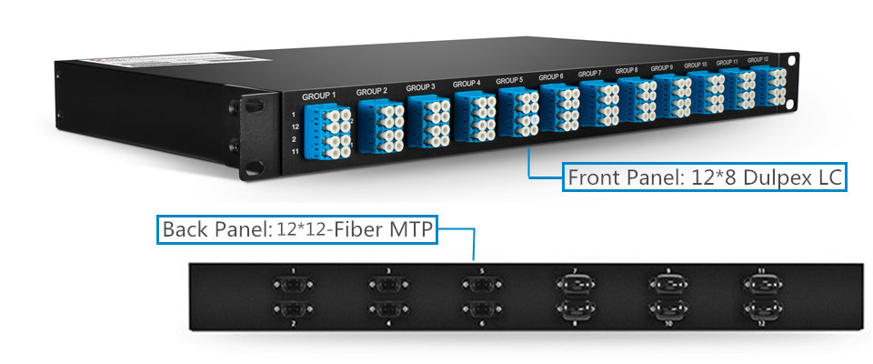
1U 96-Fibers MTP-LC Fiber Patch Panel for 40G Applications
The above picture shows the details of this 96-fiber breakout patch panel. On the back panel of this unit, there are 12 8-fiber MTP adapters which are separately linked 12 groups of LC duplex adapters on the front panel. Each of the 12 groups has 4 duplex LC adapters which can support 4 ways of 10G duplex transmission. Thus, the whole fiber patch panel can support up to 12*40G transmission in duplex ways. To decrease the error connections, each port has been clearly identified by numbers and groups.
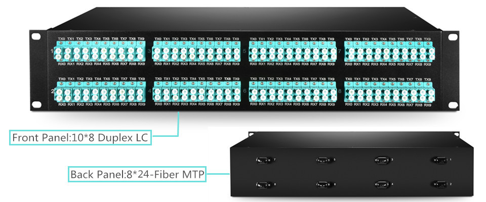
160-Fiber MTP-LC Fiber Patch Panel for 100G Applications
A 160 fibers MTP to LC fiber patch panel uses a standard 2U rack design, which uses the same theory of the above mentions 96-fiber 40G fiber patch panel. The distribution of the 100G signals is generally achieved in 10*10G. There are 8 24-fiber MTP adapters on the back panel of this 100G fiber patch panel. Each of them connects a 24-fiber MTP adapter on the back panel to a group of 10 duplex LC adapters on the front panel. Thus, 8*100G duplex transmissions can be achieved with this 2U rack.
The above mentioned 1U 96-fibers MTP-LC patch panel for 40G and 160-fiber MTP-LC fiber patch panel for 100G applications do not only decrease the space requirement for ultra high density cabling environment, but also decrease the faults caused by cable clutter, connection, disconnecting or bend loss by protecting the optical fiber in side a strong and reliable box. Kindly visit FS.COM or contact sales@fs.com for more details about ultra high density patch panels, if you are interested.
Related articles: Best Patch Panel Cable Management Techniques