Category Archives: Optical Transceiver Solution

Understand 100G Ethernet Standards

People want 100G Ethernet, meanwhile, they want to reduce the cost and increase the port density to the most. Driven by the combination of elements like that, 100G Ethernet standards and related optical transceivers have improved a lot in the past few years. As so many 100G Ethernet standards and package form factors are used, people might be confused by them easily. This post offers a detailed introduction about 100G Ethernet standards.

100G LR4 QSFP28

The first 100G Ethernet standard was approved in 2010. After that tremendous changes have happened in 100G technology in many aspects. The first generation of the 100G standards use the 10x10G lane in electrical signaling. For media signaling, some use 10x10G and some use 4x10G. The second generation 100G Ethernet standards apply 4x10G signaling for both electrical and media. In terms of transmission distances, different standards can support different transmission distance. Now there are more choices for transmission distances ranging from 1 meter to 40 kilometers. Meanwhile, the package form factors also changed a lot. The first 100G transceivers CFP is much larger than that of the new one QSFP28. To offer an intuitive way to illustrate these 100G Ethernet standards, I will list them in the following table.

Name Distance Media Type Module Type Media Signaling Electrical Signaling Standard
100GBASE-KP4 1m Backplane Backplane 4×25 4×25 June 2014
IEEE 802.3bj
100GBASE-KR4 1m Backplane Backplane 4×25 4×25 June 2014
IEEE 802.3bj
100GBASE-CR4 5m Twinax
Copper
CFP2, CFP4
QSFP28
4×25 10×10 June 2014
IEEE 802.3bj
100GBASE-CR10 7m Twinax
Copper
CXP, CFP2
CFP4, QSFP28
10×10 4×25 June 2010
IEEE 802.3ba
100GBASE-SR4 OM3:
70m
OM4:
100m
Parallel
MMF
CFP2, CFP4
CPAK, QSFP28
4×25 10×10 March 2015
IEEE 802.3bm
100GBASE-SR10 OM3:
100m
OM4:
150m
Parallel
MMF
CFP, CFP2, CFP4
CPAK, CXP
10×10 10×10 June 2010
IEEE 802.3ba
10×10-2km 2km Duplex
SMF
CFP 10×10 10×10 March 2011
10×10 MSA
10×10-10km 10km Duplex
SMF
CFP 10×10 10×10 August 2011
10×10 MSA
100GBASE-LR4 10km Duplex
SMF
CFP, CFP2, CFP4
CPAK, QSFP28
4×25 10×10 June 2010
IEEE 802.3ba
10×10-40km 40km Duplex
SMF
CFP 10×10 10×10 August 2011
10×10 MSA
100GBASE-ER4 40km Duplex
SMF
CFP, CFP2 4×25 10×10 June 2010
IEEE 802.3ba

The above table contains the 100G standards that published by IEEE and MSA, which are listed by the transmission distance from the top to the bottom. According to reports from many marketing reports, 100G optical component market will surge in 2016. FS.COM provide 100G solutions including transceivers, patch cable, cable management products, etc. Kindly contact sales@fs.com or visit FS.COM for more details about 100G Ethernet and products, if you are interested.

Related Article: 100G Ethernet Is Gaining Broader Market

10G SFP+ Transceiver Modules and Patch Cords Selection Guide

10G connection in telecommunication network is gradually moving from the backbone to layer 2 and layer 3. Both technology and market of 10G SFP+ transceiver modules are mature: the 10G transceiver modules have advanced from XENPAK which is the first generation of 10G transceiver to SFP+ which is now the most popular 10G optics. In addition, the price of 10G modules is getting lower. 10G modules are becoming affordable. Some genius guys even buy 10 SFP+ modules online to DIY private point to point 10G network. This article will offer basic information about 10G SFP+ transceiver modules and their connection instructions.

Basic of 10G SFP+ Transceiver Module

10G SFP+ transceiver has the same form factor of Gigabit SFP transceiver. Thus, many 10G modules can support 1/10G data rate to increase its flexibility during practical using. A SFP+ transceiver usually has two LC ports (as shown in the following picture). While 10G BiDi SFP+ transceiver, which transmitting and receiving signals from the same fiber optic cable, only has one LC port.

10G SFP+ transceiver and duplex patch cable

Except fiber optical transceivers, there are also various factory terminated copper-based or fiber optic based cables which are terminated with a SFP+ module on each end of the cable. There are mainly three types of these 10G cables: 10G SFP+ passive direct attached copper cable, 10G active direct attached copper cable and 10G SFP+ active optical cable. These 10G SFP+ cables eliminate the used of additional patch cable and can be directly plugged into the 10G SFP+ ports on switches. It is acceptable that these cables are an cost-effective and reliable solutions for 10G connections in short distance.

Optical Standards of 10G SFP+ Transceiver

According to IEEE standards, there are a variety 10GBASE SFP+ transceivers. For short distance transmission, 10GBASE-SR SFP+ and 10GBASE-LRM SFP+ can support transmission distance up to 300 meters and 220 meters over multimode fiber optic cables separately. 10GBASE-SR SFP+ modules is the most commonly used transceiver for short distance. It is suggested to work over wavelength of 850 nm.

There are a lot of 10G SFP+ transceivers that support long distance, like 10GBASE-LR SFP+, 10GBASE-ER SFP+, 10GBASE-ZR SFP+, CWDM SFP+, DWDM SFP+, BiDi SFP+, etc. These transceivers can support transmission distances ranging from 10 km to 120 km over single-mode fiber optic cables.

There is another special type of 10G transceivers which has been mentioned in this post, which is known as dual-rate SFP+. For example, dual-rate 1000BASE-LX and 10GBASE-LR SFP+ transceiver can be adjusted to support both 1G and 10G data rate up to 10 km over wavelength of 1310 nm.

10G BiDi SFP+ and simplex patch cable

Fiber Patch Cable Selection Guide for 10G SFP+ Transceivers

As 10G SFP+ DAC and AOC eliminate the using of additional patch cords. This part will introduce the selection guide for 10G SFP+ transceivers. During the selection of fiber optic patch cables for 10G SFP+ transceivers, the transmission distance is the first element to be considered. Single-mode patch cable is used for long distance transmission and multimode is designed for short distance transmission. Then the ports on the transceiver for receiving and transmitting should be considered. As mentioned, most 10G transceiver use duplex LC port, while BiDi SFP+ use simplex port (as shown in the above picture). Thus, simplex LC patch cords or duplex LC patch cords are used according to the port type on the transceiver. The following chart introduces detailed cabling information for 10G SFP+ transceivers.

10G SFP+ Transceivers Cabling Solution
Optical Standards Cable Type Distance
10GBASE-SR SFP+ LC duplex, MM 300 m
10GBASE-LRM SFP+ LC duplex, MM 200 m
10GBASE-LR SFP+ LC duplex, SM 10 km
10GBASE-ER SFP+ LC duplex, SM 40 km
10GBASE-ZR SFP+ LC duplex, SM 80 km
10GBASE-BX SFP+ LC simplex, SM 80 km
CWDM SFP+ LC duplex, SM 120 km
DWDM SFP+ LC duplex, SM 80 km
Dual-Rate 1000BASE-LX/10GBASE-LR LC duplex, SM 10 km
Dual-Rate 1000BASE-SX/10GBASE-SR LC duplex, MM 300 m

This post just introduced the basic information of 10G optics and cabling information. For more specific information, please visit FS.COM, where you can find a variety of 10G SFP+ optics modules.

Cable and Optics Solution for Catalyst 4948E and Catalyst 4948E-F Switches

Catalyst-4849E-F switch

Cisco Catalyst 4900 series switches were once the most widely deployed ToR (top-of-rack) switches in this industry. This post will introduce the detailed cabling information for two upgrade version of this series switches, which are Cisco Catalyst 4948E and Catalyst 4948E-F. Compared with Catalyst 4900 series switches, the two switches double the uplink bandwidth and provide nonblocking server-to-server traffic with 176G aggregate throughput. Meanwhile, they provide true front to back and back to front airflow with no side or top venting, which can largely reduce the cooling burden of the data centers.

Port Information of Catalyst 4948E and Catalyst 4948E-F

Cisco Catalyst 4948E and Catalyst 4948E-F are very alike. The main difference of the two switches is that the air flow in the Catalyst 4948E goes from the front to the rear of the switch while in Catalyst 4948E-F switch the air flow goes from the rear to the front. The front panel of the two switches is generally the same. Both of the two switches are one-rack-unit (1RU) fixed configuration switch with 48 RJ45 ports of 10/100/1000M for downlink and 4 SFP/SFP+ ports of 1/10G for uplink on the front panel. The following picture shows the detailed port information of Cisco Catalyst 4948E and 4948E-F switch.Catalyst 4948E-F ports information

Downlink Connection for Cisco Catalyst 4948E and Catalyst 4948E-F

The 48 ports on the front panel of Catalyst 4948/4948E-F can support downlink of 10/100/1000M. The great advantage of these ports is that they can configure themselves to operate at the speed of the attached devices. If the attached devices do not support auto-negotiation, the speed and duplex parameters can be set explicitly. A network cable with a RJ-45 plug at both end can connect Cisco Catalyst 4948E/4948E-F switch to the downlink target devices.

Uplink Connection for Cisco Catalyst 4948E and Catalyst 4948E-F

The four uplink SFP/SFP+ ports on Cisco Catalyst 4948E and Catalyst 4948E-F can support both copper and fiber optic transmission of 1G/10G by using different modules and cables. In addition, these ports can also support CWDM SFP transceivers and DWDM SFP transceivers. The following part will introduce the details about how to connect Cisco Catalyst 4948E/4948E-F to 1G network and 10G network.

For 1G connection based on cooper, the 1000BASE-T can be used with RJ45 connector and Cat5 cable. For 1G connection based on fiber optic, there are a wide range of SFP transceivers can be used. Different SFP transceivers should be used with appropriate cables to ensure its best performance. For example, CWDM and DWDM SFP transceivers is usually used with LC connector and single-mode fiber optic cable, thus they can support long distance transmission. The following table presents the solutions for Cisco Catalyst 4948E/4948E-F 1G uplink connection.

Modules Connector & Cable Distance
GLC-T (1000BASE-T) RJ45,Cat5 100m
GLC-SX-MM LC duplex, MMF 550m
GLC-SX-MMD 550m
GLC-LH-SM LC duplex, SMF 10km
GLC-LH-SMD 10km
GLC-EX-SMD 40km
GLC-ZX-SM 70km
GLC-ZX-SMD 70km
CWDM SFP 40-120km
DWDM SFP 40-120km
GLC-BX-D LC simplex, SMF 10km
GLC-BX-U 10km
GLC-BX40-D-I 40km
GLC-BX40-U-I 40km
GLC-BX40-DA-I 40km
GLC-BX80-U-I 80km
GLC-BX80-D-I 80km

For 10G connection, both transceiver and DAC (direct attach cable) can be used, according to the transmission distance requirements. Generally, 10G SFP+ to SFP+ DAC can support transmission distance around 10 meters. If transmission distances are up to hundreds meters or kilometers, fiber optic transceivers should be used. The following table is the detailed solution for Cisco Catalyst 4948E/4948E-F 10G uplink connection.

Modules Connector & Cable Distance
SFP-10G-LRM LC duplex, MMF 220m
SFP-10G-SR 300m
SFP-10G-SR-S 300m
SFP-10G-LR LC duplex, SMF 10km
SFP-10G-LR-S 10km
SFP-10G-ER 40km
SFP-10G-ER-S 40km
SFP-10G-ZR 80km
SFP-10G-ZR-S 80km
DWDM SFP+ 40-80km
SFP-10G-BXD-I LC simplex, SMF 10km
SFP-10G-BXU-I 10km
SFP-10G-BX40D-I 40km
SFP-10G-BX40U-I 40km
SFP-H10GB-CU1M 10G SFP+ DAC Twinax Cable 1m
SFP-H10GB-CU3M 3m
SFP-H10GB-CU5M 5m

Please contact sales@fs.com or visit FS.COM for more details about the compatible transceivers and DACs for Cisco Catalyst 4948E and Cisco Catalyst 4948E-F switches.

Source: http://www.fs.com/blog/catalyst-4948e-catalyst-4948e-f-cabling-solutions.html

How to Take Full Advantages of Switches in Data Center: A Case Study of IBM G8264 Switch

During data center upgrading or migration to higher data rate like 40G/100G, the network designer is always pursuing for flexibility. This is because devices or cabling components with great flexibility can not only decrease the cost for upgrading, but also provide more possibilities for the data center in the future. Switch has always been the most important device data center. Thus, a flexible switch should support a variety of transmission media and data rates, which could have significant positive influence during data center upgrading on cabling and costs. IBM G8264 switch is such a switch that is specially designed for data center, which is suggested to be used at layer 2 or layer 3, providing non-blocking line-rate, high-bandwidth switching, filtering, and traffic queuing without delaying data. However, to make full use of these switches, you should select proper connection components and cabling plans. This post will take IBM G8264 switch as an example to illustrate how to take full advantages of the switches in data center.

Understand Your Switch—IBM G8264 Switch

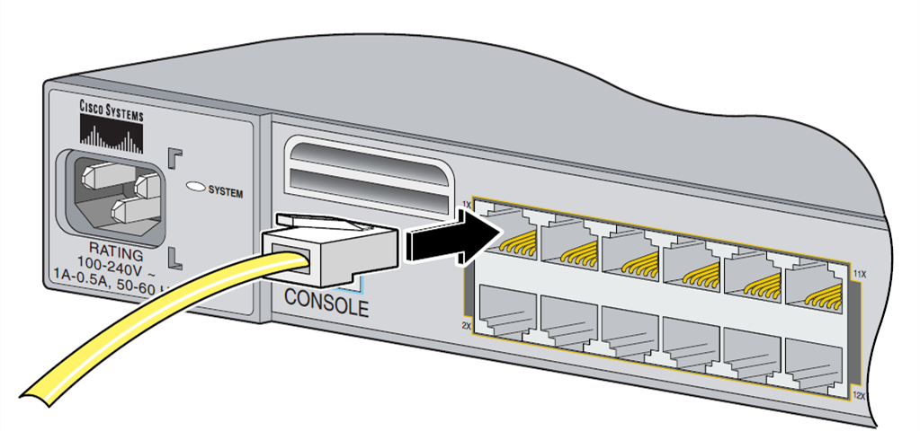
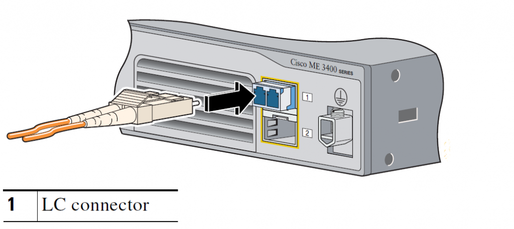
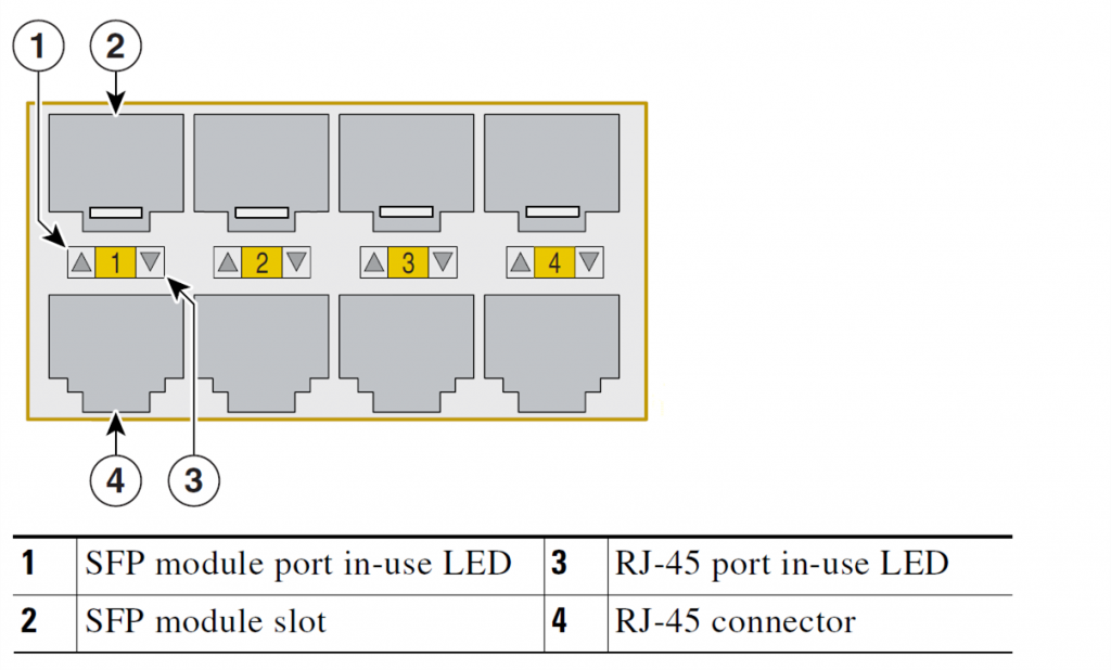
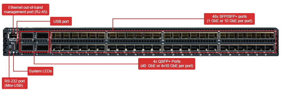
The first step to make full use of a switch is to have a full understanding of the switch you are using. There are many ways to understand your switch. While the most direct method is to understand the ports on the switches. This method also works for IBM G8264 switches. As shown in the following picture, which is the front panel of IBM G8264 switch, the most outstanding part of the switch is the 48 SFP/SFP+ ports. It occupied most space on IBM G8264 switch front panel. These ports can support data rate of 1G/10G. Four QSFP+ ports for 40G are beside these SFP/SFP+ ports. There are three another ports for other use on the from panel: one 10/100/1000 Ethernet RJ45 port for out of band management, one USB port for mass storage device connection and one mini-USE console port for serial access.

IBM G8264 switch port information

IBM G8264 Connection in Data Center

It is clear that IBM G8264 switch can support data rate of 1G, 10G and 40G. The following parts illustrate how to connect IBM G8264 with the target devices in 1G, 10G, and 40G network separately in details. During the cabling in data center, distance is always a factor that cannot be ignored. The transmission distance required, can largely decide the cabling components selection.

1G Connection of IBM G8264 Switch

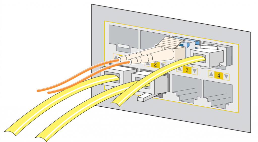
To accomplish the 1G connection of IBM G8264 switch and target devices, there are several methods according to transmission distance and transmission media (fiber optic or copper). For distance up to 100 meters, RJ-45 1000BASE-T SFP transceivers with UTP Cat5 cables are suggested, cause they are based on copper and is cheaper than fiber optic components. However, if you want reach a longer distance with good transmission quality, it would be better to use fiber optic cable and optical transceiver. By using 1000BASE-SX SFP optical transceivers with multimode fiber, the transmission distance is up to 220 (62.5 μ multimode fiber) meters and 550 meters (50 μ multimode fiber). For long distance transmission, single-mode fiber optic cables are suggested to be used with 1000BASE-LX SFP optical transceivers, which can connect IBM G8264 switch with the target devices that are 10 kilometers far away. The following chart is the detailed product solutions for IBM G8264 1G connection.

Transmission Media Module Cable & Connector Distance
Copper Cable BN-CKM-S-T: SFP 1000BASE-T copper transceiver RJ45, Cat5 cable 100 m
Fiber Optic Cable BN-CKM-S-SX: SFP 1000BASE-SX optical transceiver LC duplex, MMF 220 m(50μ multimode fiber)
550 m(62.5μ multimode fiber)
BN-CKM-S-LX: SFP 1000BASE-LX optical transceiver LC duplex, SMF 10 km

10G Connection of IBM G8264 Switch

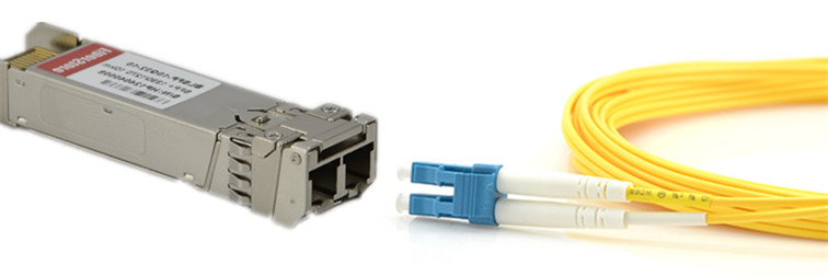
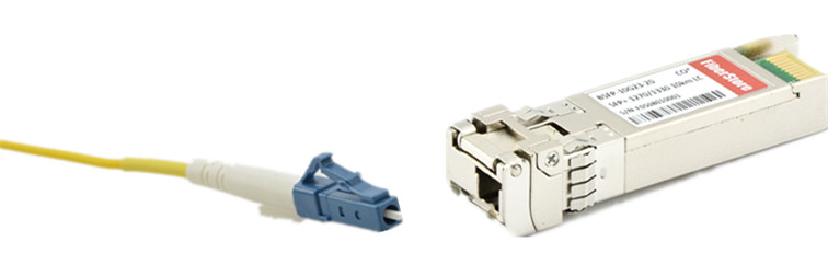
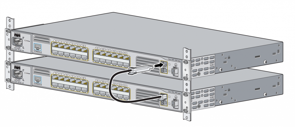
As mentioned, IBM G8264 switch supports 10G configuration. For 10G, there are mainly two methods: using DACs (direct attach cables) or using transceivers and patch cords. The beauty of using DAC is the eliminating of transceivers and reduction of cost. However, the transmission distance is limited to 7 meters by using DACs. If longer distances are required, 10GBASE-SR transceiver used with OM3 multimode fiber can support transmission distance up to 300 meters. If 10GBASE-SR transceiver is used with OM4 fiber optic cable, distance up to 400 meters could be reached. Using 10GBASE-LR transceiver with single-mode fiber optic cable, IBM G8264 switch can be connected with target devices that are 40 kilometers away.

IBM G8264 switch and 40GBASE QSFP+ transceiver

If the 10G ports number cannot satisfy the requirements, the one QSFP+ port on IBM G8264 can be split into four 10G ports, by using QSFP+ DAC breakout cables for distances up to 5 meters. For distances up to 100 meters, optical MTP-to-LC break-out cables can be used with the 40GBASE-SR4 transceiver. Kindly check the following table for IBM G8264 switch 10G cabling components solutions.

Data Rate Modules Cable & Connector Distance
10G-10G Connection BN-SP-CBL-1M: SFP+ Copper Direct Attach Cable (1 meter) 0.5-7 m
BN-SP-CBL-3M: SFP+ Copper Direct Attach Cable (3 meter)
BN-SP-CBL-5M: SFP+ Copper Direct Attach Cable (5 meter)
BN-CKM-SP-SR: SFP+ 10GBASE-SR Short Range Transceiver LC duplex, MMF 300 m(OM3)
400 m(OM4)
BN-CKM-SP-LR: SFP+ 10GBASE-LR Long Range Transceiver LC duplex, SMF 40 km
40G-10G Connection BN-QS-SP-CBL-1M: QSFP+ DAC Break Out Cable (1 meter) 5 m
BN-QS-SP-CBL-3M: QSFP+ DAC Break Out Cable (3 meter)
BN-QS-SP-CBL-5M: QSFP+ DAC Break Out Cable (5 meter)
BN-CKM-QS-SR: QSFP+ 40GBASE-SR Transceiver MTP-to-LC break-out cables 100 m

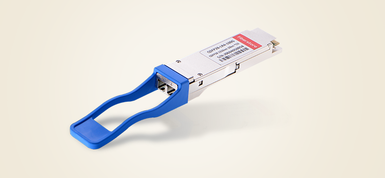
40G Connection of IBM G8264 Switch

For 40G connection, both fiber optic connection and copper connection can be built by using different components. A 40GBASE QSFP+ to QSFP+ DAC can provide connection between IBM G8264 and target devices up to 7 meters. With multimode fiber optic cables, distance up to 100 meters (OM3) and 150 meters (OM4) can be reached, when using with 40GBASE-SR4 QSFP+ transceivers. For long distance 40G transmission, 40GBSE-LR QSFP+ transceiver and single-mode fiber optic cable with LC connectors are suggested. Related components for IBM G8264 switch are concluded in the following chart.

Modules Cable & Connector Distance
49Y7884: QSFP+ 40GBASE-SR Transceiver MTP connector, MMF 100 m(OM3)
100 m(OM4)
00D6222: 40GBASE-LR4 QSFP+ Transceiver LC connector, SMF 10 km
BN-QS-QS-CBL-1M: QSFP-to-QSFP cable (1 meter) 1-7 m
BN-QS-QS-CBL-3M: QSFP-to-QSFP cable (3 meter)
Conclusion

To make full used of the switches in data center with great flexibility, both the selection of switch and cabling solutions is very important. IBM G8264 as a switch with great flexibility is an ideal solution for data center upgrading to 40G. The above mentioned modules and cables are all provided by FS.COM, which are IBM G8264 compatible and are fully tested on the IBM G8264 switches. Kindly contact sales@fs.com for more details, if you are interested.

Cisco ME 3400 Series Switches Cabling Solution

Cisco is the leading provider of switches in telecommunication industry. Its switches cover a wide range of applications. One of them is deigned for Metro Ethernet application, which is widely used and known as Cisco ME 3400 series. It is a series of switches which support data rate ranging from 10 M (Mbps) to 1000 M (1 Gbps) with advantages of safety, flexibility, simple deployment and trouble shooting in network. There are several Cisco ME 3400 switch modules with different configurations to satisfy different market needs. The following table is the detailed port information of these switches.

Switch Model Port Information
Cisco ME 3400-24TS-AC 24 10/100 FastEthernet ports and 2 SFP module ports, AC power
Cisco ME 3400-24TS-DC 24 10/100 FastEthernet ports and 2 SFP module ports, DC power
Cisco ME-3400-24FS-A 24 100BASE-FX SFP module ports and 2 Gigabit Ethernet SFP module ports, AC power
Cisco ME 3400G-12CS-AC 12 dual-purpose ports and 4 SFP module ports, AC power
Cisco ME 3400G-12CS-DC 12 dual-purpose ports and 4 SFP module ports, DC power
Cisco ME 3400G-2CS 2 dual-purpose ports and 2 SFP module ports, AC power
Ports On Cisco ME 3400 Switches

Although Cisco ME 3400 has a variety of port configurations, there are mainly three types of ports on the panel rear of Cisco ME 3400 switches concluded from the above table. They are RJ45 port, SFP port and dual-purpose port. The following part will illustrate how to use these ports to connect Cisco ME 3400 switches in network.

RJ45 Port Connection
RJ45 Ports on Cisco ME 3400 Switches

It is widely known that RJ45 port are based on copper. The RJ45 Ethernet ports on Cisco 3400 switches can be connected with 10Base-T, 100Base-TX, or 1000Base-T devices via copper cables that are attached with RJ45 connector (shown in the above picture). One of the benefits of using these ports is that they can configure themselves to operate at the speed of attached devices from 10 M, 100 M to 1000 M. If the attached ports do not support auto-negotiation, the specific speed and duplex parameters can be set to the required value.

Cisco ME 3400 SFP port connection
SFP Ports on Cisco 3400 Switches

The SFP ports on Cisco ME 3400 switches are base on either fiber optic or copper. For a fiber optic connection, a fiber optic SFP module should be plugged in the SFP port firstly, then one end of fiber optic cable with fiber optic connector (usually LC connector) should be inserted into the interface of the SFP module (shown in the above picture). Then insert the other cable end into a fiber optic connector on the target device. When the status LED of the port turns green a fiber optic link is established. If the connection is based copper cable, copper SFP module and copper cable attached with RJ45 connectors should be used to link the switch and target device. Two Cisco ME 3400 switches could be connected with SFP module patch cable (as shown in the following picture).

two Cisco ME 3400 Switch connected by SFP patch cable
Dual-Purpose Ports on Cisco ME 3400 Switches

A big highlight of Cisco ME 3400 switches is its dual-purpose port. Please note that only Cisco ME 3400G-12CS-DC/AC and Cisco ME 3400G-2CS have such kind of ports. Literally, dual-purpose can be used in two different ways. One is for fiber optic connection and one is for copper connection. These ports can be can be configured as either 10/100/1000M ports or as SFP module ports according to the needs. The switch dynamically selects the media type for each dual port (10/100/1000BASE-T or SFP). When a link is achieved on one media type, the switch disables the other media type until the active link goes down. If links are active on both media, the SFP module port has priority. The following picture shows part of the Cisco ME 3400G-12CS dual-purpose ports. The Cisco ME3400G-2CS switch dual-purpose ports are similar to those shown in this section.

Cisco ME 3400 dual-purpose port information

The following picture shows both fiber optic cable and copper cables connection with Cisco ME 3400G-12CS via dual-purpose ports. For the RJ45 ports, RJ45 connector and copper cable are used. For the SFP ports, both fiber optic connection and copper connection can be achieved by using fiber optic SFP module and copper SFP module separately. Thus, Cisco ME 3400 switches armed with dual-purpose ports can greatly increase it flexibility during cabling and network designing.

dual-purpose port connection details

Cisco ME 3400 Series Switches Cabling Guide

As Cisco ME 3400 series switches could be connected to a variety types of network and devices, customer might be confused during the selecting of cables, connector and modules. The following table offers the detailed information how to connect Cisco ME 3400 switches to the network.

Port Type
Data Rate
Connectors/Modules & Cables
RJ45 Ports 10BASE-T ports  RJ-45 connectors, two-pair Cat 3, 4, or 5 unshielded twisted-pair (UTP)
100BASE-TX ports  RJ-45 connectors, two-pair Cat 5 UTP
SFP Ports 100M GLC-GE-100FX LC duplex, MMF
GLC-FE-100FX
GLC-FE-100EX LC duplex, SMF
GLC-FE-100ZX
GLC-FE-100LX
GLC-FE-100BX-D LC simplex, SMF
GLC-FE-100BX-U
1000M (1G) GLC-SX-MM LC duplex, MMF
GLC-SX-MMD
SFP-GE-S
GLC-EX-SMD LC duplex, SMF
GLC-LH-SM
GLC-ZX-SM
GLC-ZX-SMD
GLC-LH-SMD
SFP-GE-Z
SFP-GE-L
CWDM SFP
DWDM SFP
GLC-BX-U LC simplex, SMF
GLC-BX-D
RJ-45, Cat 5
GLC-T
SFP-GE-T

All the above mentioned products can be provided in Fiberstore (FS.COM). If you are interested please contact sales@fs.com or visit FS.COM for more details.

Related Articles: Deploying 48-Port Gigabit PoE Managed Switch in Different Networks

                              How to Deploy 48 Port 10GE Switch in Data Center?